1998 NISSAN QUEST length
[x] Cancel search: lengthPage 45 of 260
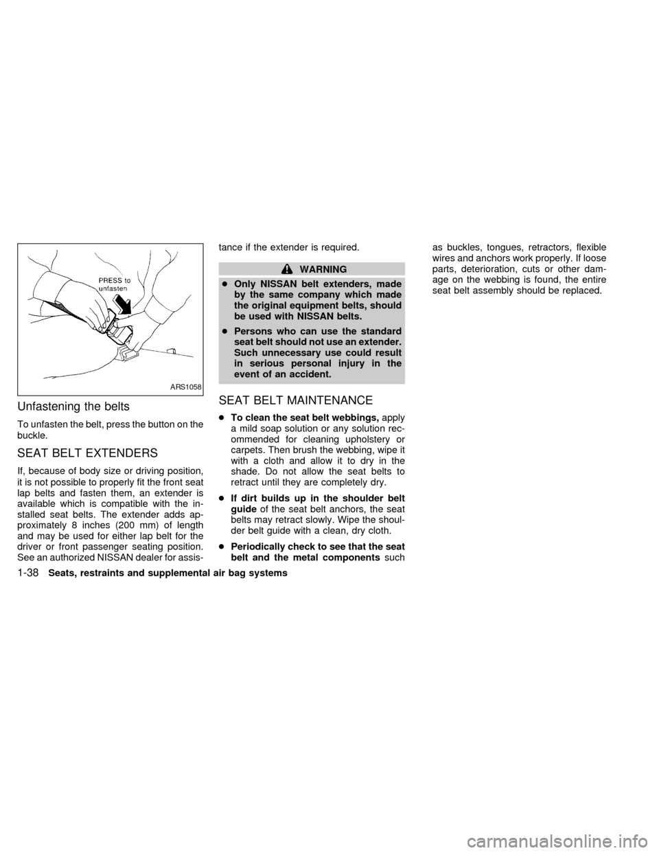
Unfastening the belts
To unfasten the belt, press the button on the
buckle.
SEAT BELT EXTENDERS
If, because of body size or driving position,
it is not possible to properly fit the front seat
lap belts and fasten them, an extender is
available which is compatible with the in-
stalled seat belts. The extender adds ap-
proximately 8 inches (200 mm) of length
and may be used for either lap belt for the
driver or front passenger seating position.
See an authorized NISSAN dealer for assis-tance if the extender is required.
WARNING
cOnly NISSAN belt extenders, made
by the same company which made
the original equipment belts, should
be used with NISSAN belts.
cPersons who can use the standard
seat belt should not use an extender.
Such unnecessary use could result
in serious personal injury in the
event of an accident.
SEAT BELT MAINTENANCE
cTo clean the seat belt webbings,apply
a mild soap solution or any solution rec-
ommended for cleaning upholstery or
carpets. Then brush the webbing, wipe it
with a cloth and allow it to dry in the
shade. Do not allow the seat belts to
retract until they are completely dry.
cIf dirt builds up in the shoulder belt
guideof the seat belt anchors, the seat
belts may retract slowly. Wipe the shoul-
der belt guide with a clean, dry cloth.
cPeriodically check to see that the seat
belt and the metal componentssuchas buckles, tongues, retractors, flexible
wires and anchors work properly. If loose
parts, deterioration, cuts or other dam-
age on the webbing is found, the entire
seat belt assembly should be replaced.
ARS1058
1-38Seats, restraints and supplemental air bag systems
ZX
Page 59 of 260
4. Pull on the third row shoulder belt until all
of the belt is fully extended . At this time,
the belt retractor is in the automatic lock-
ing mode (child restraint mode). The
lap/shoulder belt reverts back to emer-
gency locking mode when it is discon-
nected from the tether strap and fully
retracted.
5. Allow the belt to retract. Tighten the
tether strap to remove any slack.
6. Before placing the child in the child re-
straint, use force to tilt the child restraint
from side to side, and tug it forward to
make sure it is securely held in place.
7.
Check that the retractor is in the automatic
locking mode by trying to pull more belt
out of the retractor. If you cannot pull any
more belt webbing out of the retractor, the
belt is in the automatic locking mode.
8. Check to make sure the child restraint is
properly secured prior to each use. If the
belt is not locking, repeat steps 4 through
7.
INSTALLATION ON THREE-
PASSENGER BENCH SEAT IN
THIRD ROW
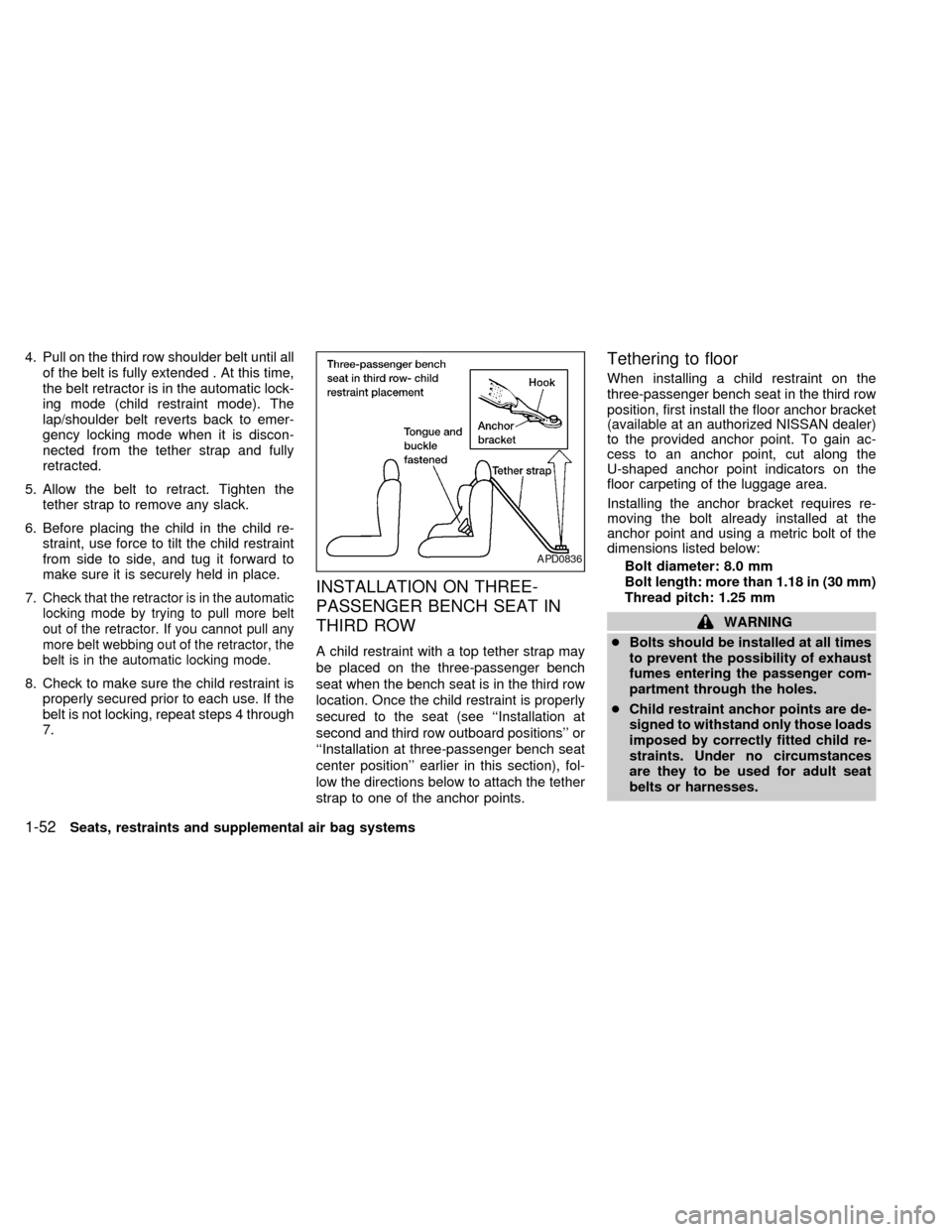
A child restraint with a top tether strap may
be placed on the three-passenger bench
seat when the bench seat is in the third row
location. Once the child restraint is properly
secured to the seat (see ``Installation at
second and third row outboard positions'' or
``Installation at three-passenger bench seat
center position'' earlier in this section), fol-
low the directions below to attach the tether
strap to one of the anchor points.
Tethering to floor
When installing a child restraint on the
three-passenger bench seat in the third row
position, first install the floor anchor bracket
(available at an authorized NISSAN dealer)
to the provided anchor point. To gain ac-
cess to an anchor point, cut along the
U-shaped anchor point indicators on the
floor carpeting of the luggage area.
Installing the anchor bracket requires re-
moving the bolt already installed at the
anchor point and using a metric bolt of the
dimensions listed below:
Bolt diameter: 8.0 mm
Bolt length: more than 1.18 in (30 mm)
Thread pitch: 1.25 mm
WARNING
cBolts should be installed at all times
to prevent the possibility of exhaust
fumes entering the passenger com-
partment through the holes.
cChild restraint anchor points are de-
signed to withstand only those loads
imposed by correctly fitted child re-
straints. Under no circumstances
are they to be used for adult seat
belts or harnesses.
APD0836
1-52Seats, restraints and supplemental air bag systems
ZX
Page 95 of 260

The autolamp system allows the headlights
to be set so they turn on and off automati-
cally. The autolamp system can turn on the
headlights automatically when it is dark,
turn off the headlights when it is light, and
keep the headlights on for up to three
minutes after you turn the key to OFF.
To set the autolamp system:
1. Make sure the headlight switch is in the
OFF position. If the headlight switch is in
the
orposition, the autolamp
system is canceled.
2. Turn the ignition key to ON.3. Use the autolamp switch to activate the
autolamp feature. It is to the left of the
steering wheel.
4. Turn the switch to the right. A slight
detent in the switch indicates it has been
turned past the off position. After the
switch is turned past the detent, the
autolamp automatically turns the lamps
on and off.
Shut-off delay
The length of time the autolamps stay on
after the ignition is turned to OFF depends
on how far the switch is turned to the right.
If the switch is turned all the way to the right,
the headlights stay on about three minutes
after the ignition is turned to OFF. If the
switch is turned only a little way to the right,
the headlights may stay on for less than a
minute.
To turn the autolamp system off, turn the
switch all the way to the left until the detent
is felt.Be sure you do not put anything on top
of the photo sensor located in the top
right side of the instrument panel. The
photo sensor controls the autolamp; if it
is covered, the photo sensor reacts as if
it is dark out and the headlights will
illuminate.
AIC0041AIC0584
AUTOLAMP SWITCH
(if so equipped)
2-14Instruments and controls
ZX
Page 145 of 260
creases or decreases the level of treble, as
indicated by the number of bar segments
showing in the display window.
Following treble adjustment, the display
window shows the current setting for three
seconds, then returns to the display prior to
adjustment.
BAL
Balance control allows you to adjust the
sound distribution between the right and left
speakers.
Push the BAL button either
or; BAL and the setting indicator bar
appear in the display window. Press the
BAL button
to shift the sound to the
right speakers. The single indicator bar
moves to the right of the display window.
Press the BAL button
to shift the
sound to the left speakers. The single indi-
cator bar moves to the left of the display
window. When the indicator bar is in the
center position the sound is equally distrib-
uted between the right and left speakers.
Following balance adjustment, the display
window shows the current setting for three
seconds, then returns to the display prior to
adjustment.
FADE
Fader control allows you to adjust sound
distribution between the front and rear
speakers.
Push the FADE button either
or; FADE and the setting indicator bar
appear in the display window. Press the
FADE button
to shift the sound to the
front speakers. The single indicator bar
moves to the right of the display window.
Press the FADE button
to shift the
sound to the rear speakers. The single
indicator bar moves to the left of the display
window. When the indicator bar is in the
center position the sound is equally distrib-
uted between the front and rear speakers.
Following fader adjustment, the display win-
dow shows the current setting for three
seconds, then returns to the display prior to
adjustment.
CASSETTE TAPE OPERATIONS
Turn the ignition key to ACC or ON, then
insert the cassette tape into the tape door
by lightly pushing it. Because of the power
loading feature, the cassette tape is auto-
matically pulled into the player and begins
to play.
CAUTION
Do not force the cassette tape into the
tape door. This could damage the
player.
When a cassette is inserted into the audio
system, the word TAPE and a cassette side
symbol (either one or two) illuminate in the
display window.
A cassette tape can be loaded with the
ignition ON whether or not the radio power
is on. Inserting a cassette tape with the
radio power off causes the audio system to
turn on. After the cassette is ejected, the
audio system turns off. Also, the power
antenna (if so equipped) stays in the down
position during cassette tape operation.
The cassette tape automatically changes
directions to play the other side when the
first side is completed.
cTo maintain good quality sound,
NISSAN recommends using cassette
tapes of 60 minutes or shorter in
length.
cCassette tapes should be removed
from the player when not in use. Store
4-18Heater, air conditioner and audio systems
ZX
Page 155 of 260
WARNING
Do not leave children, unreliable
adults, or pets alone in your vehicle.
They could accidently injure them-
selves or others through inadvertent
operation of the vehicle. Also, on hot,
sunny days, temperatures in a closed
vehicle could quickly become high
enough to cause severe or possibly
fatal injuries to people or animals.
EXHAUST GAS
(Carbon Monoxide)
WARNING
Do not breathe exhaust gases; they
contain colorless and odorless carbon
monoxide. Carbon monoxide is dan-
gerous. It can cause unconsciousness
or death.
cIf you suspect that exhaust fumes
are entering the vehicle, drive with
all windows fully open, and have the
vehicle inspected immediately.
cDo not run the engine in closed
spaces such as a garage for any
longer than is absolutely necessary.c
Do not park the vehicle with the en-
gine running for any extended length
of time.
cKeep the rear door and flip-up rear
window closed while driving, other-
wise exhaust gases could be drawn
into the passenger compartment. If
you must drive in this manner for
some reason, take the following
steps.
1. Open all the windows.
2. Set the air recirculate switch to off
and the fan control dial at four
(high) to circulate the air.
cIf electrical wiring or other cable
connections must pass to a trailer
through a seal on the body, follow
the manufacturer's recommendation
to prevent carbon monoxide entry
into the vehicle.
cThe exhaust system and body
should be inspected by a qualified
mechanic whenever:
a. The vehicle is raised for service.b. You suspect that exhaust fumes
are entering into the passenger
compartment.
c. You notice a change in the sound
of the exhaust system.
d.
You have had an accident involv-
ing damage to the exhaust system,
underbody, or rear of the vehicle.
THREE WAY CATALYST
The three way catalyst is an emission con-
trol device installed in the exhaust system.
Exhaust gases in the three way catalyst are
burned at high temperatures to help reduce
pollutants.
WARNING
cThe exhaust gas and the exhaust
system are very hot. Keep people or
flammable materials away from the
exhaust pipe.
cDo not stop or park the vehicle over
flammable materials such as dry
grass, waste paper or rags. They
may ignite and cause a fire.
PRECAUTIONS WHEN
STARTING AND DRIVING
5-2Starting and driving
ZX
Page 238 of 260

ModelVG30E
TypeGasoline, 4-cycle
Cylinder arrangement6-cylinder, V slanted at 60É
Bore ý Stroke in (mm) 3.425 ý 3.268 (87.0 ý 83.0)
Displacement cu in (cm
3) 180.62 (2,960)
Firing order1,2,3,4,5,6* (See illustration below)
Idle speed rpm
See the ``Important Vehicle Information'' label on the underside of the hood. Ignition timing degree (B.T.D.C.)
at idle speed degree/rpm
CO percentage at idle speed
[No air] %
Spark plug
StandardBKR5EY
ColdBKR6EY
Spark plug gap in (mm) 0.031 to 0.035 (0.8 to 0.9)
Camshaft operationTiming belt** (See note below)
Drive belts
[Width ý Length] in (mm)
Generator belt0.7008 ý 33.66 (17.80 ý 855)
Air conditioner compressor0.5606 ý 46.65 (14.24 ý 1,185)
Power steering pump0.5606 ý 40.74 (14.24 ý 1,035)
**NOTE: Periodic maintenance is necessary. Refer to the appropriate periodic
maintenance schedule in Chapter 8.
The spark ignition system of this vehicle meets all requirements of the
Canadian Interference-Causing Equipment Regulations.
ENGINE
Technical and consumer information10-7
ZX
Page 239 of 260

Road wheel Steel 5.5 - JJ ý 15
Aluminum 6.5 - JJ ý 15
Offset in (mm) 1.77 (45)
Tire size Conventional P205/75R15 97 S
Painted cast aluminum* P205/75R15 97 S
Machined cast aluminum P215/70R15 97 H
Spare T125/90D16
P205/75R15 97 S*
P215/70R15 97 T*
*: OptionOverall length in (mm) 189.9 (4,824)
Overall width in (mm) 73.7 (1,871)
Overall height in (mm) 67.6 (1,717)
Front tread in (mm) 63.4 (1,610)
Rear tread in (mm) 63.4 (1,610)
Wheelbase in (mm) 112.2 (2,850)
Gross vehicle weight
rating lb (kg)
See the ``F.M.V.S.S. certification label''
on the left center pillar. Gross axle weight rating
Front lb (kg)
Rear lb (kg)
WHEEL/TIRE SIZE DIMENSIONS AND WEIGHTS
10-8Technical and consumer information
ZX
Page 249 of 260
affect vehicle/trailer handling, possibly
causing vehicle sway. When being
passed by larger vehicles, be prepared
for possible changes in crosswinds that
could affect vehicle handling. If swaying
does occur, firmly grip the steering
wheel, steer straight ahead, and immedi-
ately (but gradually) reduce vehicle
speed. This combination helps to stabi-
lize the vehicle. Never increase speed.
cBe careful when passing other vehicles.
Passing while towing a trailer requires
considerably more distance than normal
passing. Remember the length of the
trailer must also pass the other vehicle
before you can safely change lanes.
cTo maintain engine braking efficiency
and electrical charging performance, do
not use overdrive.
cAvoid holding the brake pedal down too
long or too frequently. This could cause
the brakes to overheat, resulting in re-
duced braking efficiency.
When towing a trailer, change fluid in the
transmission more frequently. For addi-
tional information see the ``Mainte-
nance'' section earlier in this manual.Department of Transportation (DOT) Qual-
ity Grades: All passenger car tires must
conform to Federal Safety Requirements in
addition to these grades.
Treadwear
Treadwear grade is a comparative rating
based on tire wear rate when tested under
controlled conditions on specified govern-
ment test courses. For example, a tire
graded 150 would wear one and a half
(1-1/2) times as well on the government
course as a tire graded 100. However,
relative tire performance depends on actual
driving conditions, and may vary signifi-
cantly, due to variations in driving habits,
service practices and differences in road
characteristics and climate.
Traction AA, A, B and C
The traction grades, from highest to lowest,
are AA, A, B, and C. Those grades repre-
sent the tire's ability to stop on wet pave-
ment as measured under controlled condi-
tions, on specified government test surfaces
of asphalt and concrete. A tire marked C
may have poor traction performance.
WARNING
The traction grade assigned to your
vehicle tire's is based on straight-
ahead braking traction tests, and does
not include acceleration, cornering, hy-
droplaning, or peak traction character-
istics.
Temperature A, B and C
Temperature grades are A (the highest), B,
and C. They represent a tire's resistance to
heat build-up, and its ability to dissipate
heat when tested under controlled condi-
tions on a specified indoor laboratory test
wheel. Sustained high temperature can
cause tire material to degenerate, reducing
tire life. Excessive temperatures can lead to
sudden tire failure. Grade C corresponds to
a performance level which all passenger car
tires must meet under the Federal Motor
Vehicle Safety Standard No. 109. Grades A
and B represent higher levels of perfor-
mance on laboratory test wheels than the
minimum required by law.
UNIFORM TIRE QUALITY
GRADING
10-18Technical and consumer information
ZX