Page 9 of 24
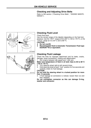
Removal and Installation
V1Air bag module
V2Steering wheel
V3Spiral cable
V4Combination switch
V5Steering column assembly
V6Column cover
V7Lower shaft
V8Coupling
CAUTION:
+The rotation of the spiral cable (SRS ``Air bag'' component
part) is limited. If the steering gear must be removed, set
the front wheels in the straight-ahead direction. Do not
rotate the steering column while the steering gear is
removed.
+Remove the steering wheel before removing the steering
lower joint to avoid damaging the SRS spiral cable.
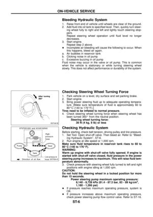
STEERING WHEEL
+Remove air bag module and spiral cable. Refer to RS section
(``Removal Ð Air Bag Module and Spiral Cable'', ``SUPPLE-
MENTAL RESTRAINT SYSTEM'').
SST758C
SBF812E
STEERING WHEEL AND STEERING COLUMN
ST-8
Page 10 of 24

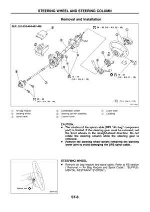
+Align spiral cable correctly when installing steering wheel.
a. Set the front wheels in the straight-ahead position.
b. Make sure that the spiral cable is in the neutral position.
The neutral position is detected by turning left 2.5 revolutions
from the right end position. Align the two marks (
,
m).
CAUTION:
The spiral cable may snap due to steering operation if the
cable is installed in an improper position.
Also, with the steering linkage disconnected, the cable may
snap by turning the steering wheel beyond the limited number
of turns. (The spiral cable can be turned up to 2.5 turns from
the neutral position to both the right and left.)
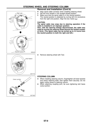
+Remove steering wheel with Tool.
STEERING COLUMN
+When installing steering column, ®ngertighten all lower bracket
and clamp retaining bolts; then tighten them securely. Do not
apply undue stress to steering column.
+When attaching coupling joint, be sure tightening bolt faces
cutout portion.
SRS276
SST777C
SST759C
STEERING WHEEL AND STEERING COLUMN
Removal and Installation (Cont'd)
ST-9
Page 11 of 24
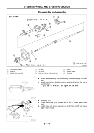
Disassembly and Assembly
V1Combination switch
V2Lock nut
V3Jacket tube assembly
V4Tilt lever
V5Tilt spring
V6Steering column shaft assembly
V7Band
V8Column cover
V9Coupling
+When disassembling and assembling, unlock steering lock with
key.
+Install lock nut on steering column shaft and tighten the nut to
speci®cation.
: 25-34Nzm (2.5 - 3.5 kg-m, 18 - 25 ft-lb)
+Steering lock
a. Break self-shear type screws with a drill or other appropriate
tool.
b. Install new self-shear type screws and then cut off self-shear
type screw heads.
SST760C
SST490C
SST742A
STEERING WHEEL AND STEERING COLUMN
ST-10
Page 12 of 24
Inspection
+When steering wheel does not turn smoothly, check the steer-
ing column as follows and replace damaged parts.
a. Check column bearings for damage and unevenness. Lubricate
with recommended multi-purpose grease or replace steering
column as an assembly, if necessary.
b. Check steering column lower shaft for deformation and break-
age. Replace if necessary.
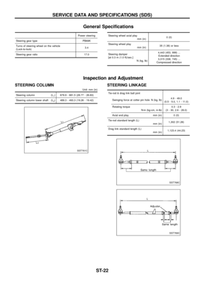
+When the vehicle comes into a light collision, check length ``L
1''
and ``L
2''.
Steering column length ``L
1'':
679.9 - 681.5 mm (26.77 - 26.83 in)
Steering column lower shaft length ``L
2'':
489.3 - 493.3 mm (19.26 - 19.42 in)
If out of the speci®cations, replace steering column shaft or
steering column as an assembly.
Tilt mechanism
After installing steering column, check tilt mechanism operation.
SST761C
SST582BD
STEERING WHEEL AND STEERING COLUMN
ST-11
Page 13 of 24
Description
CAUTION:
+Parts which can be disassembled are strictly limited. Never
disassemble parts other than those speci®ed.
+Disassemble in as clean a place as possible.
+Clean your hands before disassembly.
+Do not use rags; use nylon cloths or paper towels.
+Follow the procedures and cautions indicated in the Ser-
vice Manual.
SST762C
POWER STEERING SYSTEM (Model: PB69K)
ST-12
Page 14 of 24
Removal and Installation
Before removal, clean gear housing and oil pump exteriors
using a steam cleaner. Then dry with compressed air.
+Plug openings of gear housing, and securely locate hose con-
nectors at a position higher than oil pump and cover with paper
towels.
+Be extremely careful to prevent entry of foreign matter into
hoses through connectors.
+When installing pitman arm, align four grooves of pitman arm
serrations with four projections of sector shaft serrations, and
install and tighten lock washer and nut.
Inspection
Do not disassemble for power steering gear assembly.
TURNING TORQUE MEASUREMENT
1. Measure turning torque at 360É position.
a. Install steering gear on Tool.
SST774C
SST040-A
POWER STEERING GEAR (Model: PB69K)
ST-13
Page 15 of 24
b. Turn stub shaft all the way to right and left several times.
c. Measure turning torque at 360É position from straight-ahead
position with Tools.
Turning torque at 360É
0.15 - 0.78 Nzm (1.5 - 8.0 kg-cm, 1.3 - 6.9 in-lb)
2. Measure turning torque at straight-ahead position.
Straight-ahead position is a position where stub shaft is
turned 2.14 turns (two full turns and 50É) from lock position.
Turning torque at straight-ahead position:
0.2 - 0.5 Nzm (2 - 5 kg-cm, 1.7 - 4.3 in-lb)
higher than turning torque at 360É
Maximum turning torque:
0.44 - 1.18 Nzm (4.5 - 12 kg-cm, 3.9 - 10.4 in-lb)
3. Check sector shaft end play in neutral position.
End play:
Less than 0.1 mm (0.004 in)
If turning torque and end play are not within speci®cations,
replace power steering gear assembly.
SST652AA
POWER STEERING GEAR (Model: PB69K)
Inspection (Cont'd)
ST-14
Page 16 of 24
Removal and Installation
YST001
POWER STEERING OIL PUMP
ST-15