Page 2 of 24

Supplemental Restraint System (SRS) ``AIR
BAG'' and ``SEAT BELT PRE-TENSIONER''
The Supplemental Restraint System such as ``AIR BAG'' and ``SEAT BELT PRE-TENSIONER'' used along with
a seat belt, helps to reduce the risk or severity of injury to the driver and front passenger in a frontal collision.
The SRS system composition which is available to NISSAN MODEL Y61 is as follows (The composition var-
ies according to the destination.):
Driver air bag module (located in the center of the steering wheel), front passenger air bag module (located
on the instrument panel on passenger side), seat belt pre-tensioner, a diagnosis sensor unit, warning lamp,
wiring harness and spiral cable.
Information necessary to service the system safely is included in theRS sectionof this Service Manual.
WARNING:
+To avoid rendering the SRS inoperative, which could increase the risk of personal injury or death
in the event of a collision which would result in air bag in¯ation, all maintenance must be performed
by an authorized NISSAN dealer.
+Improper maintenance, including incorrect removal and installation of the SRS, can lead to per-
sonal injury caused by unintentional activation of the system. For removal of Spiral Cable and Air
Bag Module, see the RS section.
+Do not use electrical test equipment on any circuit related to the SRS unless instructed to in this
Service Manual. Spiral cable and wiring harnesses covered with yellow insulation either just before
the harness connectors or for the complete harness are related to the SRS.
Precautions for Steering System
+Before disassembly, thoroughly clean the outside of the unit.
+Disassembly should be done in a clean work area. It is important to prevent the internal parts from
becoming contaminated by dirt or other foreign matter.
+Place disassembled parts in order, on a parts rack, for easier and proper assembly.
+Use nylon cloths or paper towels to clean the parts; common shop rags can leave lint that might
interfere with their operation.
+Before inspection or reassembly, carefully clean all parts with a general purpose, non-¯ammable
solvent.
+Before assembly, apply a coat of recommended ATF* to hydraulic parts. Vaseline may be applied
to O-rings and seals. Do not use any grease.
+Replace all gaskets, seals and O-rings. Avoid damaging O-rings, seals and gaskets during instal-
lation. Perform functional tests whenever designated.
*: Automatic Transmission Fluid type DEXRON
TMIII or equivalent
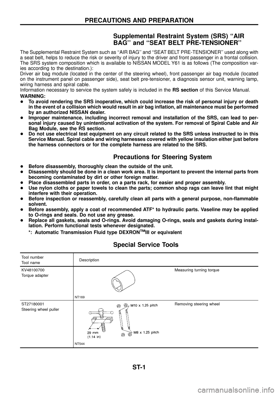
Special Service Tools
Tool number
Tool nameDescription
KV48100700
Torque adapter
NT169
Measuring turning torque
ST27180001
Steering wheel puller
NT544
Removing steering wheel
PRECAUTIONS AND PREPARATION
ST-1
Page 4 of 24

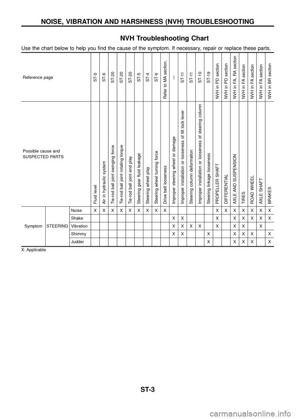
NVH Troubleshooting Chart
Use the chart below to help you ®nd the cause of the symptom. If necessary, repair or replace these parts.
Reference pageST-5
ST-6
ST-20
ST-20
ST-20
ST-5
ST-4
ST-6
Refer to MA section.
Ð
ST-11
ST-11
ST-10
ST-19
NVH in PD section
NVH in PD section
NVH in FA, RA section
NVH in FA section
NVH in FA section
NVH in FA section
NVH in BR section
Possible cause and
SUSPECTED PARTS
Fluid level
Air in hydraulic system
Tie-rod ball joint swinging force
Tie-rod ball joint rotating torque
Tie-rod ball joint end play
Steering gear ¯uid leakage
Steering wheel play
Steering wheel turning force
Drive belt looseness
Improper steering wheel or damage
Improper installation or looseness of tilt lock lever
Steering column deformation
Improper installation or looseness of steering column
Steering linkage looseness
PROPELLER SHAFT
DIFFERENTIAL
AXLE AND SUSPENSION
TIRES
ROAD WHEEL
AXLE SHAFT
BRAKES
Symptom STEERINGNoiseXXXXXXXXX XXXXXXX
Shake X X XXXXXX
VibrationXXXXXXXX
Shimmy X X X X X X X
Judder X X X X X
X: Applicable
NOISE, VIBRATION AND HARSHNESS (NVH) TROUBLESHOOTING
ST-3
Page 23 of 24
General Speci®cations
Power steering
Steering gear type PB69K
Turns of steering wheel on the vehicle
(Lock-to-lock)3.4
Steering gear ratio 17.0Steering wheel axial play
mm (in)0 (0)
Steering wheel play
mm (in)35 (1.38) or less
Steering damper
[at 0.3 m (1.0 ft)/sec.]
N (kg, lb)4,443 (453, 999) ...
Extended direction
3,315 (338, 745) ...
Compressed direction
Inspection and Adjustment
STEERING COLUMN
Unit: mm (in)
Steering column (L1) 679.9 - 681.5 (26.77 - 26.83)
Steering column lower shaft (L
2) 489.3 - 493.3 (19.26 - 19.42)
STEERING LINKAGE
Tie-rod & drag link ball joint
Swinging force at cotter pin hole N (kg, lb)4.9 - 49.0
(0.5 - 5.0, 1.1 - 11.0)
Rotating torque
Nzm (kg-cm, in-lb)0.3 - 2.9
(3 - 30, 2.6 - 26.0)
Axial end play mm (in) 0 (0)
Tie-rod standard length (L)
mm (in)1,302 (51.26)
Drag link standard length (L)
mm (in)1,123.4 (44.23)
SST761C
SST768C
SST769C
SERVICE DATA AND SPECIFICATIONS (SDS)
ST-22
Page 24 of 24
POWER STEERING SYSTEM
(Model: PB69K)
Steering wheel turning force
(at 360É from neutral posi-
tion and circumference of
steering wheel) N (kg, lb)39 (4, 9) or less
Oil pump pressure
kPa (bar, kg/cm
2, psi)8,140 - 8,728
(81.4 - 87.3, 83 - 89, 1,180 - 1,266)
at idling
Fluid capacity
m!(Imp ¯ oz)Approximately 1,000 (35.2)
Normal operating tempera-
ture ÉC (ÉF)60 - 80 (140 - 176)
Steering gear turning torque
Nzm (kg-cm, in-lb)
360É position from
straight-ahead position0.15 - 0.78 (1.5 - 8.0, 1.3 - 6.9)
Straight-ahead position
(As compared with steer-
ing wheel turned 360É)0.2 - 0.5 (2 - 5, 1.7 - 4.3) higher
Maximum turning torque 0.44 - 1.18 (4.5 - 12, 3.9 - 10.4)
Backlash at pitman arm top
end (in a straight-
ahead position) mm (in)0 - 0.1 (0 - 0.004)
End play (at sector shaft
end in neutral position)
mm (in)0.1 (0.004) or less
SERVICE DATA AND SPECIFICATIONS (SDS)
Inspection and Adjustment (Cont'd)
ST-23