Page 25 of 35
d. Tighten adapter plate to transmission case using 2 bolts.
e. Place dial indicator on rear end of counter gear.
f. Move counter gear up and down and measure dial indicator
de¯ection.
g. Select proper thrust washer using table below as a guide.
Counter gear end play:
0.10 - 0.25 mm (0.0039 - 0.0098 in)
Table for selecting proper counter gear front bearing
thrust washer:
Refer to SDS, MT-34.
6. Select proper reverse idler rear thrust washer when replacing
OD gear case, reverse idler gear, reverse idler shaft or reverse
idler front thrust washer.
a. Install reverse idler front gear, reverse idler needle bearings,
reverse idler front thrust washers and reverse idler shaft into
OD gear case.
+When replacing reverse idler rear thrust washer, install
either A or B.
Reverse idler rear thrust washer:
Refer to SDS, MT-34.
SMT578A
SMT442B
ASSEMBLY
Gear Components (Cont'd)
MT-24
Page 26 of 35
b. Place dial indicator on front end of reverse idler shaft.
c. Put straightedge on front surface of OD gear case as a stop-
per of reverse idler shaft.
d. Move reverse idler shaft up and down and measure reverse
idler gear end play.
Reverse idler gear end play:
0.30 - 0.53 mm (0.0118 - 0.0209 in)
e. If not within speci®cation, replace reverse idler rear thrust
washer with the other (A or B) and check again.
7. Install mainshaft and counter gear on adapter plate and main
drive gear on mainshaft.
a. Mount adapter plate on vise and apply multi-purpose grease to
counter gear rear bearing.
b. Install mainshaft a little on mainshaft front bearing.
+To allow for installation of counter gear, do not install
mainshaft completely.
c. Install counter gear on counter gear rear bearing and install
main drive gear, pilot bearing and spacer on mainshaft.
SMT433A
SMT438A
SMT440A
SMT441A
ASSEMBLY
Gear Components (Cont'd)
MT-25
Page 27 of 35
+When installing counter gear into counter gear rear
bearing, push up on upper roller of counter gear rear bear-
ing with screwdriver.
d. Install mainshaft and counter gear completely by tapping rear
side of adapter plate and pulling mainshaft.
8. Install rear side components on mainshaft and counter gear.
a. Install OD gear bushing while pushing on the front of counter
gear.
b. Install OD main gear.
+Pay attention to direction of OD main gear. (B is wider than
A as shown at left.)
c. Install adapter plate with gear assembly onto transmission
case.
d. Install OD gear needle bearing and then install OD counter gear
and reverse idler shaft.
e. Install reverse cone.
SMT442A
SMT443A
SMT444AA
SMT580AB
SMT582AA
ASSEMBLY
Gear Components (Cont'd)
MT-26
Page 28 of 35
f. Install insert springs and reverse baulk ring on OD coupling
sleeve. Then install them and OD baulk ring on OD counter
gear.
+Pay attention to direction of OD coupling sleeve.
g. Install reverse counter gear.
h. Install reverse gear needle bearing and then install reverse
main gear, reverse idler gear and reverse idler thrust washers.
i. Install reverse hub and mainshaft spacer.
+Pay attention to direction of reverse hub.
j. Install counter gear rear end bearing.
k. Separate adapter plate from transmission case and mount
adapter plate on vice again.
SMT571AA
SMT583A
SMT584AA
SMT585AA
SMT828C
ASSEMBLY
Gear Components (Cont'd)
MT-27
Page 29 of 35
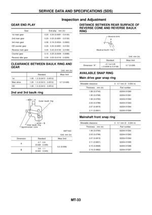
l. Select proper mainshaft C-ring to minimize clearance of
groove.
Allowable clearance of groove:
0 - 0.1 mm (0 - 0.004 in)
Mainshaft C-ring:
Refer to SDS, MT-34.
m. Install selected C-ring, C-ring holder and mainshaft rear snap
ring.
n. Select proper counter gear rear snap ring to minimize clear-
ance of groove.
Allowable clearance of groove:
0 - 0.1 mm (0 - 0.004 in)
Counter gear rear snap ring:
Refer to SDS, MT-34.
o. Install selected counter gear rear snap ring.
p. Install reverse coupling sleeve.
+Pay attention to its direction.
q. Measure each gear end play as a ®nal check. Refer to
``DISASSEMBLY'', MT-15.
SMT829C
SMT830C
SMT831C
SMT832C
SMT833C
ASSEMBLY
Gear Components (Cont'd)
MT-28
Page 30 of 35
Shift Control Components
1. Install OD fork rod and OD shift fork. Then install retaining pin
into OD shift fork.
2. Install 1st & 2nd, 3rd & 4th and reverse shift fork onto coupling
sleeve.
3. Install striking rod into hole of shift forks, striking lever and
interlock and then install retaining pin into striking lever.
+Make sure that striking rod moves smoothly.
Case Components
1. Install front cover oil seal.
+Apply multi-purpose grease to seal lip.
2. Install selected counter gear front bearing shim onto transmis-
sion case.
+Apply multi-purpose grease.
3. Apply sealant to mating surface of transmission case.
4. Install gear assembly onto transmission case.
5. Install check spring and check ball into interlock stopper.
+Apply multi-purpose grease to check ball.
6. Install interlock stopper assembly and then tighten check ball
plug.
+Apply sealant to thread of check ball plug.
SMT834C
SMT374AA
SMT393AA
SMT835C
SMT460A
ASSEMBLY
MT-29
Page 31 of 35
7. Install stopper ring and main drive bearing snap ring.
8. Install front cover and gasket.
+Apply sealant to thread of 3 bolts shown left.
9. Apply sealant to mating surface of adapter plate.
10. Install OD gear case together with striking arm.
11. Install retaining pin into striking arm.
12. Install return spring and check ball and then install control hous-
ing.
+Apply sealant to mating surface of OD gear case.
SMT371A
SMT459A
SMT444B
SMT439B
SMT445B
ASSEMBLY
Case Components (Cont'd)
MT-30
Page 32 of 35
13. Tighten control housing bolts.
Bolt head size:
A bolts 12 mm (0.47 in)
B bolts 13 mm (0.51 in)
SMT446BA
ASSEMBLY
Case Components (Cont'd)
MT-31


Mainshaft C-ring:
Refer to SDS, MT-34.
m. Install selected C-ring, C-ring ho")


B bolts 13 mm (0.51 in)
SMT446BA
ASSEMBLY
Case Components (Contd)
MT-31")