Page 17 of 35
d. Pull out counter gear rear end bearing.
e. Remove reverse idler gear and reverse idler thrust washers.
f. Pull out reverse main gear together with mainshaft spacer and
reverse synchronizer hub. Then remove reverse gear needle
bearings.
g. Pull out reverse counter gear.
h. Remove OD coupling sleeve together with OD baulk ring,
reverse baulk ring and spring inserts.
i. Pull out reverse gear bushing.
j. Pull out OD counter gear together with reverse cone.
SMT827C
SMT380A
SMT773A
SMT770A
SMT771A
DISASSEMBLY
Gear Components (Cont'd)
MT-16
Page 18 of 35
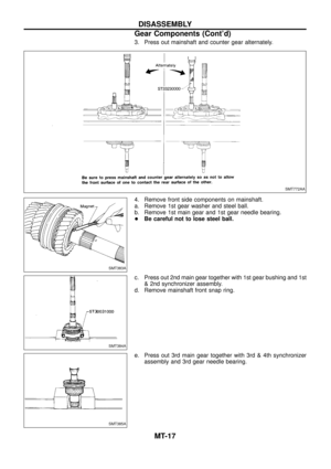
3. Press out mainshaft and counter gear alternately.
4. Remove front side components on mainshaft.
a. Remove 1st gear washer and steel ball.
b. Remove 1st main gear and 1st gear needle bearing.
+Be careful not to lose steel ball.
c. Press out 2nd main gear together with 1st gear bushing and 1st
& 2nd synchronizer assembly.
d. Remove mainshaft front snap ring.
e. Press out 3rd main gear together with 3rd & 4th synchronizer
assembly and 3rd gear needle bearing.
SMT772AA
SMT383A
SMT384A
SMT385A
DISASSEMBLY
Gear Components (Cont'd)
MT-17
Page 19 of 35
5. Remove front side components on counter gear.
a. Remove counter gear rear thrust bearing.
b. Remove sub gear components.
6. Remove main drive gear bearing.
a. Remove main drive gear snap ring.
b. Press out main drive gear bearing.
7. Remove bearings from case components.
SMT404AA
SMT470A
SMT420AA
SMT483CB
DISASSEMBLY
Gear Components (Cont'd)
MT-18
Page 20 of 35
Shift Control Components
+Check contact surface and sliding surface for wear, scratches,
projections or other damage.
Gear Components
GEARS AND SHAFTS
+Check shafts for cracks, wear or bending.
+Check gears for excessive wear, chips or cracks.
SYNCHRONIZERS
+Check spline portion of coupling sleeves, hubs, and gears for
wear or cracks.
+Check baulk rings for cracks or deformation.
+Check shifting inserts for wear or deformation.
+Check insert springs for deformation.
+Measure wear of main drive, 1st and OD baulk rings.
Clearance between baulk ring and gear:
Refer to SDS, MT-33.
+If the clearance is smaller than the wear limit, replace baulk
ring.
SMT398A
SMT386A
SMT423A
SMT427C
SMT140
INSPECTION
MT-19
Page 21 of 35
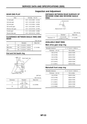
+Measure wear of 2nd and 3rd baulk rings.
a. Place baulk rings in position on synchronizer cone.
b. While holding baulk rings against synchronizer cone as far as
it will go, measure dimensions ``A'' and ``B''.
Standard:
A 0.7 - 0.9 mm (0.028 - 0.035 in)
B 0.6 - 1.1 mm (0.024 - 0.043 in)
Wear limit:
0.2 mm (0.008 in)
+If dimension ``A'' or ``B'' is smaller than the wear limit,
replace outer baulk ring, inner baulk ring and synchronizer
cone as a set.
+Measure wear of reverse baulk ring.
a. Place baulk ring in position on reverse cone.
b. While holding baulk ring against reverse cone as far as it will
go, measure dimension ``A'' with dial indicator.
Dimension ``A'':
Standard þ0.1 to 0.35 mm (þ0.0039 to 0.0138 in)
Wear limit 0.7 mm (0.028 in)
c. If dimension ``A'' is larger than the wear limit, replace baulk ring.
BEARINGS
+Make sure bearings roll freely and are free from noise, crack,
pitting or wear.
SMT041BC
SMT042B
SMT424A
SMT418A
INSPECTION
Gear Components (Cont'd)
MT-20
Page 22 of 35
Gear Components
1. Install bearings into case components.
2. Install main drive gear bearing.
a. Press main drive gear bearing.
b. Select proper main drive gear snap ring to minimize clearance
of groove.
Allowable clearance of groove:
0 - 0.1 mm (0 - 0.004 in)
Main drive gear snap ring:
Refer to SDS, MT-33.
c. Install selected snap ring on main drive gear.
3. Install components on counter gear.
a. Install sub-gear components.
+When installing sub-gear snap ring, tap sub-gear snap ring
into position on counter gear.
SMT484CB
SMT425AA
SMT426A
SMT577AA
ASSEMBLY
MT-21
Page 23 of 35
b. Install counter gear rear thrust bearing.
4. Install front side components on mainshaft.
a. Assemble 1st & 2nd synchronizer.
b. Assemble 3rd & 4th synchronizer.
c. Press on 3rd & 4th synchronizer assembly together with 3rd
main gear and 3rd gear needle bearing.
+Pay attention to direction of synchronizer assembly.
d. Select proper snap ring to minimize clearance of groove.
Allowable clearance of groove:
0 - 0.1 mm (0 - 0.004 in)
Mainshaft front snap ring:
Refer to SDS, MT-33.
e. Install selected snap ring on mainshaft.
SMT405A
SMT614B
SMT615B
SMT399A
SMT400A
ASSEMBLY
Gear Components (Cont'd)
MT-22
Page 24 of 35
f. Press on 1st & 2nd synchronizer assembly together with 2nd
main gear and 2nd gear needle bearing.
g. Press on 1st gear bushing using 1st gear washer.
h. Install 1st main gear and needle bearing.
i. Install steel ball and 1st gear washer.
+Apply multi-purpose grease to steel ball and 1st gear
washer before installing.
5. Select proper counter gear front bearing thrust washer when
replacing transmission case, counter gear, counter gear rear
thrust bearing or sub-gear components.
a. Install counter gear with sub-gear components, counter gear
front and rear bearing thrust washer on adapter plate.
b. Remove counter gear front bearing thrust washer from trans-
mission case.
c. Place adapter plate and counter gear assembly in transmission
case (case inverted).
SMT401A
SMT402A
SMT403A
SMT427AA
ASSEMBLY
Gear Components (Cont'd)
MT-23