Page 25 of 29
SFA889B
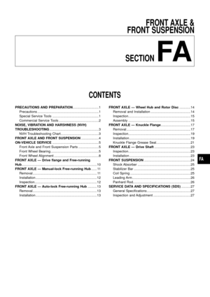
FRONT SUSPENSION
FA-24
Page 26 of 29

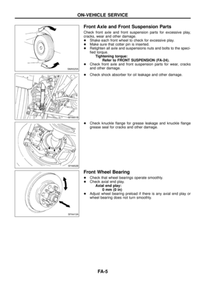
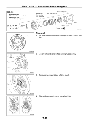
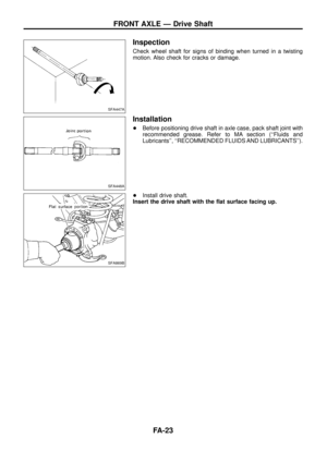
Shock Absorber
REMOVAL AND INSTALLATION
1. Support front axle case with jack.
2. Remove both upper and lower sides ®xing nuts.
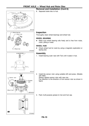
INSPECTION
Except for nonmetallic parts, clean all parts with suitable solvent
and dry with compressed air.
Use compressed air to blow dirt and dust off of nonmetallic parts.
+Check for oil leakage and cracks. Replace if necessary.
+Check piston rod for cracks, deformation and other damage.
Replace if necessary.
+Check rubber parts for wear, cracks, damage and deformation.
Replace if necessary.
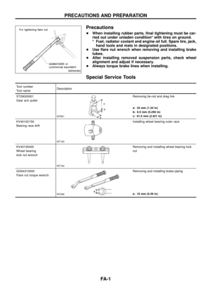
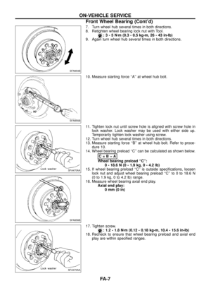
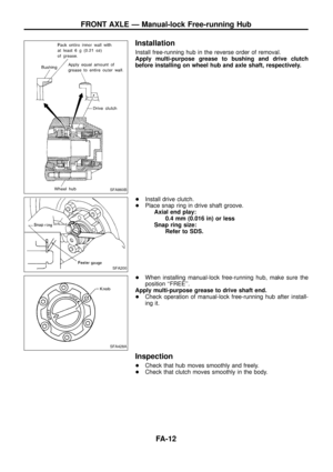
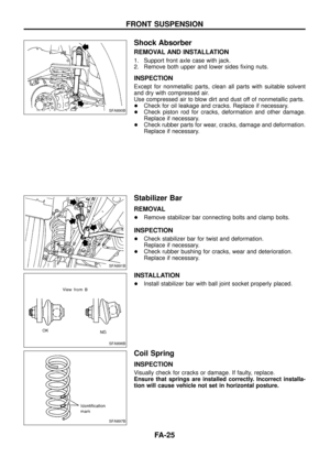
Stabilizer Bar
REMOVAL
+Remove stabilizer bar connecting bolts and clamp bolts.
INSPECTION
+Check stabilizer bar for twist and deformation.
Replace if necessary.
+Check rubber bushing for cracks, wear and deterioration.
Replace if necessary.
INSTALLATION
+Install stabilizer bar with ball joint socket properly placed.
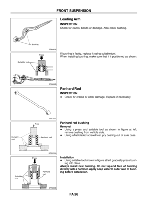
Coil Spring
INSPECTION
Visually check for cracks or damage. If faulty, replace.
Ensure that springs are installed correctly. Incorrect installa-
tion will cause vehicle not set in horizontal posture.
SFA890B
SFA891B
SFA896B
SFA897B
FRONT SUSPENSION
FA-25
Page 27 of 29
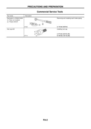
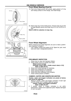
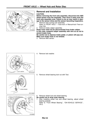
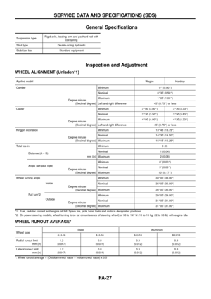
Leading Arm
INSPECTION
Check for cracks, bends or damage. Also check bushing.
If bushing is faulty, replace it using suitable tool.
When installing bushing, make sure that it is positioned as shown.
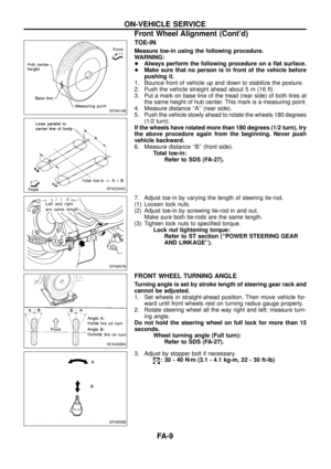
Panhard Rod
INSPECTION
+Check for cracks or other damage. Replace if necessary.
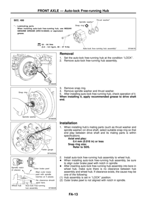
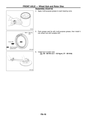
Panhard rod bushing
Removal
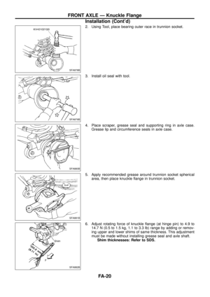
+Using a press and suitable tool as shown in ®gure at left,
remove bushing from vehicle side.
+Using a ¯at-bladed screwdriver, pry bushing out of axle case.
Installation
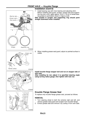
+Using suitable tool shown in ®gure at left, gradually press bush-
ing into place.
Always install new bushing. Do not tap end face of bushing
directly with a hammer. Apply soap water to outer wall of bush-
ing before installation.
SFA460A
SFA892B
SFA462A
SRA030A
SFA893B
FRONT SUSPENSION
FA-26
Page 28 of 29

General Speci®cations
Suspension typeRigid axle, leading arm and panhard rod with
coil spring
Strut type Double-acting hydraulic
Stabilizer bar Standard equipment
Inspection and Adjustment
WHEEL ALIGNMENT (Unladen*1)
Applied modelWagon Hardtop
Camber Minimum 0É (0.00É)
Degree minute
(Decimal degree)Nominal 0É30¢(0.50É)
Maximum 1É00¢(1.00É)
Left and right difference 45¢(0.75É) or less
Caster Minimum 3É00¢(3.00É) 3É20¢(3.33É)
Degree minute
(Decimal degree)Nominal 3É30¢(3.50É) 3É50¢(3.83É)
Maximum 4É00¢(4.00É) 4É20¢(4.33É)
Left and right difference 45¢(0.75É) or less
Kingpin inclination Minimum 13É45¢(13.75É)
Degree minute
(Decimal degree)Nominal 14É30¢(14.50É)
Maximum 15É15¢(15.25É)
Total toe-in Minimum 0 (0)
Distance (A þ B)
mm (in)Nominal 1 (0.04)
Maximum 2 (0.08)
Angle (left plus right)
Degree minute
(Decimal degree)Minimum 0¢(0.00É)
Nominal 5¢(0.08É)
Maximum 10¢(0.17É)
Wheel turning angle Minimum 33É00¢(33.00É)
Full turn*2Inside
Degree minute
(Decimal degree)Nominal 35É00¢(35.00É)
Maximum 35É00¢(35.00É)
Outside
Degree minute
(Decimal degree)Minimum 29É00¢(29.00É)
Nominal 31É00¢(31.00É)
Maximum 31É00¢(31.00É)
*1: Fuel, radiator coolant and engine oil full. Spare tire, jack, hand tools and mats in designated positions.
*2: On power steering models, wheel turning force (at circumference of steering wheel) of 98 to 147 N (10 to 15 kg, 22 to 33 lb) with engine idle.
WHEEL RUNOUT AVERAGE*
Wheel typeSteel Aluminum
6JJ-16 8JJ-16 6JJ-16 8JJ-16
Radial runout limit
mm (in)1.2
(0.047)0.8
(0.031)0.3
(0.012)0.3
(0.012)
Lateral runout limit
mm (in)1.2
(0.047)0.8
(0.031)0.3
(0.012)0.3
(0.012)
*: Wheel runout average = (Outside runout value + Inside runout value) x 0.5
SERVICE DATA AND SPECIFICATIONS (SDS)
FA-27
Page 29 of 29
0 (0)
Wheel bearing lock nuts
Tightening torque
Nzm (kg-m, ft-lb)167 - 196 (17 - 20, 123 - 145)
Retightening torque after
untightened
Nzm (kg-m, in-lb")
WHEEL BEARING
Wheel bearing axial end play
mm (in)0 (0)
Wheel bearing lock nuts
Tightening torque
Nzm (kg-m, ft-lb)167 - 196 (17 - 20, 123 - 145)
Retightening torque after
untightened
Nzm (kg-m, in-lb)3 - 5 (0.3 - 0.5, 26 - 43)
Measured starting force
At wheel hub bolt
N (kg, lb)A
Turning adjusting nut in tightening
direction and measuring starting
force
At wheel hub bolt
N (kg, lb)B
Calculated wheel bearing preload;
BþA
At wheel hub bolt
N (kg, lb)0 - 18.6 (0 - 1.9, 0 - 4.2)
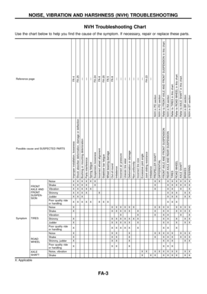
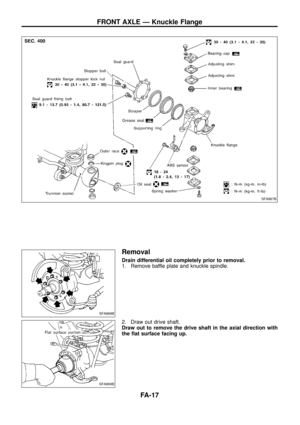
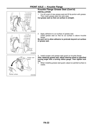
KNUCKLE FLANGE BEARING
Flange turning torque
Without trunnion seal
and drive shaft
Nzm (kg-m, ft-lb)1 - 3 (0.1 - 0.3, 0.7 - 2.2)
At knuckle arm ``F''
N (kg, lb)4.9 - 14.7 (0.5 - 1.5, 1.1 - 3.3)
Adjusting shims mm (in)Thickness Part number
0.075 (0.0030)
0.127 (0.0050)
0.254 (0.0100)
0.500 (0.0197)
0.762 (0.0300)40606-44000
40605-44000
40604-44000
40571-01J00
40603-44000
SFA882B
DRIVE SHAFT
Bir®eld joint axial end play
mm (in)0 (0)
Grease
Type Multi-purpose grease
Capacity g (oz) 50 - 60 (1.76 - 2.12)
Drive shaft axial end play
mm (in)0.4 (0.016) or less
Adjusting snap rings
mm (in)Thickness Part number
1.1 (0.043)
1.3 (0.051)
1.5 (0.059)
1.7 (0.067)
1.9 (0.075)
2.1 (0.083)39253-01J00
39253-01J01
39253-01J02
39253-01J03
39253-01J04
39253-01J05
SERVICE DATA AND SPECIFICATIONS (SDS)
Inspection and Adjustment (Cont'd)
FA-28