Page 9 of 29

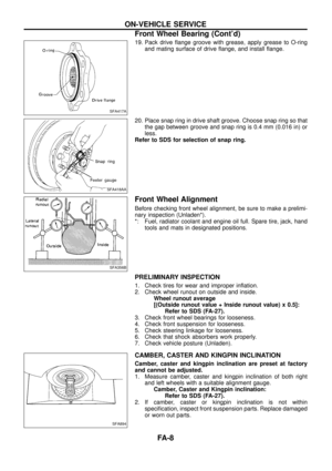
19. Pack drive ¯ange groove with grease, apply grease to O-ring
and mating surface of drive ¯ange, and install ¯ange.
20. Place snap ring in drive shaft groove. Choose snap ring so that
the gap between groove and snap ring is 0.4 mm (0.016 in) or
less.
Refer to SDS for selection of snap ring.
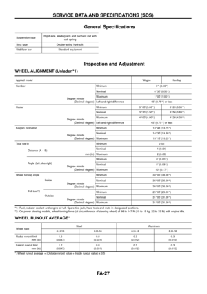
Front Wheel Alignment
Before checking front wheel alignment, be sure to make a prelimi-
nary inspection (Unladen*).
*: Fuel, radiator coolant and engine oil full. Spare tire, jack, hand
tools and mats in designated positions.
PRELIMINARY INSPECTION
1. Check tires for wear and improper in¯ation.
2. Check wheel runout on outside and inside.
Wheel runout average
[(Outside runout value + Inside runout value) x 0.5]:
Refer to SDS (FA-27).
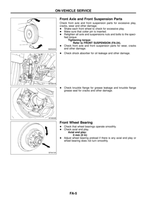
3. Check front wheel bearings for looseness.
4. Check front suspension for looseness.
5. Check steering linkage for looseness.
6. Check that shock absorbers work properly.
7. Check vehicle posture (Unladen).
CAMBER, CASTER AND KINGPIN INCLINATION
Camber, caster and kingpin inclination are preset at factory
and cannot be adjusted.
1. Measure camber, caster and kingpin inclination of both right
and left wheels with a suitable alignment gauge.
Camber, Caster and Kingpin inclination:
Refer to SDS (FA-27).
2. If camber, caster or kingpin inclination is not within
speci®cation, inspect front suspension parts. Replace damaged
or worn out parts.
SFA417A
SFA418AA
SFA356B
SFA894
ON-VEHICLE SERVICE
Front Wheel Bearing (Cont'd)
FA-8
Page 10 of 29

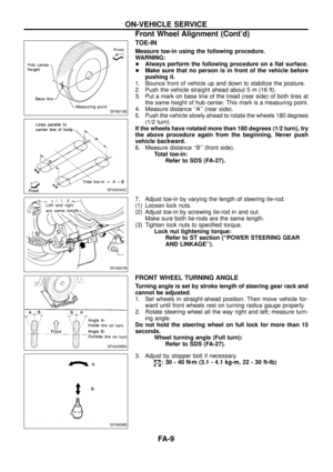
TOE-IN
Measure toe-in using the following procedure.
WARNING:
+Always perform the following procedure on a ¯at surface.
+Make sure that no person is in front of the vehicle before
pushing it.
1. Bounce front of vehicle up and down to stabilize the posture.
2. Push the vehicle straight ahead about 5 m (16 ft).
3. Put a mark on base line of the tread (rear side) of both tires at
the same height of hub center. This mark is a measuring point.
4. Measure distance ``A'' (rear side).
5. Push the vehicle slowly ahead to rotate the wheels 180 degrees
(1/2 turn).
If the wheels have rotated more than 180 degrees (1/2 turn), try
the above procedure again from the beginning. Never push
vehicle backward.
6. Measure distance ``B'' (front side).
Total toe-in:
Refer to SDS (FA-27).
7. Adjust toe-in by varying the length of steering tie-rod.
(1) Loosen lock nuts.
(2) Adjust toe-in by screwing tie-rod in and out.
Make sure both tie-rods are the same length.
(3) Tighten lock nuts to speci®ed torque.
Lock nut tightening torque:
Refer to ST section (``POWER STEERING GEAR
AND LINKAGE'').
FRONT WHEEL TURNING ANGLE
Turning angle is set by stroke length of steering gear rack and
cannot be adjusted.
1. Set wheels in straight-ahead position. Then move vehicle for-
ward until front wheels rest on turning radius gauge properly.
2. Rotate steering wheel all the way right and left; measure turn-
ing angle.
Do not hold the steering wheel on full lock for more than 15
seconds.
Wheel turning angle (Full turn):
Refer to SDS (FA-27).
3. Adjust by stopper bolt if necessary.
:30-40Nzm (3.1 - 4.1 kg-m, 22 - 30 ft-lb)
SFA614B
SFA234AC
SFA857B
SFA439BA
SFA858B
ON-VEHICLE SERVICE
Front Wheel Alignment (Cont'd)
FA-9
Page 11 of 29
SFA859B
FRONT AXLE Ð Drive ¯ange and Free-running Hub
FA-10
Page 12 of 29
Removal
1. Set knob of manual-lock free-running hub to the ``FREE'' posi-
tion.
2. Loosen bolts and remove free-running hub assembly.
3. Remove snap ring and take off drive clutch.
4. Take out bushing and spacer from wheel hub.
SFA427AA
SFA428A
SFA187
SFA188
SFA189
FRONT AXLE Ð Manual-lock Free-running Hub
FA-11
Page 13 of 29
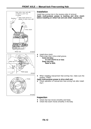
Installation
Install free-running hub in the reverse order of removal.
Apply multi-purpose grease to bushing and drive clutch
before installing on wheel hub and axle shaft, respectively.
+Install drive clutch.
+Place snap ring in drive shaft groove.
Axial end play:
0.4 mm (0.016 in) or less
Snap ring size:
Refer to SDS.
+When installing manual-lock free-running hub, make sure the
position ``FREE''.
Apply multi-purpose grease to drive shaft end.
+Check operation of manual-lock free-running hub after install-
ing it.
Inspection
+Check that hub moves smoothly and freely.
+Check that clutch moves smoothly in the body.
SFA860B
SFA200
SFA428A
FRONT AXLE Ð Manual-lock Free-running Hub
FA-12
Page 14 of 29

Removal
1. Set the auto-lock free-running hub at the condition ``LOCK''.
2. Remove auto-lock free-running hub assembly.
3. Remove snap ring.
4. Remove spindle washer and thrust washer.
5. After installing auto-lock free-running hub, check operation of it.
When installing it, apply recommended grease to drive shaft
end.
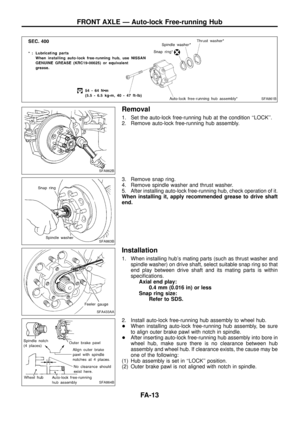
Installation
1. When installing hub's mating parts (such as thrust washer and
spindle washer) on drive shaft, select suitable snap ring so that
end play between drive shaft and its mating parts is within
speci®cations.
Axial end play:
0.4 mm (0.016 in) or less
Snap ring size:
Refer to SDS.
2. Install auto-lock free-running hub assembly to wheel hub.
+When installing auto-lock free-running hub assembly, be sure
to align outer brake pawl with notch in spindle.
+After inserting auto-lock free-running hub assembly into bore in
wheel hub, make sure there is no clearance between hub
assembly and wheel hub. If clearance exists, the cause may be
one of the following:
(1) Hub assembly is set in ``LOCK'' position.
(2) Outer brake pawl is not aligned with notch in spindle.
SFA861B
SFA862B
SFA863B
SFA433AA
SFA864B
FRONT AXLE Ð Auto-lock Free-running Hub
FA-13
Page 15 of 29

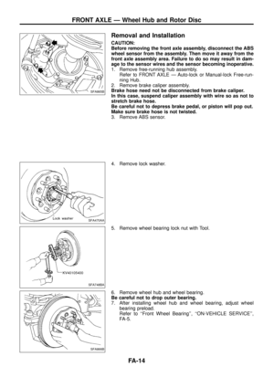
Removal and Installation
CAUTION:
Before removing the front axle assembly, disconnect the ABS
wheel sensor from the assembly. Then move it away from the
front axle assembly area. Failure to do so may result in dam-
age to the sensor wires and the sensor becoming inoperative.
1. Remove free-running hub assembly.
Refer to FRONT AXLE Ð Auto-lock or Manual-lock Free-run-
ning Hub.
2. Remove brake caliper assembly.
Brake hose need not be disconnected from brake caliper.
In this case, suspend caliper assembly with wire so as not to
stretch brake hose.
Be careful not to depress brake pedal, or piston will pop out.
Make sure brake hose is not twisted.
3. Remove ABS sensor.
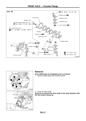
4. Remove lock washer.
5. Remove wheel bearing lock nut with Tool.
6. Remove wheel hub and wheel bearing.
Be careful not to drop outer bearing.
7. After installing wheel hub and wheel bearing, adjust wheel
bearing preload.
Refer to ``Front Wheel Bearing'', ``ON-VEHICLE SERVICE'',
FA-5.
SFA865B
SFA470AA
SFA748BA
SFA866B
FRONT AXLE Ð Wheel Hub and Rotor Disc
FA-14
Page 16 of 29
8. Separate brake disc to hub.
Inspection
Thoroughly clean wheel bearings and wheel hub.
WHEEL BEARING
+Make sure wheel bearing rolls freely and is free from noise,
crack, pitting or wear.
WHEEL HUB
+Check wheel hub for crack by using a magnetic exploration or
dyeing test.
Assembly
1. Install bearing outer race with Tool until it seats in hub.
2. Install the sensor rotor using suitable drift and press. (Models
with ABS)
Always replace sensor rotor with new one.
Pay attention to the direction of front sensor rotor as shown in
®gure.
3. Pack multi-purpose grease to hub and hub cap.
SFA193
SFA435A
SFA197
SBR400DA
SFA469A
FRONT AXLE Ð Wheel Hub and Rotor Disc
Removal and Installation (Cont'd)
FA-15