Page 55 of 65
Assembly
PISTON
1. Install new snap ring on one side of piston pin hole.
2. Heat piston to 60 to 70ÉC (140 to 158ÉF) and assemble piston,
piston pin, connecting rod and new snap ring.
+Align the direction of piston and connecting rod.
+Numbers stamped on connecting rod and cap correspond
to each cylinder.
+After assembly, make sure connecting rod swings
smoothly.
3. Set piston rings as shown.
CAUTION:
+When piston rings are not replaced, make sure that piston
rings are mounted in their original positions.
+Install new piston rings either side up if there is no punch-
mark.
+Align piston rings so that end gaps are positioned as
shown.
CRANKSHAFT
1. Set main bearings in their proper positions on cylinder block
and main bearing cap.
+Con®rm that correct main bearings are selected by using
Method A or Method B. Refer to EM-52.
+Apply new engine oil to bearing surfaces.
SEM146B
SEM754B
SEM156B
SEM160B
SEM157B
CYLINDER BLOCK
EM-54
Page 56 of 65

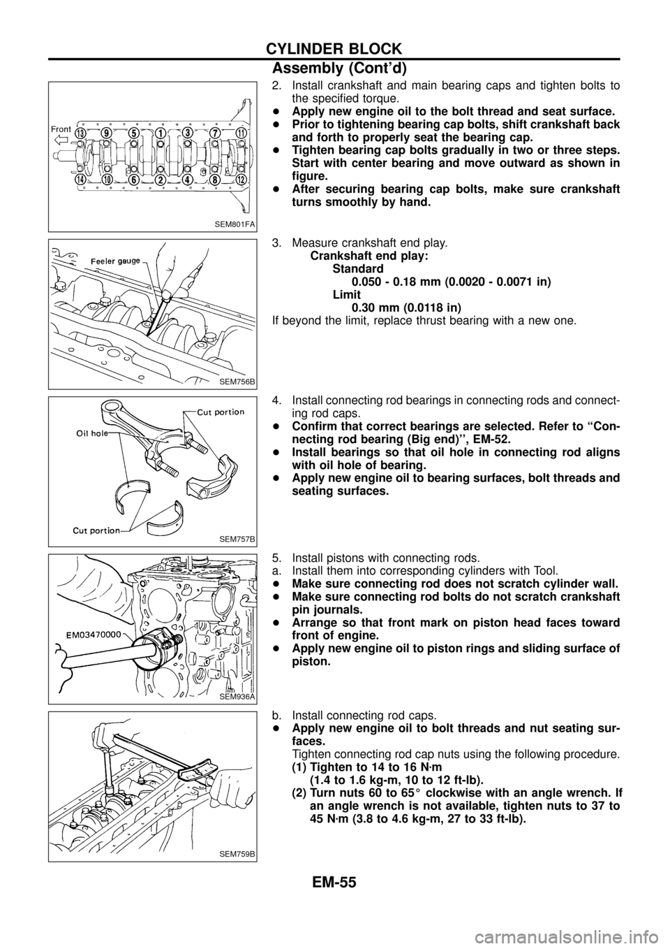
2. Install crankshaft and main bearing caps and tighten bolts to
the speci®ed torque.
+Apply new engine oil to the bolt thread and seat surface.
+Prior to tightening bearing cap bolts, shift crankshaft back
and forth to properly seat the bearing cap.
+Tighten bearing cap bolts gradually in two or three steps.
Start with center bearing and move outward as shown in
®gure.
+After securing bearing cap bolts, make sure crankshaft
turns smoothly by hand.
3. Measure crankshaft end play.
Crankshaft end play:
Standard
0.050 - 0.18 mm (0.0020 - 0.0071 in)
Limit
0.30 mm (0.0118 in)
If beyond the limit, replace thrust bearing with a new one.
4. Install connecting rod bearings in connecting rods and connect-
ing rod caps.
+Con®rm that correct bearings are selected. Refer to ``Con-
necting rod bearing (Big end)'', EM-52.
+Install bearings so that oil hole in connecting rod aligns
with oil hole of bearing.
+Apply new engine oil to bearing surfaces, bolt threads and
seating surfaces.
5. Install pistons with connecting rods.
a. Install them into corresponding cylinders with Tool.
+Make sure connecting rod does not scratch cylinder wall.
+Make sure connecting rod bolts do not scratch crankshaft
pin journals.
+Arrange so that front mark on piston head faces toward
front of engine.
+Apply new engine oil to piston rings and sliding surface of
piston.
b. Install connecting rod caps.
+Apply new engine oil to bolt threads and nut seating sur-
faces.
Tighten connecting rod cap nuts using the following procedure.
(1) Tighten to 14 to 16 Nzm
(1.4 to 1.6 kg-m, 10 to 12 ft-lb).
(2) Turn nuts 60 to 65É clockwise with an angle wrench. If
an angle wrench is not available, tighten nuts to 37 to
45 Nzm (3.8 to 4.6 kg-m, 27 to 33 ft-lb).
SEM801FA
SEM756B
SEM757B
SEM936A
SEM759B
CYLINDER BLOCK
Assembly (Cont'd)
EM-55
Page 58 of 65
General Speci®cations
Cylinder arrangement In-line 6
Displacement cm
3(cu in) 2,826 (172.44)
Bore and stroke mm (in) 85 x 83 (3.35 x 3.27)
Valve arrangement OHC
Firing order 1-5-3-6-2-4
Number of piston rings
Compression 2
Oil 1
Number of main bearings 7
Compression ratio 21.8
VALVE TIMING
Without warm-up three way catalyst
EM120Unit: degree
abcde f
248 220 7 33 8 60
Inspection and Adjustment
COMPRESSION PRESSURE
Unit: kPa (bar, kg/cm2, psi)/200 rpm
Compression pressure
Standard 3,040 (30.4, 31, 441)
Minimum 2,452 (24.5, 25, 356)
Differential limit between
cylinders490 (4.9, 5, 71)
CYLINDER HEAD
Unit: mm (in)
Standard Limit
Head surface distortionLess than
0.03 (0.0012)0.1 (0.004)
SEM795F
Nominal cylinder head height ``H''139.9 - 140.1
(5.508 - 5.516)
Resurfacing limit 0.1 (0.004)
SERVICE DATA AND SPECIFICATIONS (SDS)
EM-57
Page 62 of 65

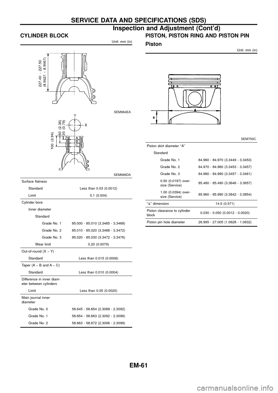
CYLINDER BLOCK
Unit: mm (in)
SEM964EA
SEM686DA
Surface ¯atness
Standard Less than 0.03 (0.0012)
Limit 0.1 (0.004)
Cylinder bore
Inner diameter
Standard
Grade No. 1 85.000 - 85.010 (3.3465 - 3.3468)
Grade No. 2 85.010 - 85.020 (3.3468 - 3.3472)
Grade No. 3 85.020 - 85.030 (3.3472 - 3.3476)
Wear limit 0.20 (0.0079)
Out-of-round (X þ Y)
Standard Less than 0.015 (0.0006)
Taper (A þ B and A þ C)
Standard Less than 0.010 (0.0004)
Difference in inner diam-
eter between cylinders
Limit Less than 0.05 (0.0020)
Main journal inner
diameter
Grade No. 0 58.645 - 58.654 (2.3089 - 2.3092)
Grade No. 1 58.654 - 58.663 (2.3092 - 2.3096)
Grade No. 2 58.663 - 58.672 (2.3096 - 2.3099)
PISTON, PISTON RING AND PISTON PIN
Piston
Unit: mm (in)
SEM750C
Piston skirt diameter ``A''
Standard
Grade No. 1 84.960 - 84.970 (3.3449 - 3.3453)
Grade No. 2 84.970 - 84.980 (3.3453 - 3.3457)
Grade No. 3 84.980 - 84.990 (3.3457 - 3.3461)
0.50 (0.0197) over-
size (Service)85.460 - 85.490 (3.3646 - 3.3657)
1.00 (0.0394) over-
size (Service)85.960 - 85.990 (3.3842 - 3.3854)
``a'' dimension 14.5 (0.571)
Piston clearance to cylinder
block0.030 - 0.050 (0.0012 - 0.0020)
Piston pin hole diameter 26.995 - 27.005 (1.0628 - 1.0632)
SERVICE DATA AND SPECIFICATIONS (SDS)
Inspection and Adjustment (Cont'd)
EM-61
Page 63 of 65

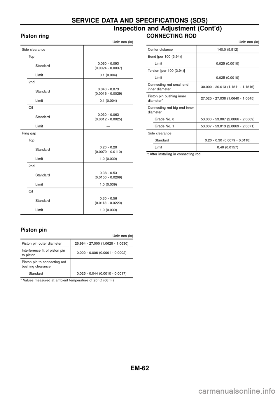
Piston ring
Unit: mm (in)
Side clearance
To p
Standard0.060 - 0.093
(0.0024 - 0.0037)
Limit 0.1 (0.004)
2nd
Standard0.040 - 0.073
(0.0016 - 0.0029)
Limit 0.1 (0.004)
Oil
Standard0.030 - 0.063
(0.0012 - 0.0025)
Limit Ð
Ring gap
To p
Standard0.20 - 0.28
(0.0079 - 0.0110)
Limit 1.0 (0.039)
2nd
Standard0.38 - 0.53
(0.0150 - 0.0209)
Limit 1.0 (0.039)
Oil
Standard0.30 - 0.56
(0.0118 - 0.0220)
Limit 1.0 (0.039)
Piston pin
Unit: mm (in)
Piston pin outer diameter 26.994 - 27.000 (1.0628 - 1.0630)
Interference ®t of piston pin
to piston0.002 - 0.006 (0.0001 - 0.0002)
Piston pin to connecting rod
bushing clearance
Standard 0.025 - 0.044 (0.0010 - 0.0017)
* Values measured at ambient temperature of 20ÉC (68ÉF)
CONNECTING ROD
Unit: mm (in)
Center distance 140.0 (5.512)
Bend [per 100 (3.94)]
Limit 0.025 (0.0010)
Torsion [per 100 (3.94)]
Limit 0.025 (0.0010)
Connecting rod small end
inner diameter30.000 - 30.013 (1.1811 - 1.1816)
Piston pin bushing inner
diameter*27.025 - 27.038 (1.0640 - 1.0645)
Connecting rod big end inner
diameter
Grade No. 0 53.000 - 53.007 (2.0866 - 2.0869)
Grade No. 1 53.007 - 53.013 (2.0869 - 2.0871)
Side clearance
Standard 0.20 - 0.30 (0.0079 - 0.0118)
Limit 0.40 (0.0157)
*: After installing in connecting rod
SERVICE DATA AND SPECIFICATIONS (SDS)
Inspection and Adjustment (Cont'd)
EM-62
Page:
< prev 1-8 9-16 17-24