Page 53 of 192

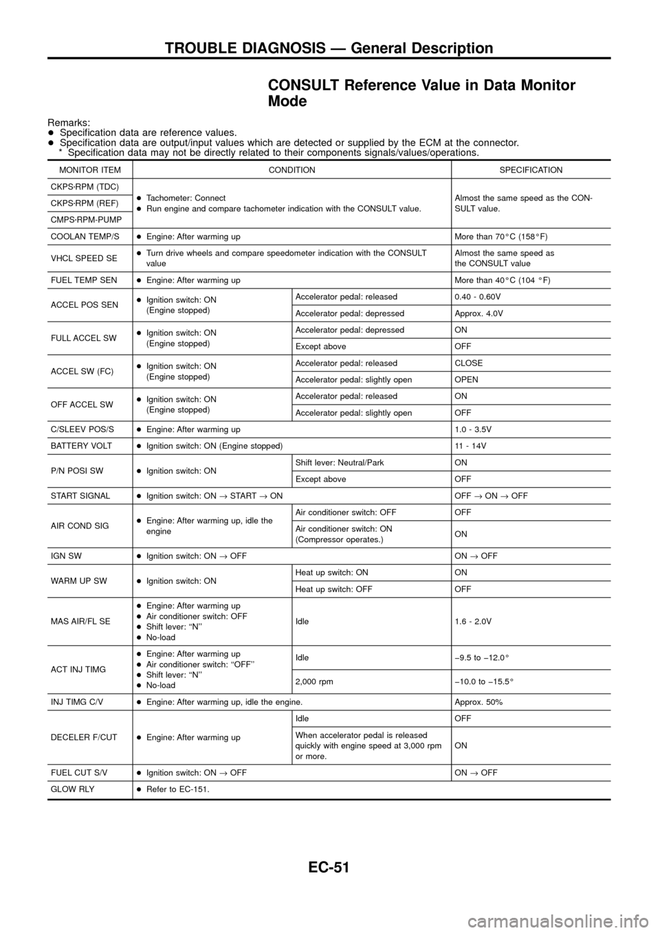
CONSULT Reference Value in Data Monitor
Mode
Remarks:
+Speci®cation data are reference values.
+Speci®cation data are output/input values which are detected or supplied by the ECM at the connector.
* Speci®cation data may not be directly related to their components signals/values/operations.
MONITOR ITEM CONDITION SPECIFICATION
CKPSzRPM (TDC)
+Tachometer: Connect
+Run engine and compare tachometer indication with the CONSULT value.Almost the same speed as the CON-
SULT value. CKPSzRPM (REF)
CMPSzRPM-PUMP
COOLAN TEMP/S+Engine: After warming up More than 70ÉC (158ÉF)
VHCL SPEED SE+Turn drive wheels and compare speedometer indication with the CONSULT
valueAlmost the same speed as
the CONSULT value
FUEL TEMP SEN+Engine: After warming up More than 40ÉC (104 ÉF)
ACCEL POS SEN+Ignition switch: ON
(Engine stopped)Accelerator pedal: released 0.40 - 0.60V
Accelerator pedal: depressed Approx. 4.0V
FULL ACCEL SW+Ignition switch: ON
(Engine stopped)Accelerator pedal: depressed ON
Except above OFF
ACCEL SW (FC)+Ignition switch: ON
(Engine stopped)Accelerator pedal: released CLOSE
Accelerator pedal: slightly open OPEN
OFF ACCEL SW+Ignition switch: ON
(Engine stopped)Accelerator pedal: released ON
Accelerator pedal: slightly open OFF
C/SLEEV POS/S+Engine: After warming up 1.0 - 3.5V
BATTERY VOLT+Ignition switch: ON (Engine stopped) 11 - 14V
P/N POSI SW+Ignition switch: ONShift lever: Neutral/Park ON
Except above OFF
START SIGNAL+Ignition switch: ON®START®ON OFF®ON®OFF
AIR COND SIG+Engine: After warming up, idle the
engineAir conditioner switch: OFF OFF
Air conditioner switch: ON
(Compressor operates.)ON
IGN SW+Ignition switch: ON®OFF ON®OFF
WARM UP SW+Ignition switch: ONHeat up switch: ON ON
Heat up switch: OFF OFF
MAS AIR/FL SE+Engine: After warming up
+Air conditioner switch: OFF
+Shift lever: ``N''
+No-loadIdle 1.6 - 2.0V
ACT INJ TIMG+Engine: After warming up
+Air conditioner switch: ``OFF''
+Shift lever: ``N''
+No-loadIdle þ9.5 to þ12.0É
2,000 rpm þ10.0 to þ15.5É
INJ TIMG C/V+Engine: After warming up, idle the engine. Approx. 50%
DECELER F/CUT+Engine: After warming upIdle OFF
When accelerator pedal is released
quickly with engine speed at 3,000 rpm
or more.ON
FUEL CUT S/V+Ignition switch: ON®OFF ON®OFF
GLOW RLY+Refer to EC-151.
TROUBLE DIAGNOSIS Ð General Description
EC-51
Page 85 of 192

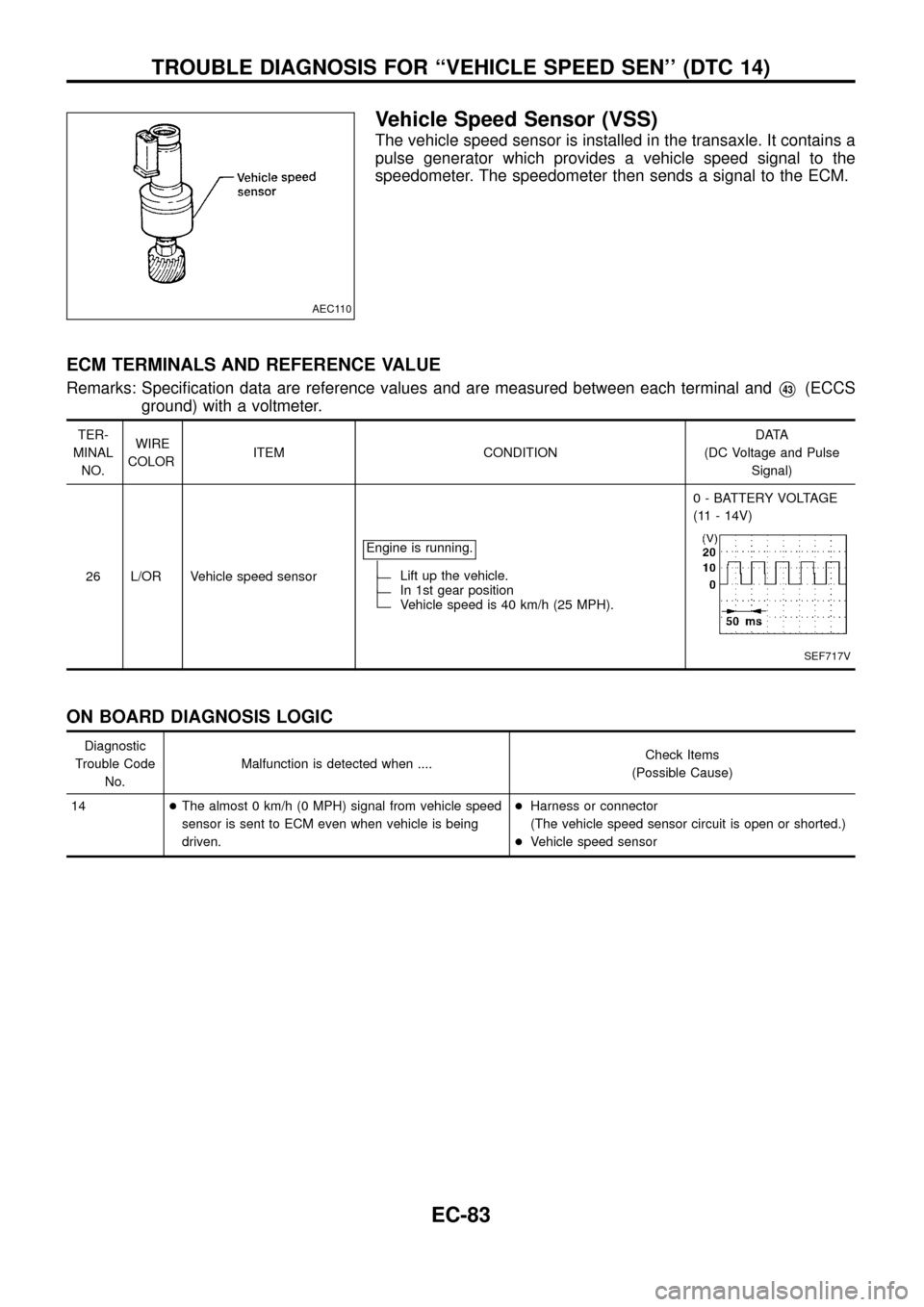
Vehicle Speed Sensor (VSS)
The vehicle speed sensor is installed in the transaxle. It contains a
pulse generator which provides a vehicle speed signal to the
speedometer. The speedometer then sends a signal to the ECM.
ECM TERMINALS AND REFERENCE VALUE
Remarks: Speci®cation data are reference values and are measured between each terminal andV43(ECCS
ground) with a voltmeter.
TER-
MINAL
NO.WIRE
COLORITEM CONDITIONDATA
(DC Voltage and Pulse
Signal)
26 L/OR Vehicle speed sensorEngine is running.
Lift up the vehicle.In 1st gear positionVehicle speed is 40 km/h (25 MPH).0 - BATTERY VOLTAGE
(11 - 14V)
SEF717V
ON BOARD DIAGNOSIS LOGIC
Diagnostic
Trouble Code
No.Malfunction is detected when ....Check Items
(Possible Cause)
14+The almost 0 km/h (0 MPH) signal from vehicle speed
sensor is sent to ECM even when vehicle is being
driven.+Harness or connector
(The vehicle speed sensor circuit is open or shorted.)
+Vehicle speed sensor
AEC110
TROUBLE DIAGNOSIS FOR ``VEHICLE SPEED SEN'' (DTC 14)
EC-83
Page 88 of 192

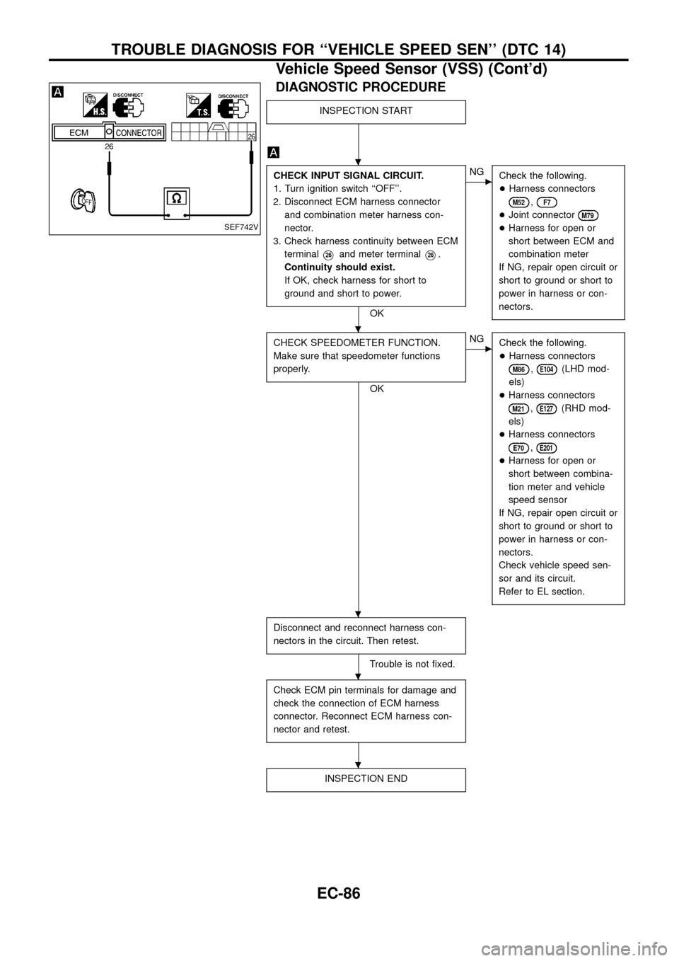
DIAGNOSTIC PROCEDURE
INSPECTION START
CHECK INPUT SIGNAL CIRCUIT.
1. Turn ignition switch ``OFF''.
2. Disconnect ECM harness connector
and combination meter harness con-
nector.
3. Check harness continuity between ECM
terminal
V26and meter terminalV26.
Continuity should exist.
If OK, check harness for short to
ground and short to power.
OK
cNG
Check the following.
+Harness connectors
M52,F7
+Joint connectorM79
+Harness for open or
short between ECM and
combination meter
If NG, repair open circuit or
short to ground or short to
power in harness or con-
nectors.
CHECK SPEEDOMETER FUNCTION.
Make sure that speedometer functions
properly.
OK
cNG
Check the following.
+Harness connectors
M86,E104(LHD mod-
els)
+Harness connectors
M21,E127(RHD mod-
els)
+Harness connectors
E70,E201
+Harness for open or
short between combina-
tion meter and vehicle
speed sensor
If NG, repair open circuit or
short to ground or short to
power in harness or con-
nectors.
Check vehicle speed sen-
sor and its circuit.
Refer to EL section.
Disconnect and reconnect harness con-
nectors in the circuit. Then retest.
Trouble is not ®xed.
Check ECM pin terminals for damage and
check the connection of ECM harness
connector. Reconnect ECM harness con-
nector and retest.
INSPECTION END
SEF742V
.
.
.
.
.
TROUBLE DIAGNOSIS FOR ``VEHICLE SPEED SEN'' (DTC 14)
Vehicle Speed Sensor (VSS) (Cont'd)
EC-86