1998 NISSAN PATROL check engine
[x] Cancel search: check enginePage 8 of 192
Precautions
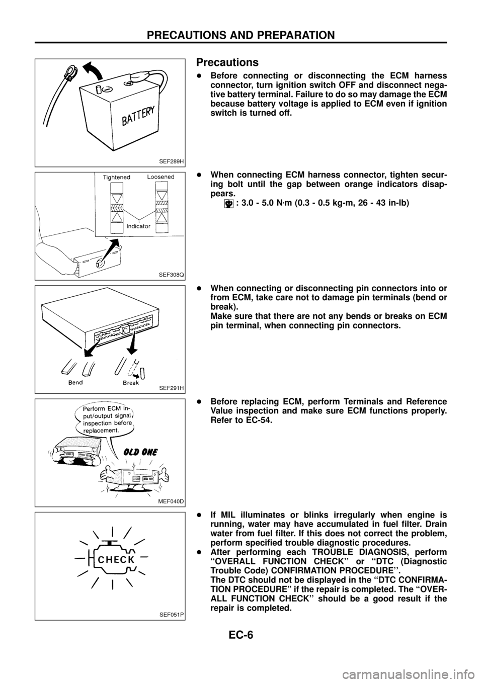
+Before connecting or disconnecting the ECM harness
connector, turn ignition switch OFF and disconnect nega-
tive battery terminal. Failure to do so may damage the ECM
because battery voltage is applied to ECM even if ignition
switch is turned off.
+When connecting ECM harness connector, tighten secur-
ing bolt until the gap between orange indicators disap-
pears.
: 3.0 - 5.0 Nzm (0.3 - 0.5 kg-m, 26 - 43 in-lb)
+When connecting or disconnecting pin connectors into or
from ECM, take care not to damage pin terminals (bend or
break).
Make sure that there are not any bends or breaks on ECM
pin terminal, when connecting pin connectors.
+Before replacing ECM, perform Terminals and Reference
Value inspection and make sure ECM functions properly.
Refer to EC-54.
+If MIL illuminates or blinks irregularly when engine is
running, water may have accumulated in fuel ®lter. Drain
water from fuel ®lter. If this does not correct the problem,
perform speci®ed trouble diagnostic procedures.
+After performing each TROUBLE DIAGNOSIS, perform
``OVERALL FUNCTION CHECK'' or ``DTC (Diagnostic
Trouble Code) CONFIRMATION PROCEDURE''.
The DTC should not be displayed in the ``DTC CONFIRMA-
TION PROCEDUREº if the repair is completed. The ``OVER-
ALL FUNCTION CHECK'' should be a good result if the
repair is completed.
SEF289H
SEF308Q
SEF291H
MEF040D
SEF051P
PRECAUTIONS AND PREPARATION
EC-6
Page 33 of 192
Malfunction Indicator Lamp (MIL)
1. The malfunction indicator lamp will light up when the ignition
switch is turned ON without the engine running. This is a bulb
check.
+If the malfunction indicator lamp does not light up, refer to EL
section (``WARNING LAMPS AND CHIME'') or see EC-188.
2. When the engine is started, the malfunction indicator lamp
should go off.
If the lamp remains on, the on board diagnostic system has
detected an engine system malfunction.
If MIL illuminates or blinks irregularly after starting engine,
water may have accumulated in fuel ®lter. Drain water from
fuel ®lter.
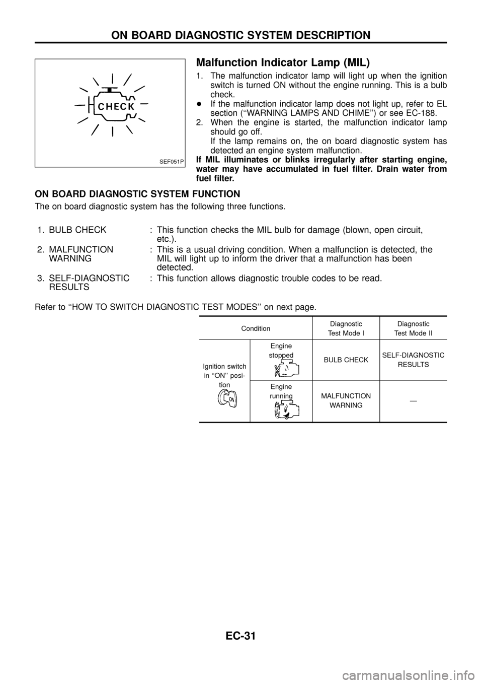
ON BOARD DIAGNOSTIC SYSTEM FUNCTION
The on board diagnostic system has the following three functions.
1. BULB CHECK : This function checks the MIL bulb for damage (blown, open circuit,
etc.).
2. MALFUNCTION
WARNING: This is a usual driving condition. When a malfunction is detected, the
MIL will light up to inform the driver that a malfunction has been
detected.
3. SELF-DIAGNOSTIC
RESULTS: This function allows diagnostic trouble codes to be read.
Refer to ``HOW TO SWITCH DIAGNOSTIC TEST MODES'' on next page.
ConditionDiagnostic
Test Mode IDiagnostic
Test Mode II
Ignition switch
in ``ON'' posi-
tion
Engine
stopped
BULB CHECKSELF-DIAGNOSTIC
RESULTS
Engine
running
MALFUNCTION
WARNINGÐ
SEF051P
ON BOARD DIAGNOSTIC SYSTEM DESCRIPTION
EC-31
Page 34 of 192
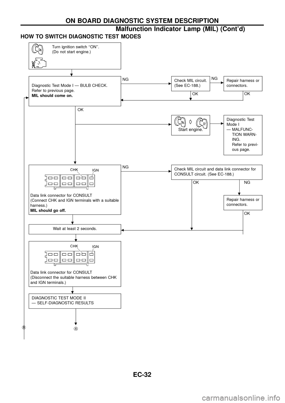
HOW TO SWITCH DIAGNOSTIC TEST MODES
Turn ignition switch ``ON''.
(Do not start engine.)
c
Diagnostic Test Mode I Ð BULB CHECK.
Refer to previous page.
MIL should come on.
.
OK
cNG
Check MIL circuit.
(See EC-188.)
OK
.
cNG
Repair harness or
connectors.
OK
b
cG
Start engine.
cDiagnostic Test
Mode I
Ð MALFUNC-
TION WARN-
ING.
Refer to previ-
ous page.
Data link connector for CONSULT
(Connect CHK and IGN terminals with a suitable
harness.)
MIL should go off.
cNG
Check MIL circuit and data link connector for
CONSULT circuit. (See EC-188.)
OK
.
NG
Repair harness or
connectors.
OK
Wait at least 2 seconds.
.b
Data link connector for CONSULT
(Disconnect the suitable harness between CHK
and IGN terminals.)
DIAGNOSTIC TEST MODE II
Ð SELF-DIAGNOSTIC RESULTS
.jBjA
.
.
.
.
ON BOARD DIAGNOSTIC SYSTEM DESCRIPTION
Malfunction Indicator Lamp (MIL) (Cont'd)
EC-32
Page 42 of 192
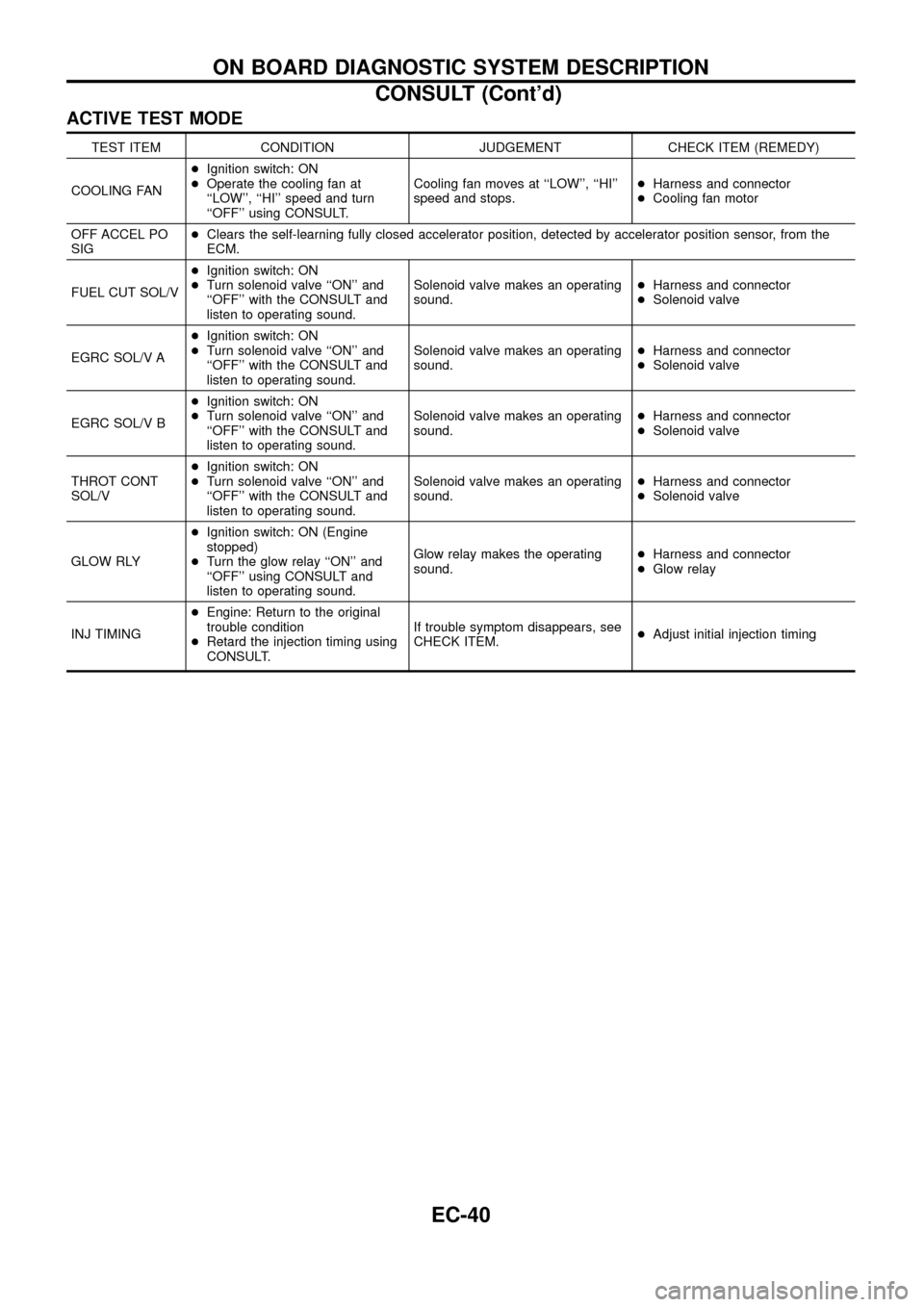
ACTIVE TEST MODE
TEST ITEM CONDITION JUDGEMENT CHECK ITEM (REMEDY)
COOLING FAN+Ignition switch: ON
+Operate the cooling fan at
``LOW'', ``HI'' speed and turn
``OFF'' using CONSULT.Cooling fan moves at ``LOW'', ``HI''
speed and stops.+Harness and connector
+Cooling fan motor
OFF ACCEL PO
SIG+Clears the self-learning fully closed accelerator position, detected by accelerator position sensor, from the
ECM.
FUEL CUT SOL/V+Ignition switch: ON
+Turn solenoid valve ``ON'' and
``OFF'' with the CONSULT and
listen to operating sound.Solenoid valve makes an operating
sound.+Harness and connector
+Solenoid valve
EGRC SOL/V A+Ignition switch: ON
+Turn solenoid valve ``ON'' and
``OFF'' with the CONSULT and
listen to operating sound.Solenoid valve makes an operating
sound.+Harness and connector
+Solenoid valve
EGRC SOL/V B+Ignition switch: ON
+Turn solenoid valve ``ON'' and
``OFF'' with the CONSULT and
listen to operating sound.Solenoid valve makes an operating
sound.+Harness and connector
+Solenoid valve
THROT CONT
SOL/V+Ignition switch: ON
+Turn solenoid valve ``ON'' and
``OFF'' with the CONSULT and
listen to operating sound.Solenoid valve makes an operating
sound.+Harness and connector
+Solenoid valve
GLOW RLY+Ignition switch: ON (Engine
stopped)
+Turn the glow relay ``ON'' and
``OFF'' using CONSULT and
listen to operating sound.Glow relay makes the operating
sound.+Harness and connector
+Glow relay
INJ TIMING+Engine: Return to the original
trouble condition
+Retard the injection timing using
CONSULT.If trouble symptom disappears, see
CHECK ITEM.+Adjust initial injection timing
ON BOARD DIAGNOSTIC SYSTEM DESCRIPTION
CONSULT (Cont'd)
EC-40
Page 44 of 192
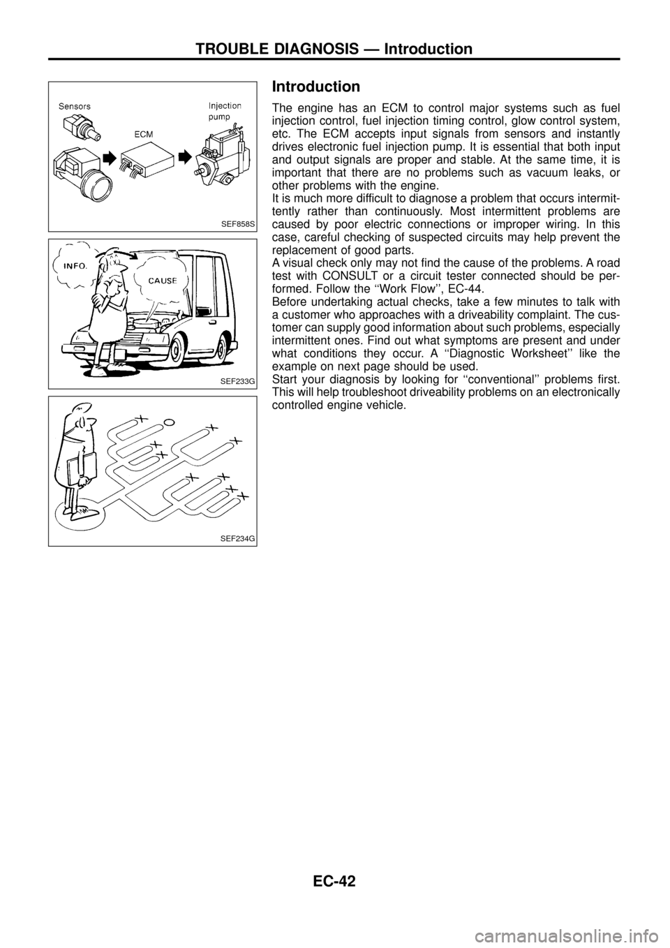
Introduction
The engine has an ECM to control major systems such as fuel
injection control, fuel injection timing control, glow control system,
etc. The ECM accepts input signals from sensors and instantly
drives electronic fuel injection pump. It is essential that both input
and output signals are proper and stable. At the same time, it is
important that there are no problems such as vacuum leaks, or
other problems with the engine.
It is much more difficult to diagnose a problem that occurs intermit-
tently rather than continuously. Most intermittent problems are
caused by poor electric connections or improper wiring. In this
case, careful checking of suspected circuits may help prevent the
replacement of good parts.
A visual check only may not ®nd the cause of the problems. A road
test with CONSULT or a circuit tester connected should be per-
formed. Follow the ``Work Flow'', EC-44.
Before undertaking actual checks, take a few minutes to talk with
a customer who approaches with a driveability complaint. The cus-
tomer can supply good information about such problems, especially
intermittent ones. Find out what symptoms are present and under
what conditions they occur. A ``Diagnostic Worksheet'' like the
example on next page should be used.
Start your diagnosis by looking for ``conventional'' problems ®rst.
This will help troubleshoot driveability problems on an electronically
controlled engine vehicle.
SEF858S
SEF233G
SEF234G
TROUBLE DIAGNOSIS Ð Introduction
EC-42
Page 47 of 192
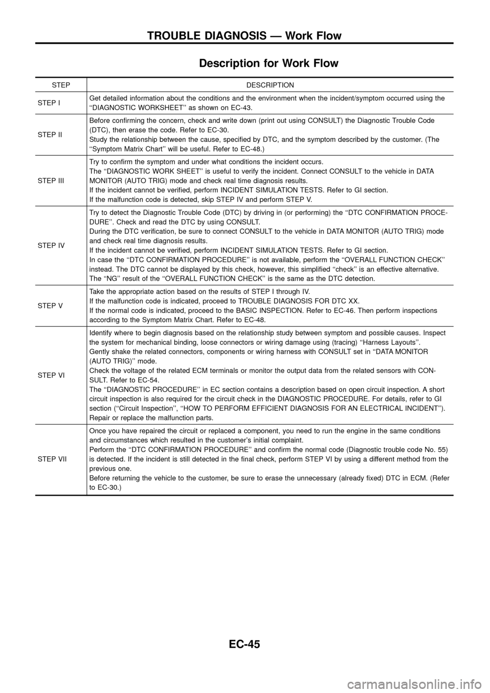
Description for Work Flow
STEP DESCRIPTION
STEP IGet detailed information about the conditions and the environment when the incident/symptom occurred using the
``DIAGNOSTIC WORKSHEET'' as shown on EC-43.
STEP IIBefore con®rming the concern, check and write down (print out using CONSULT) the Diagnostic Trouble Code
(DTC), then erase the code. Refer to EC-30.
Study the relationship between the cause, speci®ed by DTC, and the symptom described by the customer. (The
``Symptom Matrix Chart'' will be useful. Refer to EC-48.)
STEP IIITry to con®rm the symptom and under what conditions the incident occurs.
The ``DIAGNOSTIC WORK SHEET'' is useful to verify the incident. Connect CONSULT to the vehicle in DATA
MONITOR (AUTO TRIG) mode and check real time diagnosis results.
If the incident cannot be veri®ed, perform INCIDENT SIMULATION TESTS. Refer to GI section.
If the malfunction code is detected, skip STEP IV and perform STEP V.
STEP IVTry to detect the Diagnostic Trouble Code (DTC) by driving in (or performing) the ``DTC CONFIRMATION PROCE-
DURE''. Check and read the DTC by using CONSULT.
During the DTC veri®cation, be sure to connect CONSULT to the vehicle in DATA MONITOR (AUTO TRIG) mode
and check real time diagnosis results.
If the incident cannot be veri®ed, perform INCIDENT SIMULATION TESTS. Refer to GI section.
In case the ``DTC CONFIRMATION PROCEDURE'' is not available, perform the ``OVERALL FUNCTION CHECK''
instead. The DTC cannot be displayed by this check, however, this simpli®ed ``check'' is an effective alternative.
The ``NG'' result of the ``OVERALL FUNCTION CHECK'' is the same as the DTC detection.
STEP VTake the appropriate action based on the results of STEP I through IV.
If the malfunction code is indicated, proceed to TROUBLE DIAGNOSIS FOR DTC XX.
If the normal code is indicated, proceed to the BASIC INSPECTION. Refer to EC-46. Then perform inspections
according to the Symptom Matrix Chart. Refer to EC-48.
STEP VIIdentify where to begin diagnosis based on the relationship study between symptom and possible causes. Inspect
the system for mechanical binding, loose connectors or wiring damage using (tracing) ``Harness Layouts''.
Gently shake the related connectors, components or wiring harness with CONSULT set in ``DATA MONITOR
(AUTO TRIG)'' mode.
Check the voltage of the related ECM terminals or monitor the output data from the related sensors with CON-
SULT. Refer to EC-54.
The ``DIAGNOSTIC PROCEDURE'' in EC section contains a description based on open circuit inspection. A short
circuit inspection is also required for the circuit check in the DIAGNOSTIC PROCEDURE. For details, refer to GI
section (``Circuit Inspection'', ``HOW TO PERFORM EFFICIENT DIAGNOSIS FOR AN ELECTRICAL INCIDENT'').
Repair or replace the malfunction parts.
STEP VIIOnce you have repaired the circuit or replaced a component, you need to run the engine in the same conditions
and circumstances which resulted in the customer's initial complaint.
Perform the ``DTC CONFIRMATION PROCEDURE'' and con®rm the normal code (Diagnostic trouble code No. 55)
is detected. If the incident is still detected in the ®nal check, perform STEP VI by using a different method from the
previous one.
Before returning the vehicle to the customer, be sure to erase the unnecessary (already ®xed) DTC in ECM. (Refer
to EC-30.)
TROUBLE DIAGNOSIS Ð Work Flow
EC-45
Page 48 of 192
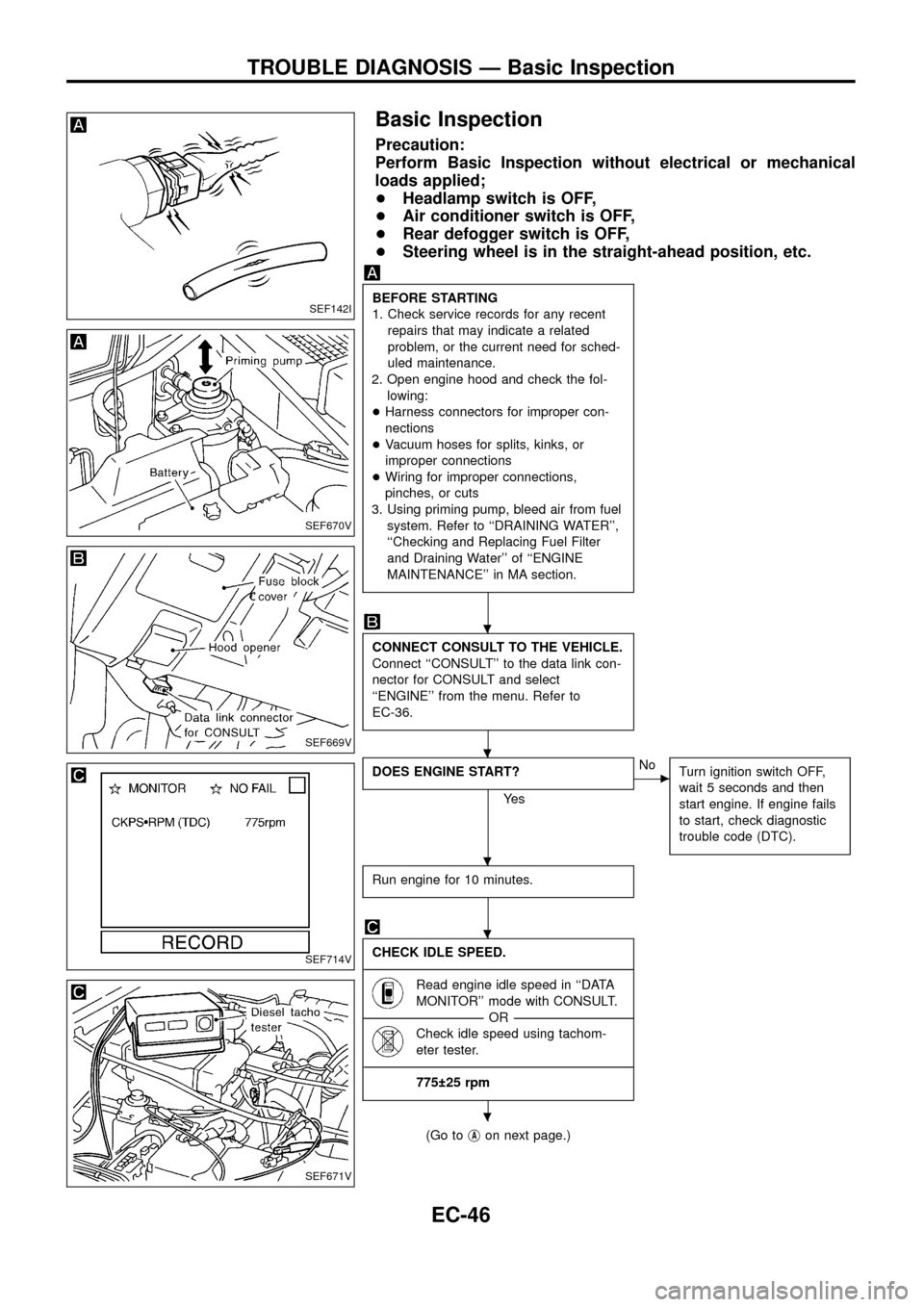
Basic Inspection
Precaution:
Perform Basic Inspection without electrical or mechanical
loads applied;
+Headlamp switch is OFF,
+Air conditioner switch is OFF,
+Rear defogger switch is OFF,
+Steering wheel is in the straight-ahead position, etc.
BEFORE STARTING
1. Check service records for any recent
repairs that may indicate a related
problem, or the current need for sched-
uled maintenance.
2. Open engine hood and check the fol-
lowing:
+Harness connectors for improper con-
nections
+Vacuum hoses for splits, kinks, or
improper connections
+Wiring for improper connections,
pinches, or cuts
3. Using priming pump, bleed air from fuel
system. Refer to ``DRAINING WATER'',
``Checking and Replacing Fuel Filter
and Draining Water'' of ``ENGINE
MAINTENANCE'' in MA section.
CONNECT CONSULT TO THE VEHICLE.
Connect ``CONSULT'' to the data link con-
nector for CONSULT and select
``ENGINE'' from the menu. Refer to
EC-36.
DOES ENGINE START?
Ye s
cNo
Turn ignition switch OFF,
wait 5 seconds and then
start engine. If engine fails
to start, check diagnostic
trouble code (DTC).
Run engine for 10 minutes.
CHECK IDLE SPEED.
----------------------------------------------------------------------------------------------------------------------------------------------------------------------------------------------------------------------------------------------------------------------------------------------------------------
Read engine idle speed in ``DATA
MONITOR'' mode with CONSULT.
--------------------------------------------------------------------------------------------------------------------------------------OR--------------------------------------------------------------------------------------------------------------------------------------
Check idle speed using tachom-
eter tester.
----------------------------------------------------------------------------------------------------------------------------------------------------------------------------------------------------------------------------------------------------------------------------------------------------------------
775 25 rpm
(Go tojAon next page.)
SEF142I
SEF670V
SEF669V
SEF714V
SEF671V
.
.
.
.
.
TROUBLE DIAGNOSIS Ð Basic Inspection
EC-46
Page 49 of 192
jA
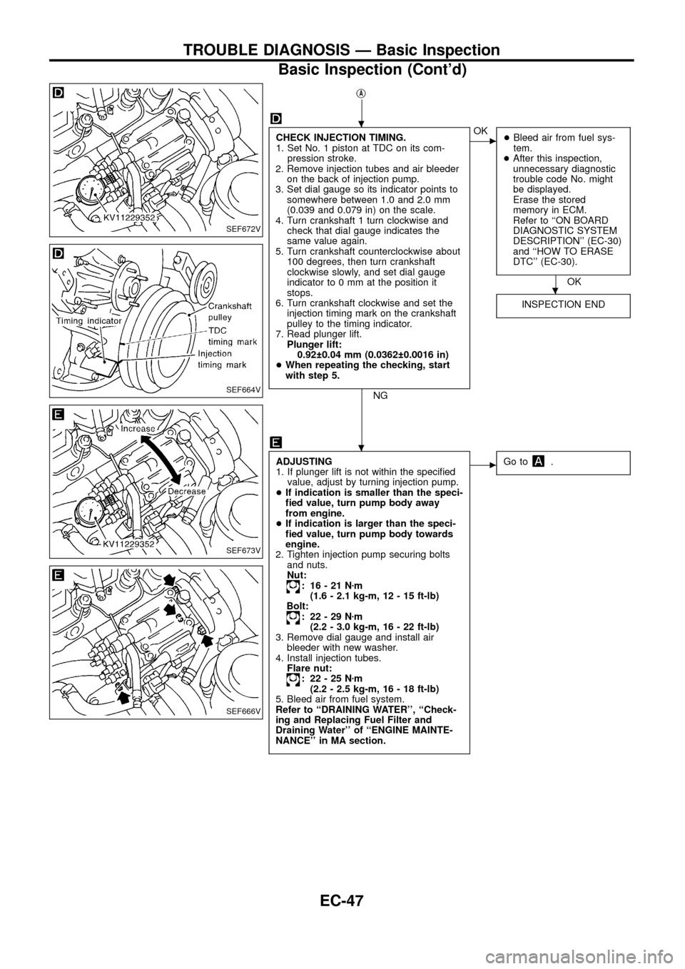
CHECK INJECTION TIMING.
1. Set No. 1 piston at TDC on its com-
pression stroke.
2. Remove injection tubes and air bleeder
on the back of injection pump.
3. Set dial gauge so its indicator points to
somewhere between 1.0 and 2.0 mm
(0.039 and 0.079 in) on the scale.
4. Turn crankshaft 1 turn clockwise and
check that dial gauge indicates the
same value again.
5. Turn crankshaft counterclockwise about
100 degrees, then turn crankshaft
clockwise slowly, and set dial gauge
indicator to 0 mm at the position it
stops.
6. Turn crankshaft clockwise and set the
injection timing mark on the crankshaft
pulley to the timing indicator.
7. Read plunger lift.
Plunger lift:
0.92 0.04 mm (0.0362 0.0016 in)
+When repeating the checking, start
with step 5.
NG
cOK
+Bleed air from fuel sys-
tem.
+After this inspection,
unnecessary diagnostic
trouble code No. might
be displayed.
Erase the stored
memory in ECM.
Refer to ``ON BOARD
DIAGNOSTIC SYSTEM
DESCRIPTION'' (EC-30)
and ``HOW TO ERASE
DTC'' (EC-30).
OK
INSPECTION END
ADJUSTING
1. If plunger lift is not within the speci®ed
value, adjust by turning injection pump.
+If indication is smaller than the speci-
®ed value, turn pump body away
from engine.
+If indication is larger than the speci-
®ed value, turn pump body towards
engine.
2. Tighten injection pump securing bolts
and nuts.
Nut:
: 16-21Nzm
(1.6 - 2.1 kg-m, 12 - 15 ft-lb)
Bolt:
: 22-29Nzm
(2.2 - 3.0 kg-m, 16 - 22 ft-lb)
3. Remove dial gauge and install air
bleeder with new washer.
4. Install injection tubes.
Flare nut:
: 22-25Nzm
(2.2 - 2.5 kg-m, 16 - 18 ft-lb)
5. Bleed air from fuel system.
Refer to ``DRAINING WATER'', ``Check-
ing and Replacing Fuel Filter and
Draining Water'' of ``ENGINE MAINTE-
NANCE'' in MA section.
cGo to.
SEF672V
SEF664V
SEF673V
SEF666V
.
.
.
TROUBLE DIAGNOSIS Ð Basic Inspection
Basic Inspection (Cont'd)
EC-47