1998 NISSAN PATROL check engine
[x] Cancel search: check enginePage 50 of 192
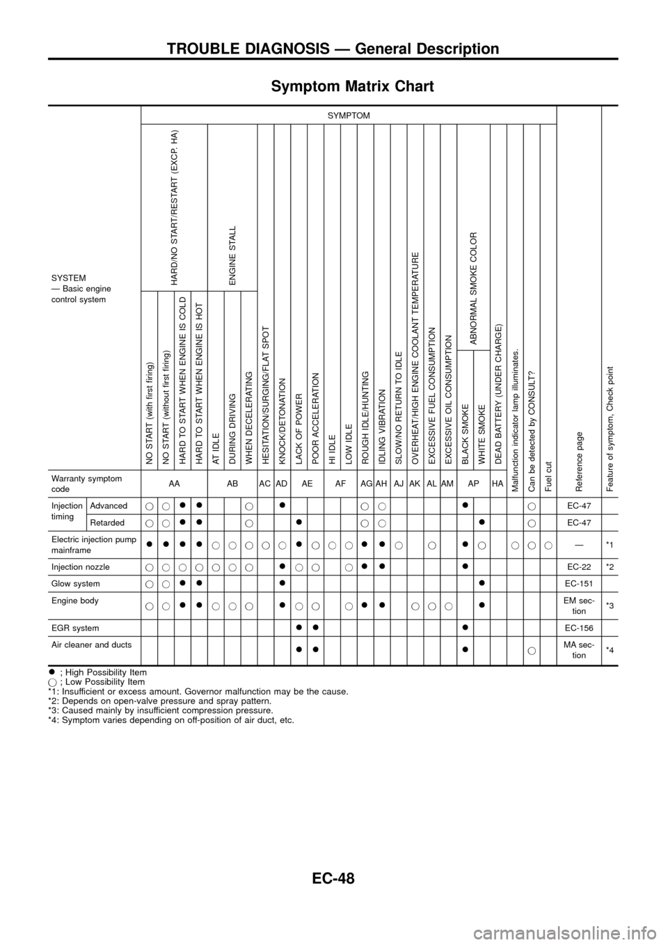
Symptom Matrix Chart
SYSTEM
Ð Basic engine
control systemSYMPTOM
Reference page
Feature of symptom, Check pointHARD/NO START/RESTART (EXCP. HA)
ENGINE STALL
HESITATION/SURGING/FLAT SPOT
KNOCK/DETONATION
LACK OF POWER
POOR ACCELERATION
HI IDLE
LOW IDLE
ROUGH IDLE/HUNTING
IDLING VIBRATION
SLOW/NO RETURN TO IDLE
OVERHEAT/HIGH ENGINE COOLANT TEMPERATURE
EXCESSIVE FUEL CONSUMPTION
EXCESSIVE OIL CONSUMPTION
ABNORMAL SMOKE COLOR
DEAD BATTERY (UNDER CHARGE)
Malfunction indicator lamp illuminates.
Can be detected by CONSULT?
Fuel cutNO START (with ®rst ®ring)
NO START (without ®rst ®ring)
HARD TO START WHEN ENGINE IS COLD
HARD TO START WHEN ENGINE IS HOT
AT IDLE
DURING DRIVING
WHEN DECELERATING
BLACK SMOKE
WHITE SMOKEWarranty symptom
codeAA AB AC AD AE AF AG AH AJ AK AL AM AP HA
Injection
timingAdvancedjj
++j+jj+jEC-47
Retardedjj
++j+jj+jEC-47
Electric injection pump
mainframe
++++jjjjj+jjj++jj+j jjjÐ*1
Injection nozzlejjjjjjj
+jj j++ +EC-22 *2
Glow systemjj
++ + +EC-151
Engine body
jj
++jjj+jj j++jjj+EM sec-
tion*3
EGR system
++ +EC-156
Air cleaner and ducts
++ +jMA sec-
tion*4
+; High Possibility Item
j; Low Possibility Item
*1: Insufficient or excess amount. Governor malfunction may be the cause.
*2: Depends on open-valve pressure and spray pattern.
*3: Caused mainly by insufficient compression pressure.
*4: Symptom varies depending on off-position of air duct, etc.
TROUBLE DIAGNOSIS Ð General Description
EC-48
Page 51 of 192
SYSTEM
Ð ECCS systemMalfunction
SYMPTOM
Reference
page Feature of symptom
Check point
HARD/NO START/
RESTART (EXCP. HA) ENGINE STALL HESITATION/SURGING/FLAT SPOT KNOCK/DETONATION
LACK OF POWER
POOR ACCELERATION
HI IDLE
LOW IDLE
ROUGH IDLE/HUNTING
IDLING VIBRATION
SLOW/NO RETURN TO IDLE
OVERHEAT/HIGH ENGINE COOLANT TEMPERATURE
EXCESSIVE FUEL CONSUMPTION
EXCESSIVE OIL CONSUMPTION ABNORMAL SMOKE COLOR
DEAD BATTERY (UNDER CHARGE) Malfunction indicator lamp illuminates.
Can be detected by CONSULT?
Fuel cut
NO START (with ®rst ®ring) NO START (without ®rst ®ring)
HARD TO START WHEN ENGINE IS COLD
HARD TO START WHEN ENGINE IS HOT
AT IDLE
DURING DRIVING
WHEN DECELERATINGBLACK SMOKE WHITE SMOKE
Warranty symptom code AA AB AC AD AE AF AG AH AJ AK AL AM AP HAECCS
Camshaft position sensor (PUMP) cir-
cuitopen, shortjj
EC-69Tachometer malfunction
noisejjjj jj
Mass air ¯ow sensor circuitopen, ground shortjjj j
EC-74
shortjjj
Engine coolant temperature sensor
circuitopen, shortjjj jjj jjEC-79Compensation according to
engine coolant temperature does
not function.
Vehicle speed sensor circuit open, shortjjEC-83
Control sleeve position sensor circuit open, shortjjjjjjEC-87
Adjustment resistor circuit open, shortj j jjjj j jEC-92
Electric governor circuitopen, ground shortj jjjjjj
EC-96
shortjj
Injection timing control valve circuitopen, shortjjj
EC-101Injection timing cannot be con-
trolled.
ground shortjj
Accelerator switch (FC) circuitopen, shortjjj
EC-106
ground shortjj
Charge air temperature sensor circuit open, shortjEC-122
Needle lift sensor circuit open, shortjjjEC-126
Fuel cut solenoid valve circuitopen, ground shortj jjjj
EC-130
shortjjjEngine runs on after turning igni-
tion switch OFF.
Fuel temperature sensor circuit open, shortjj jj jj j jj jEC-135Compensation for amount of fuel
injected according to fuel tem-
perature does not function.
Accelerator position sensor circuit open, shortjjj jjEC-139
Crankshaft position sensor (TDC) cir-
cuitopen, shortjj jj
EC-144
noisejjjjj
TROUBLE DIAGNOSIS Ð General Description
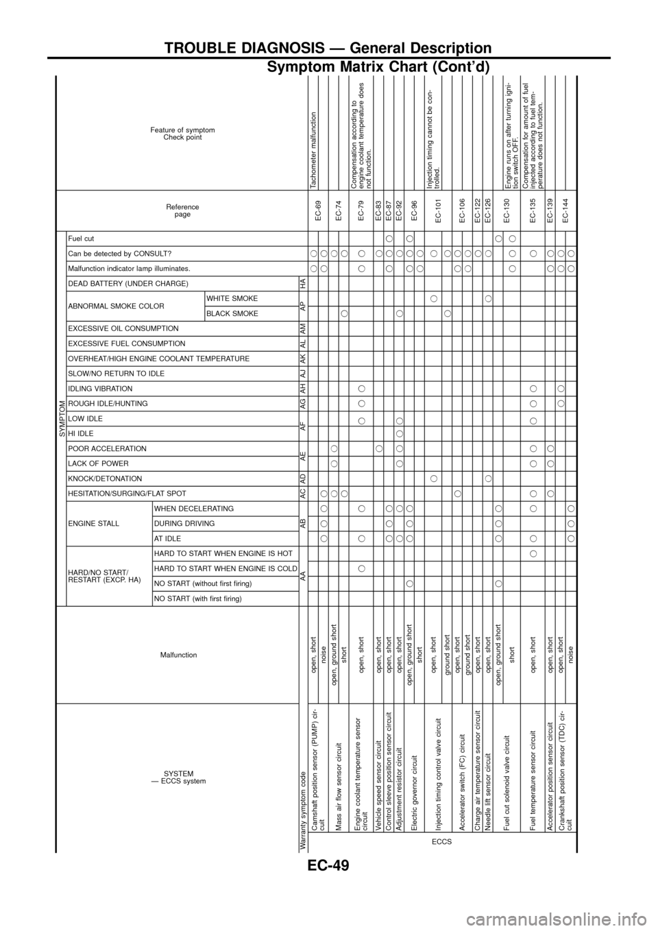
Symptom Matrix Chart (Cont'd)
EC-49
Page 52 of 192
SYSTEM
Ð ECCS systemMalfunction
SYMPTOM
Reference page Feature of symptom
Check point
HARD/NO START/
RESTART (EXCP. HA) ENGINE STALL HESITATION/SURGING/FLAT SPOT KNOCK/DETONATION
LACK OF POWER
POOR ACCELERATION
HI IDLE
LOW IDLE
ROUGH IDLE/HUNTING
IDLING VIBRATION
SLOW/NO RETURN TO IDLE
OVERHEAT/HIGH ENGINE COOLANT TEMPERATURE
EXCESSIVE FUEL CONSUMPTION
EXCESSIVE OIL CONSUMPTION ABNORMAL SMOKE COLOR
DEAD BATTERY (UNDER CHARGE) Malfunction indicator lamp illuminates.
Can be detected by CONSULT?
Fuel cut
NO START (with ®rst ®ring) NO START (without ®rst ®ring)
HARD TO START WHEN ENGINE IS COLD
HARD TO START WHEN ENGINE IS HOT
AT IDLE
DURING DRIVING
WHEN DECELERATINGBLACK SMOKE WHITE SMOKE
Warranty symptom code AA AB AC AD AE AF AG AH AJ AK AL AM AP HAECCS
Start signal circuit open, shortjjEC-163 Start control does not function.
Neutral position switch circuitopen, shortjjj
EC-170
ground shortjj
Accelerator position switch (Idle) cir-
cuitopen, ground shortjj j
EC-165
shortjjj jjAccelerator position sensor NG
signal is output.
Accelerator position switch (Full) cir-
cuitopen, shortjjj jjEC-165
Ignition switch circuitopenj jjj
EC-63
shortEngine does not stop.
Power supply for ECM circuitopenjjj
EC-63
shortjj
Throttle control solenoid valve circuitopen, short
EC-156Does not operate.
ground shortjj jDoes not stop operating.
EGRC-solenoid valve A, B circuitopen, short
EC-156
ground shortjDoes not stop operating.
Glow relay circuitopenjjjjj
EC-151Glow lamp does not turn on.
shortGlow lamp does not turn off.
ECCS relay (Self-shutoff) circuitopenjjjj
EC-63
shortjjGround short makes engine
unable to stop.
ECM, Connector circuit open, shortjjjjjjjjjjjjj jjjjjjjjjjjjEC-111
Air conditioner relay circuitopen
EC-187Air conditioner does not operate.
shortAir conditioner does not stop
operating.
Air conditioner switch circuitopen, ground short
EC-187Air conditioner does not stop
operating.
shortAir conditioner does not work.
TROUBLE DIAGNOSIS Ð General Description
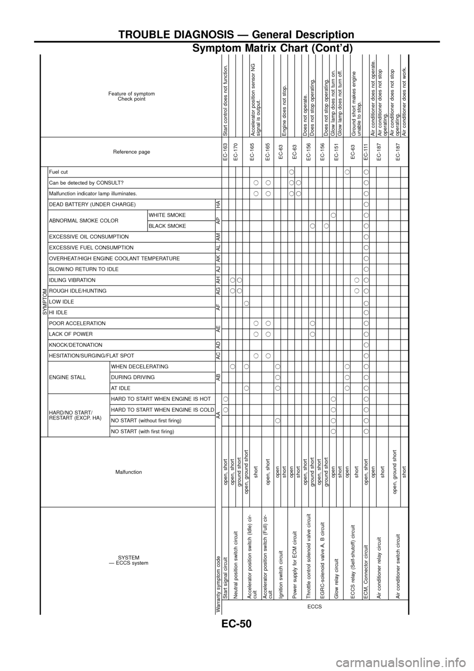
Symptom Matrix Chart (Cont'd)
EC-50
Page 68 of 192
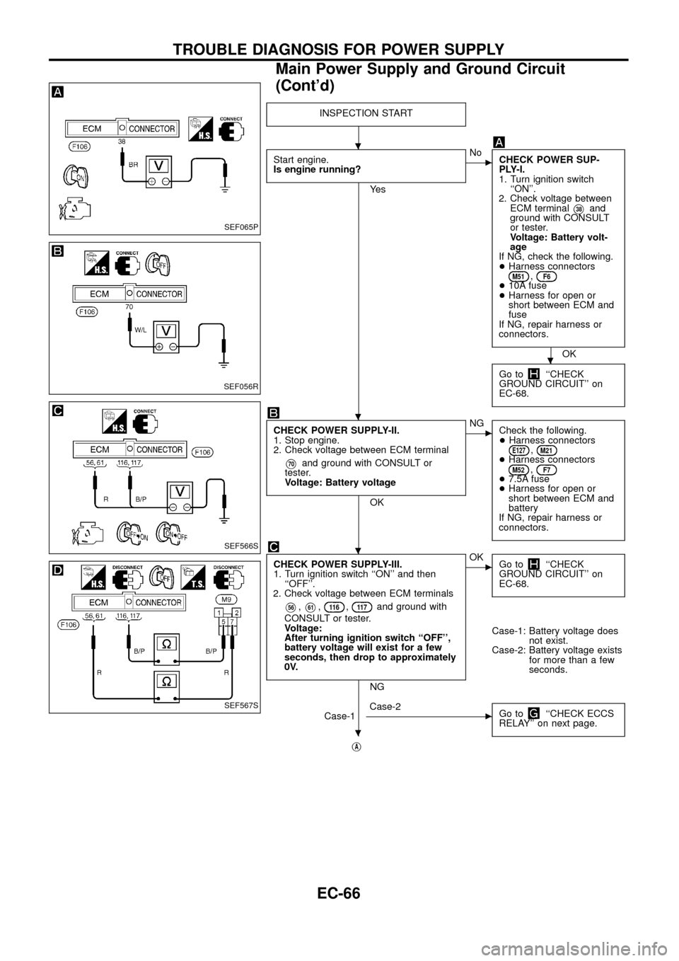
INSPECTION START
Start engine.
Is engine running?
Ye s
cNo
CHECK POWER SUP-
PLY-I.
1. Turn ignition switch
``ON''.
2. Check voltage between
ECM terminal
V38and
ground with CONSULT
or tester.
Voltage: Battery volt-
age
If NG, check the following.
+Harness connectors
M51,F6+10A fuse
+Harness for open or
short between ECM and
fuse
If NG, repair harness or
connectors.
OK
Go to
``CHECK
GROUND CIRCUIT'' on
EC-68.
CHECK POWER SUPPLY-II.
1. Stop engine.
2. Check voltage between ECM terminal
V70and ground with CONSULT or
tester.
Voltage: Battery voltage
OK
cNG
Check the following.
+Harness connectors
E127,M21+Harness connectorsM52,F7+7.5A fuse
+Harness for open or
short between ECM and
battery
If NG, repair harness or
connectors.
CHECK POWER SUPPLY-III.
1. Turn ignition switch ``ON'' and then
``OFF''.
2. Check voltage between ECM terminals
V56,V61,11 6,11 7and ground with
CONSULT or tester.
Voltage:
After turning ignition switch ``OFF'',
battery voltage will exist for a few
seconds, then drop to approximately
0V.
NG
cOK
Go to``CHECK
GROUND CIRCUIT'' on
EC-68.
Case-1: Battery voltage does
not exist.
Case-2: Battery voltage exists
for more than a few
seconds.
Case-1
cCase-2
Go to``CHECK ECCS
RELAY'' on next page.
jA
SEF065P
SEF056R
SEF566S
SEF567S
.
.
.
.
.
TROUBLE DIAGNOSIS FOR POWER SUPPLY
Main Power Supply and Ground Circuit
(Cont'd)
EC-66
Page 70 of 192
jB
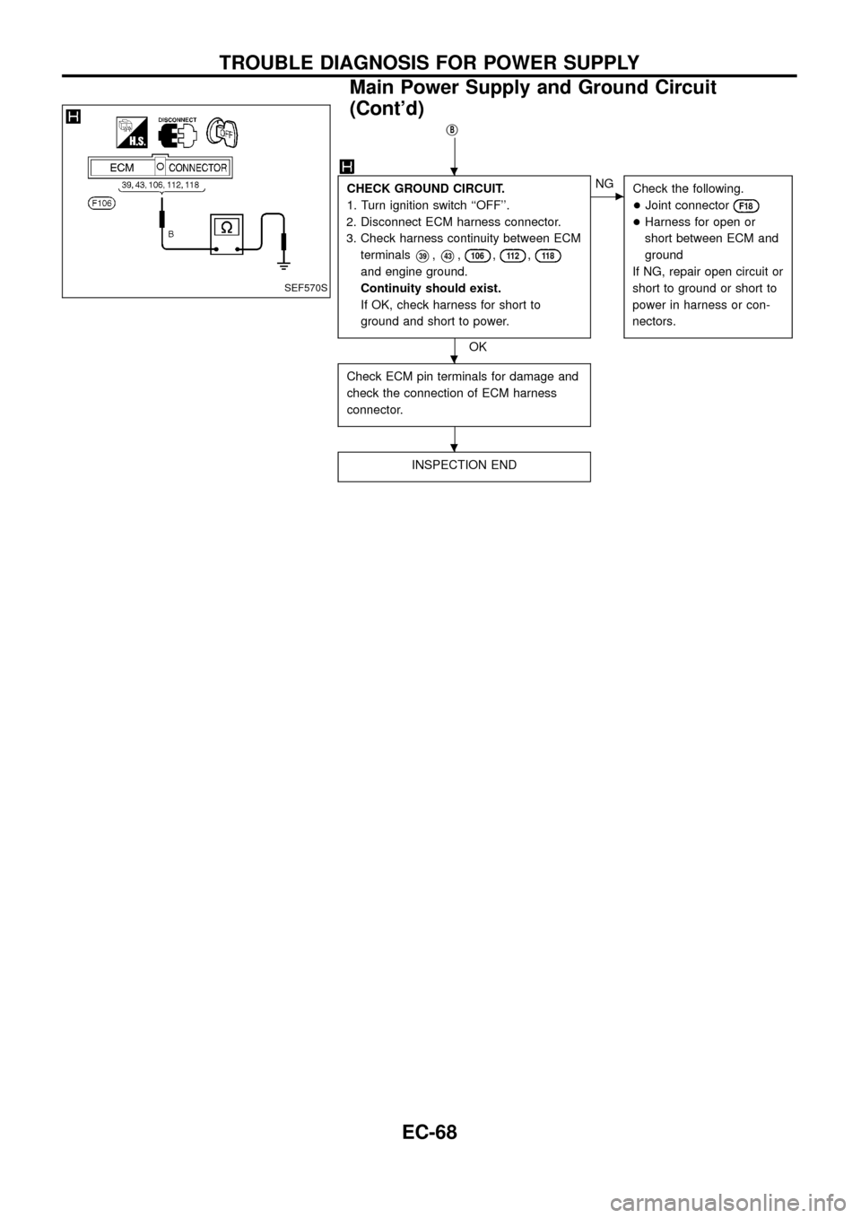
CHECK GROUND CIRCUIT.
1. Turn ignition switch ``OFF''.
2. Disconnect ECM harness connector.
3. Check harness continuity between ECM
terminals
V39,V43,106,11 2,11 8
and engine ground.
Continuity should exist.
If OK, check harness for short to
ground and short to power.
OK
cNG
Check the following.
+Joint connector
F18
+Harness for open or
short between ECM and
ground
If NG, repair open circuit or
short to ground or short to
power in harness or con-
nectors.
Check ECM pin terminals for damage and
check the connection of ECM harness
connector.
INSPECTION END
SEF570S
.
.
.
TROUBLE DIAGNOSIS FOR POWER SUPPLY
Main Power Supply and Ground Circuit
(Cont'd)
EC-68
Page 72 of 192
ON BOARD DIAGNOSIS LOGIC
Diagnostic
Trouble Code
No.Malfunction is detected when ....Check Items
(Possible cause)
11+An improper signal from the sensor is detected by
ECM during engine running.+Harness or connectors
[The camshaft position sensor (PUMP) circuit is open
or shorted.]
+Camshaft position sensor (PUMP)
DIAGNOSTIC TROUBLE CODE CONFIRMATION
PROCEDURE
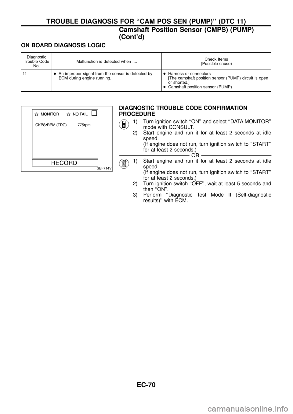
1) Turn ignition switch ``ON'' and select ``DATA MONITOR''
mode with CONSULT.
2) Start engine and run it for at least 2 seconds at idle
speed.
(If engine does not run, turn ignition switch to ``START''
for at least 2 seconds.)
-------------------------------------------------------------------------------------------------------------------------------------------------------------------------------------------------------------------------------------------------------OR-------------------------------------------------------------------------------------------------------------------------------------------------------------------------------------------------------------------------------------------------------
1) Start engine and run it for at least 2 seconds at idle
speed.
(If engine does not run, turn ignition switch to ``START''
for at least 2 seconds.)
2) Turn ignition switch ``OFF'', wait at least 5 seconds and
then ``ON''.
3) Perform ``Diagnostic Test Mode II (Self-diagnostic
results)'' with ECM.
SEF714V
TROUBLE DIAGNOSIS FOR ``CAM POS SEN (PUMP)'' (DTC 11)
Camshaft Position Sensor (CMPS) (PUMP)
(Cont'd)
EC-70
Page 74 of 192
DIAGNOSTIC PROCEDURE
INSPECTION START
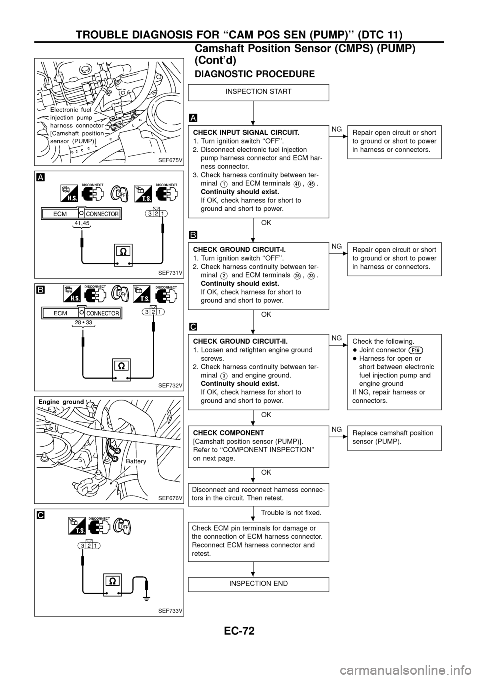
CHECK INPUT SIGNAL CIRCUIT.
1. Turn ignition switch ``OFF''.
2. Disconnect electronic fuel injection
pump harness connector and ECM har-
ness connector.
3. Check harness continuity between ter-
minal
V1and ECM terminalsV41,V45.
Continuity should exist.
If OK, check harness for short to
ground and short to power.
OK
cNG
Repair open circuit or short
to ground or short to power
in harness or connectors.
CHECK GROUND CIRCUIT-I.
1. Turn ignition switch ``OFF''.
2. Check harness continuity between ter-
minal
V2and ECM terminalsV28,V33.
Continuity should exist.
If OK, check harness for short to
ground and short to power.
OK
cNG
Repair open circuit or short
to ground or short to power
in harness or connectors.
CHECK GROUND CIRCUIT-II.
1. Loosen and retighten engine ground
screws.
2. Check harness continuity between ter-
minal
V3and engine ground.
Continuity should exist.
If OK, check harness for short to
ground and short to power.
OK
cNG
Check the following.
+Joint connector
F19
+Harness for open or
short between electronic
fuel injection pump and
engine ground
If NG, repair harness or
connectors.
CHECK COMPONENT
[Camshaft position sensor (PUMP)].
Refer to ``COMPONENT INSPECTION''
on next page.
OK
cNG
Replace camshaft position
sensor (PUMP).
Disconnect and reconnect harness connec-
tors in the circuit. Then retest.
Trouble is not ®xed.
Check ECM pin terminals for damage or
the connection of ECM harness connector.
Reconnect ECM harness connector and
retest.
INSPECTION END
SEF675V
SEF731V
SEF732V
SEF676V
SEF733V
.
.
.
.
.
.
.
TROUBLE DIAGNOSIS FOR ``CAM POS SEN (PUMP)'' (DTC 11)
Camshaft Position Sensor (CMPS) (PUMP)
(Cont'd)
EC-72
Page 76 of 192
Mass Air Flow Sensor (MAFS)
COMPONENT DESCRIPTION
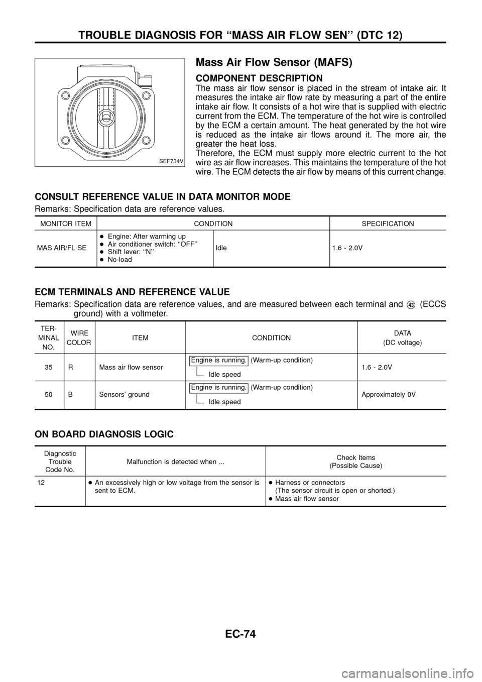
The mass air ¯ow sensor is placed in the stream of intake air. It
measures the intake air ¯ow rate by measuring a part of the entire
intake air ¯ow. It consists of a hot wire that is supplied with electric
current from the ECM. The temperature of the hot wire is controlled
by the ECM a certain amount. The heat generated by the hot wire
is reduced as the intake air ¯ows around it. The more air, the
greater the heat loss.
Therefore, the ECM must supply more electric current to the hot
wire as air ¯ow increases. This maintains the temperature of the hot
wire. The ECM detects the air ¯ow by means of this current change.
CONSULT REFERENCE VALUE IN DATA MONITOR MODE
Remarks: Speci®cation data are reference values.
MONITOR ITEM CONDITION SPECIFICATION
MAS AIR/FL SE+Engine: After warming up
+Air conditioner switch: ``OFF''
+Shift lever: ``N''
+No-loadIdle 1.6 - 2.0V
ECM TERMINALS AND REFERENCE VALUE
Remarks: Speci®cation data are reference values, and are measured between each terminal andV43(ECCS
ground) with a voltmeter.
TER-
MINAL
NO.WIRE
COLORITEM CONDITIONDATA
(DC voltage)
35 R Mass air ¯ow sensorEngine is running.
(Warm-up condition)
Idle speed1.6 - 2.0V
50 B Sensors' groundEngine is running.
(Warm-up condition)
Idle speedApproximately 0V
ON BOARD DIAGNOSIS LOGIC
Diagnostic
Trouble
Code No.Malfunction is detected when ...Check Items
(Possible Cause)
12+An excessively high or low voltage from the sensor is
sent to ECM.+Harness or connectors
(The sensor circuit is open or shorted.)
+Mass air ¯ow sensor
SEF734V
TROUBLE DIAGNOSIS FOR ``MASS AIR FLOW SEN'' (DTC 12)
EC-74