1998 NISSAN PATROL tachometer
[x] Cancel search: tachometerPage 51 of 192
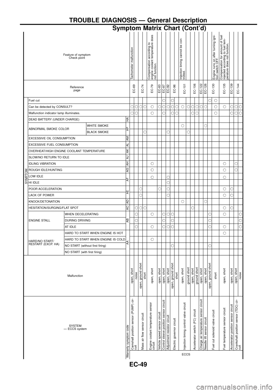
SYSTEM
Ð ECCS systemMalfunction
SYMPTOM
Reference
page Feature of symptom
Check point
HARD/NO START/
RESTART (EXCP. HA) ENGINE STALL HESITATION/SURGING/FLAT SPOT KNOCK/DETONATION
LACK OF POWER
POOR ACCELERATION
HI IDLE
LOW IDLE
ROUGH IDLE/HUNTING
IDLING VIBRATION
SLOW/NO RETURN TO IDLE
OVERHEAT/HIGH ENGINE COOLANT TEMPERATURE
EXCESSIVE FUEL CONSUMPTION
EXCESSIVE OIL CONSUMPTION ABNORMAL SMOKE COLOR
DEAD BATTERY (UNDER CHARGE) Malfunction indicator lamp illuminates.
Can be detected by CONSULT?
Fuel cut
NO START (with ®rst ®ring) NO START (without ®rst ®ring)
HARD TO START WHEN ENGINE IS COLD
HARD TO START WHEN ENGINE IS HOT
AT IDLE
DURING DRIVING
WHEN DECELERATINGBLACK SMOKE WHITE SMOKE
Warranty symptom code AA AB AC AD AE AF AG AH AJ AK AL AM AP HAECCS
Camshaft position sensor (PUMP) cir-
cuitopen, shortjj
EC-69Tachometer malfunction
noisejjjj jj
Mass air ¯ow sensor circuitopen, ground shortjjj j
EC-74
shortjjj
Engine coolant temperature sensor
circuitopen, shortjjj jjj jjEC-79Compensation according to
engine coolant temperature does
not function.
Vehicle speed sensor circuit open, shortjjEC-83
Control sleeve position sensor circuit open, shortjjjjjjEC-87
Adjustment resistor circuit open, shortj j jjjj j jEC-92
Electric governor circuitopen, ground shortj jjjjjj
EC-96
shortjj
Injection timing control valve circuitopen, shortjjj
EC-101Injection timing cannot be con-
trolled.
ground shortjj
Accelerator switch (FC) circuitopen, shortjjj
EC-106
ground shortjj
Charge air temperature sensor circuit open, shortjEC-122
Needle lift sensor circuit open, shortjjjEC-126
Fuel cut solenoid valve circuitopen, ground shortj jjjj
EC-130
shortjjjEngine runs on after turning igni-
tion switch OFF.
Fuel temperature sensor circuit open, shortjj jj jj j jj jEC-135Compensation for amount of fuel
injected according to fuel tem-
perature does not function.
Accelerator position sensor circuit open, shortjjj jjEC-139
Crankshaft position sensor (TDC) cir-
cuitopen, shortjj jj
EC-144
noisejjjjj
TROUBLE DIAGNOSIS Ð General Description
Symptom Matrix Chart (Cont'd)
EC-49
Page 53 of 192
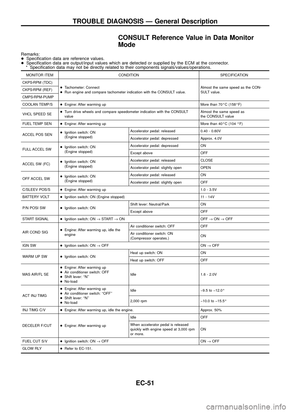
CONSULT Reference Value in Data Monitor
Mode
Remarks:
+Speci®cation data are reference values.
+Speci®cation data are output/input values which are detected or supplied by the ECM at the connector.
* Speci®cation data may not be directly related to their components signals/values/operations.
MONITOR ITEM CONDITION SPECIFICATION
CKPSzRPM (TDC)
+Tachometer: Connect
+Run engine and compare tachometer indication with the CONSULT value.Almost the same speed as the CON-
SULT value. CKPSzRPM (REF)
CMPSzRPM-PUMP
COOLAN TEMP/S+Engine: After warming up More than 70ÉC (158ÉF)
VHCL SPEED SE+Turn drive wheels and compare speedometer indication with the CONSULT
valueAlmost the same speed as
the CONSULT value
FUEL TEMP SEN+Engine: After warming up More than 40ÉC (104 ÉF)
ACCEL POS SEN+Ignition switch: ON
(Engine stopped)Accelerator pedal: released 0.40 - 0.60V
Accelerator pedal: depressed Approx. 4.0V
FULL ACCEL SW+Ignition switch: ON
(Engine stopped)Accelerator pedal: depressed ON
Except above OFF
ACCEL SW (FC)+Ignition switch: ON
(Engine stopped)Accelerator pedal: released CLOSE
Accelerator pedal: slightly open OPEN
OFF ACCEL SW+Ignition switch: ON
(Engine stopped)Accelerator pedal: released ON
Accelerator pedal: slightly open OFF
C/SLEEV POS/S+Engine: After warming up 1.0 - 3.5V
BATTERY VOLT+Ignition switch: ON (Engine stopped) 11 - 14V
P/N POSI SW+Ignition switch: ONShift lever: Neutral/Park ON
Except above OFF
START SIGNAL+Ignition switch: ON®START®ON OFF®ON®OFF
AIR COND SIG+Engine: After warming up, idle the
engineAir conditioner switch: OFF OFF
Air conditioner switch: ON
(Compressor operates.)ON
IGN SW+Ignition switch: ON®OFF ON®OFF
WARM UP SW+Ignition switch: ONHeat up switch: ON ON
Heat up switch: OFF OFF
MAS AIR/FL SE+Engine: After warming up
+Air conditioner switch: OFF
+Shift lever: ``N''
+No-loadIdle 1.6 - 2.0V
ACT INJ TIMG+Engine: After warming up
+Air conditioner switch: ``OFF''
+Shift lever: ``N''
+No-loadIdle þ9.5 to þ12.0É
2,000 rpm þ10.0 to þ15.5É
INJ TIMG C/V+Engine: After warming up, idle the engine. Approx. 50%
DECELER F/CUT+Engine: After warming upIdle OFF
When accelerator pedal is released
quickly with engine speed at 3,000 rpm
or more.ON
FUEL CUT S/V+Ignition switch: ON®OFF ON®OFF
GLOW RLY+Refer to EC-151.
TROUBLE DIAGNOSIS Ð General Description
EC-51
Page 57 of 192
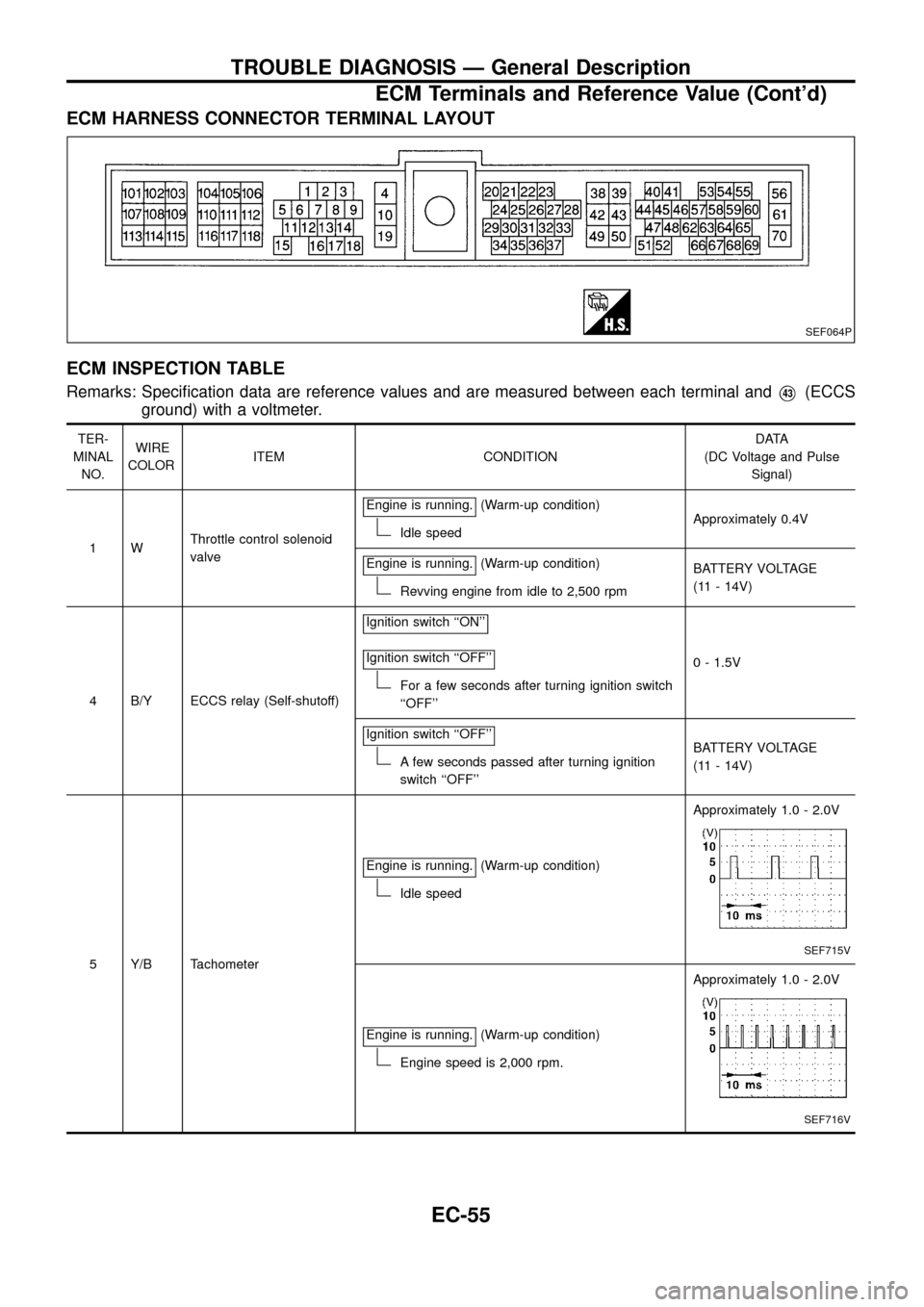
ECM HARNESS CONNECTOR TERMINAL LAYOUT
ECM INSPECTION TABLE
Remarks: Speci®cation data are reference values and are measured between each terminal andV43(ECCS
ground) with a voltmeter.
TER-
MINAL
NO.WIRE
COLORITEM CONDITIONDATA
(DC Voltage and Pulse
Signal)
1WThrottle control solenoid
valveEngine is running.
(Warm-up condition)
Idle speedApproximately 0.4V
Engine is running.
(Warm-up condition)
Revving engine from idle to 2,500 rpmBATTERY VOLTAGE
(11 - 14V)
4 B/Y ECCS relay (Self-shutoff)Ignition switch ``ON''
Ignition switch ``OFF''
For a few seconds after turning ignition switch
``OFF''0 - 1.5V
Ignition switch ``OFF''
A few seconds passed after turning ignition
switch ``OFF''BATTERY VOLTAGE
(11 - 14V)
5 Y/B TachometerEngine is running.
(Warm-up condition)
Idle speedApproximately 1.0 - 2.0V
SEF715V
Engine is running.(Warm-up condition)
Engine speed is 2,000 rpm.Approximately 1.0 - 2.0V
SEF716V
SEF064P
TROUBLE DIAGNOSIS Ð General Description
ECM Terminals and Reference Value (Cont'd)
EC-55
Page 71 of 192
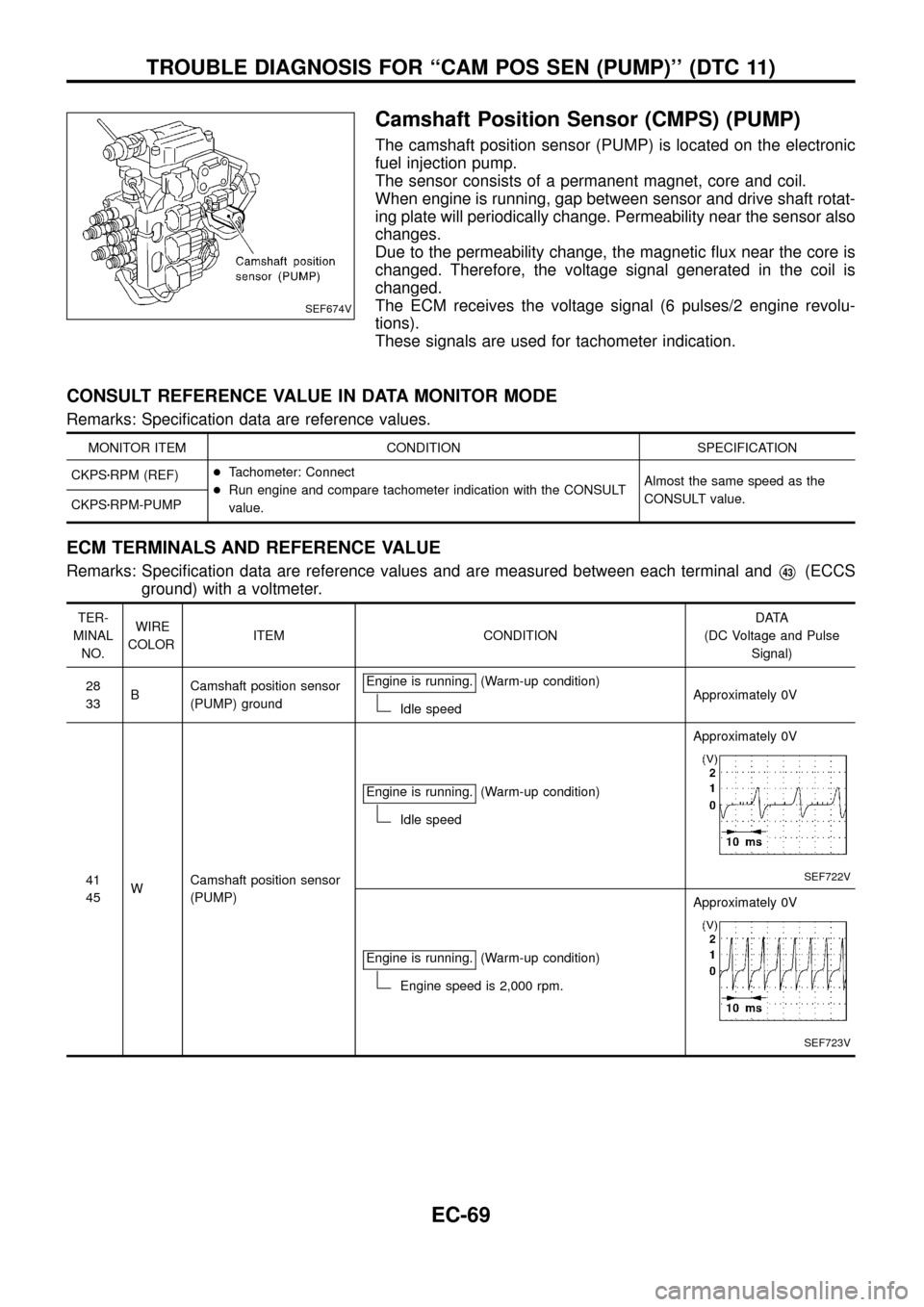
Camshaft Position Sensor (CMPS) (PUMP)
The camshaft position sensor (PUMP) is located on the electronic
fuel injection pump.
The sensor consists of a permanent magnet, core and coil.
When engine is running, gap between sensor and drive shaft rotat-
ing plate will periodically change. Permeability near the sensor also
changes.
Due to the permeability change, the magnetic ¯ux near the core is
changed. Therefore, the voltage signal generated in the coil is
changed.
The ECM receives the voltage signal (6 pulses/2 engine revolu-
tions).
These signals are used for tachometer indication.
CONSULT REFERENCE VALUE IN DATA MONITOR MODE
Remarks: Speci®cation data are reference values.
MONITOR ITEM CONDITION SPECIFICATION
CKPSzRPM (REF)+Tachometer: Connect
+Run engine and compare tachometer indication with the CONSULT
value.Almost the same speed as the
CONSULT value.
CKPSzRPM-PUMP
ECM TERMINALS AND REFERENCE VALUE
Remarks: Speci®cation data are reference values and are measured between each terminal andV43(ECCS
ground) with a voltmeter.
TER-
MINAL
NO.WIRE
COLORITEM CONDITIONDATA
(DC Voltage and Pulse
Signal)
28
33BCamshaft position sensor
(PUMP) groundEngine is running.
(Warm-up condition)
Idle speedApproximately 0V
41
45WCamshaft position sensor
(PUMP)Engine is running.
(Warm-up condition)
Idle speedApproximately 0V
SEF722V
Engine is running.(Warm-up condition)
Engine speed is 2,000 rpm.Approximately 0V
SEF723V
SEF674V
TROUBLE DIAGNOSIS FOR ``CAM POS SEN (PUMP)'' (DTC 11)
EC-69
Page 146 of 192
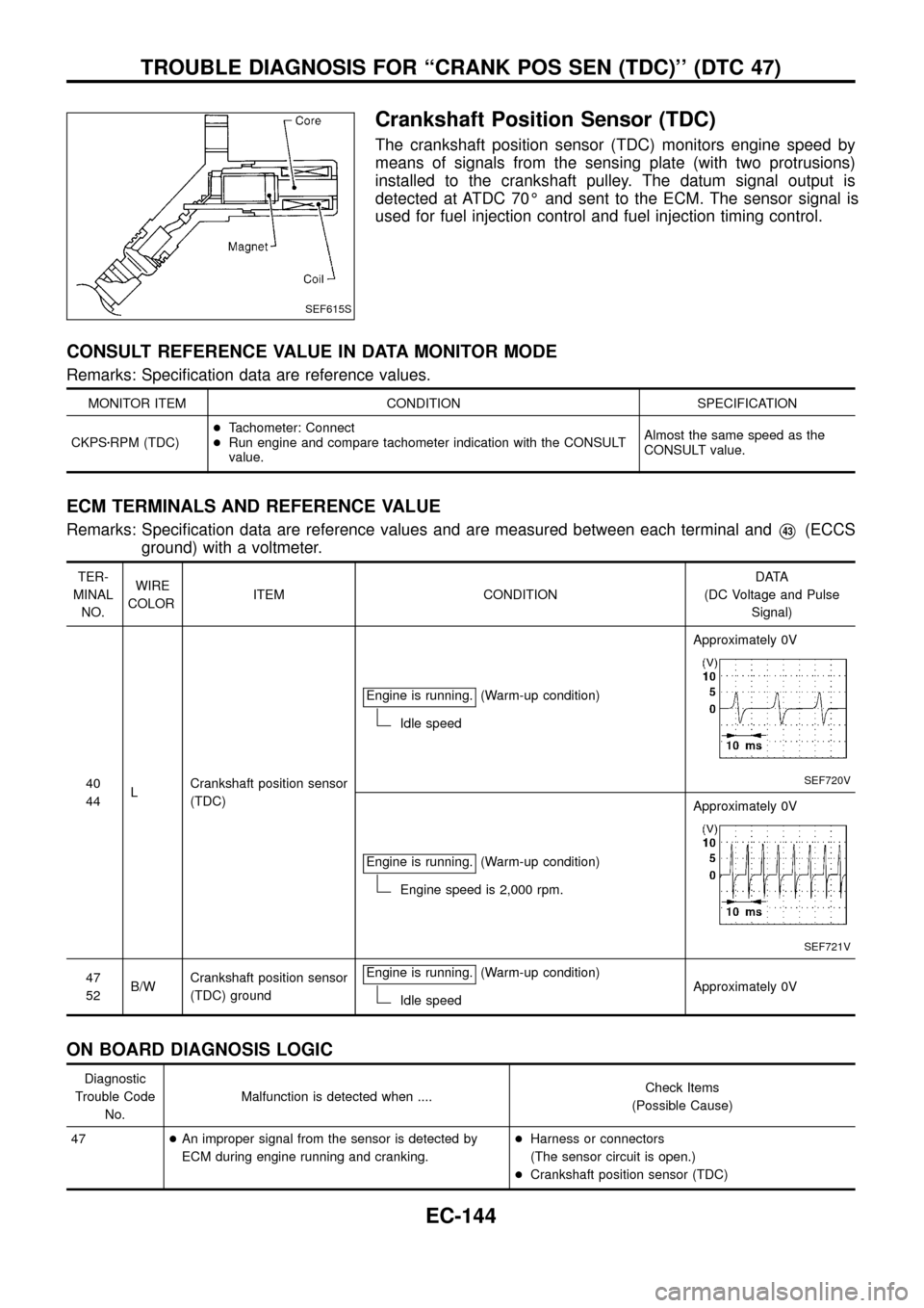
Crankshaft Position Sensor (TDC)
The crankshaft position sensor (TDC) monitors engine speed by
means of signals from the sensing plate (with two protrusions)
installed to the crankshaft pulley. The datum signal output is
detected at ATDC 70É and sent to the ECM. The sensor signal is
used for fuel injection control and fuel injection timing control.
CONSULT REFERENCE VALUE IN DATA MONITOR MODE
Remarks: Speci®cation data are reference values.
MONITOR ITEM CONDITION SPECIFICATION
CKPSzRPM (TDC)+Tachometer: Connect
+Run engine and compare tachometer indication with the CONSULT
value.Almost the same speed as the
CONSULT value.
ECM TERMINALS AND REFERENCE VALUE
Remarks: Speci®cation data are reference values and are measured between each terminal andV43(ECCS
ground) with a voltmeter.
TER-
MINAL
NO.WIRE
COLORITEM CONDITIONDATA
(DC Voltage and Pulse
Signal)
40
44LCrankshaft position sensor
(TDC)Engine is running.
(Warm-up condition)
Idle speedApproximately 0V
SEF720V
Engine is running.(Warm-up condition)
Engine speed is 2,000 rpm.Approximately 0V
SEF721V
47
52B/WCrankshaft position sensor
(TDC) groundEngine is running.(Warm-up condition)
Idle speedApproximately 0V
ON BOARD DIAGNOSIS LOGIC
Diagnostic
Trouble Code
No.Malfunction is detected when ....Check Items
(Possible Cause)
47+An improper signal from the sensor is detected by
ECM during engine running and cranking.+Harness or connectors
(The sensor circuit is open.)
+Crankshaft position sensor (TDC)
SEF615S
TROUBLE DIAGNOSIS FOR ``CRANK POS SEN (TDC)'' (DTC 47)
EC-144