1998 NISSAN PATROL battery
[x] Cancel search: batteryPage 159 of 192
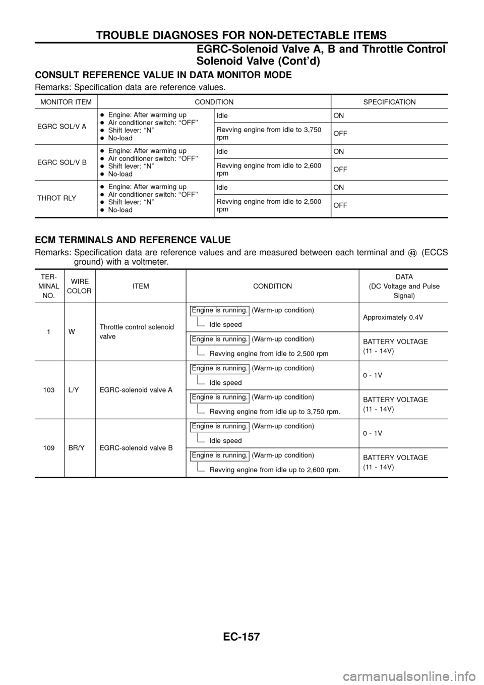
CONSULT REFERENCE VALUE IN DATA MONITOR MODE
Remarks: Speci®cation data are reference values.
MONITOR ITEM CONDITION SPECIFICATION
EGRC SOL/V A+Engine: After warming up
+Air conditioner switch: ``OFF''
+Shift lever: ``N''
+No-loadIdle ON
Revving engine from idle to 3,750
rpmOFF
EGRC SOL/V B+Engine: After warming up
+Air conditioner switch: ``OFF''
+Shift lever: ``N''
+No-loadIdle ON
Revving engine from idle to 2,600
rpmOFF
THROT RLY+Engine: After warming up
+Air conditioner switch: ``OFF''
+Shift lever: ``N''
+No-loadIdle ON
Revving engine from idle to 2,500
rpmOFF
ECM TERMINALS AND REFERENCE VALUE
Remarks: Speci®cation data are reference values and are measured between each terminal andV43(ECCS
ground) with a voltmeter.
TER-
MINAL
NO.WIRE
COLORITEM CONDITIONDATA
(DC Voltage and Pulse
Signal)
1WThrottle control solenoid
valveEngine is running.
(Warm-up condition)
Idle speedApproximately 0.4V
Engine is running.
(Warm-up condition)
Revving engine from idle to 2,500 rpmBATTERY VOLTAGE
(11 - 14V)
103 L/Y EGRC-solenoid valve AEngine is running.
(Warm-up condition)
Idle speed0-1V
Engine is running.
(Warm-up condition)
Revving engine from idle up to 3,750 rpm.BATTERY VOLTAGE
(11 - 14V)
109 BR/Y EGRC-solenoid valve BEngine is running.
(Warm-up condition)
Idle speed0-1V
Engine is running.
(Warm-up condition)
Revving engine from idle up to 2,600 rpm.BATTERY VOLTAGE
(11 - 14V)
TROUBLE DIAGNOSES FOR NON-DETECTABLE ITEMS
EGRC-Solenoid Valve A, B and Throttle Control
Solenoid Valve (Cont'd)
EC-157
Page 162 of 192
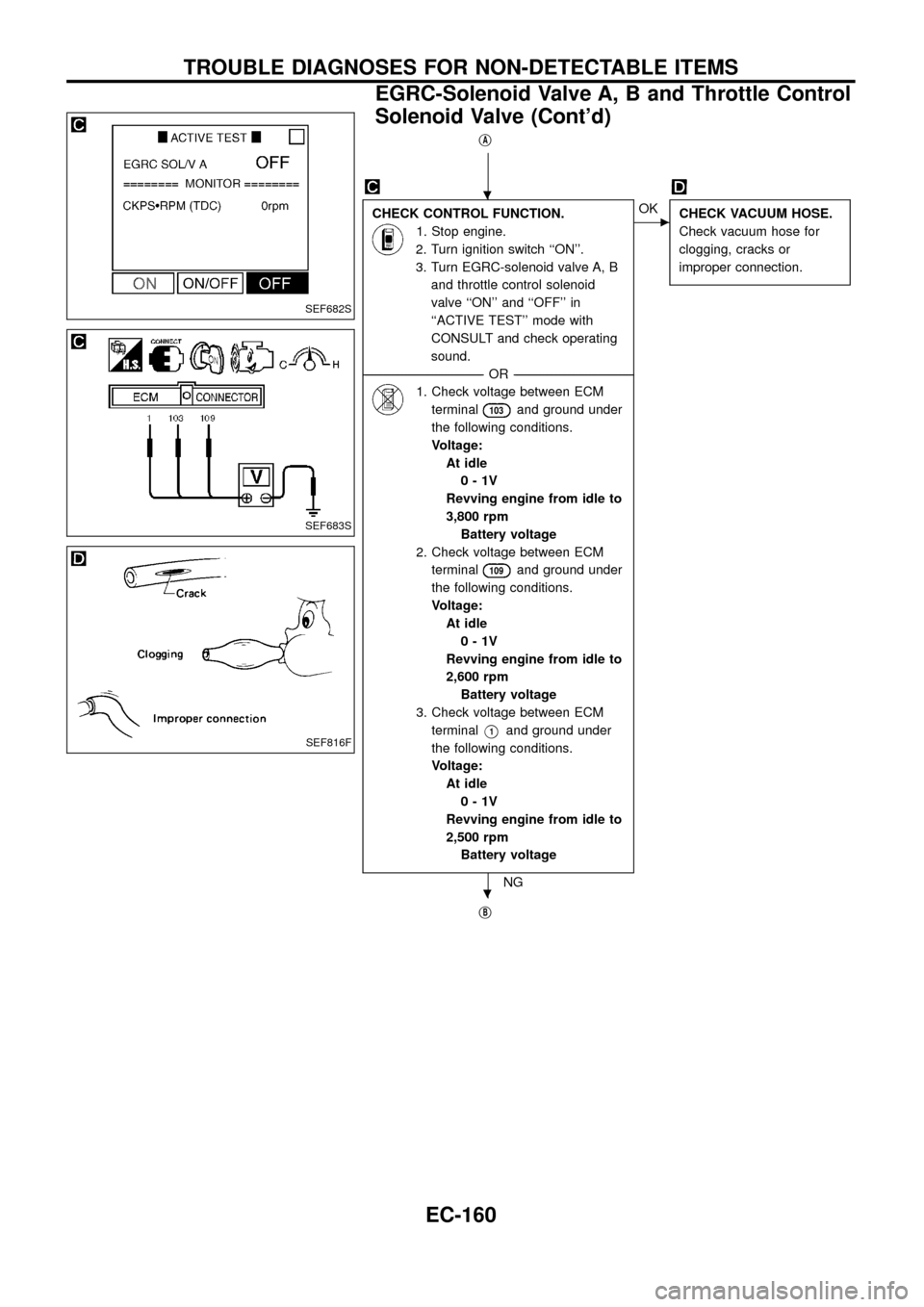
jA
CHECK CONTROL FUNCTION.
1. Stop engine.
2. Turn ignition switch ``ON''.
3. Turn EGRC-solenoid valve A, B
and throttle control solenoid
valve ``ON'' and ``OFF'' in
``ACTIVE TEST'' mode with
CONSULT and check operating
sound.
--------------------------------------------------------------------------------------------------------------------------------------OR--------------------------------------------------------------------------------------------------------------------------------------
1. Check voltage between ECM
terminal
103and ground under
the following conditions.
Voltage:
At idle
0-1V
Revving engine from idle to
3,800 rpm
Battery voltage
2. Check voltage between ECM
terminal
109and ground under
the following conditions.
Voltage:
At idle
0-1V
Revving engine from idle to
2,600 rpm
Battery voltage
3. Check voltage between ECM
terminal
V1and ground under
the following conditions.
Voltage:
At idle
0-1V
Revving engine from idle to
2,500 rpm
Battery voltage
NG
cOK
CHECK VACUUM HOSE.
Check vacuum hose for
clogging, cracks or
improper connection.
jB
SEF682S
SEF683S
SEF816F
.
.
TROUBLE DIAGNOSES FOR NON-DETECTABLE ITEMS
EGRC-Solenoid Valve A, B and Throttle Control
Solenoid Valve (Cont'd)
EC-160
Page 163 of 192
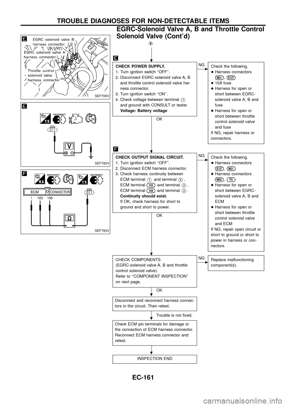
jB
CHECK POWER SUPPLY.
1. Turn ignition switch ``OFF''.
2. Disconnect EGRC-solenoid valve A, B
and throttle control solenoid valve har-
ness connector.
3. Turn ignition switch ``ON''.
4. Check voltage between terminal
V1
and ground with CONSULT or tester.
Voltage: Battery voltage
OK
cNG
Check the following.
+Harness connectors
M21,E127
+10A fuse
+Harness for open or
short between EGRC-
solenoid valve A, B and
fuse
+Harness for open or
short between throttle
control solenoid valve
and fuse
If NG, repair harness or
connectors.
CHECK OUTPUT SIGNAL CIRCUIT.
1. Turn ignition switch ``OFF''.
2. Disconnect ECM harness connector.
3. Check harness continuity between
ECM terminal
V1and terminalV2,
ECM terminal
103and terminalV2,
ECM terminal
109and terminalV2.
Continuity should exist.
If OK, check harness for short to
ground and short to power.
OK
cNG
Check the following.
+Harness connectors
E127,M21
+Harness connectors
M50,F5
+Harness for open or
short between EGRC-
solenoid valve A, B and
ECM
+Harness for open or
short between throttle
control solenoid valve
and ECM
If NG, repair open circuit or
short to ground or short to
power in harness or con-
nectors.
CHECK COMPONENTS
(EGRC-solenoid valve A, B and throttle
control solenoid valve).
Refer to ``COMPONENT INSPECTION''
on next page.
OK
cNG
Replace malfunctioning
component(s).
Disconnect and reconnect harness connec-
tors in the circuit. Then retest.
Trouble is not ®xed.
Check ECM pin terminals for damage or
the connection of ECM harness connector.
Reconnect ECM harness connector and
retest.
INSPECTION END
SEF706V
SEF782V
SEF783V
.
.
.
.
.
.
TROUBLE DIAGNOSES FOR NON-DETECTABLE ITEMS
EGRC-Solenoid Valve A, B and Throttle Control
Solenoid Valve (Cont'd)
EC-161
Page 166 of 192
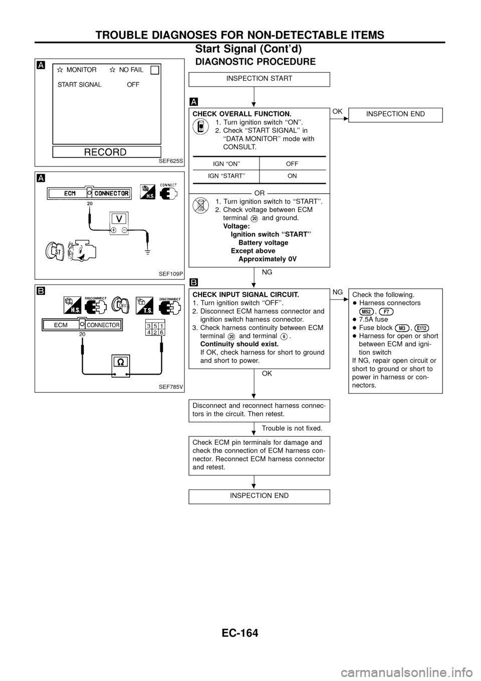
DIAGNOSTIC PROCEDURE
INSPECTION START
CHECK OVERALL FUNCTION.
1. Turn ignition switch ``ON''.
2. Check ``START SIGNAL'' in
``DATA MONITOR'' mode with
CONSULT.
--------------------------------------------------------------------------------------------------------------------------------------OR--------------------------------------------------------------------------------------------------------------------------------------
1. Turn ignition switch to ``START''.
2. Check voltage between ECM
terminal
V20and ground.
Voltage:
Ignition switch ``START''
Battery voltage
Except above
Approximately 0V
NG
cOK
INSPECTION END
CHECK INPUT SIGNAL CIRCUIT.
1. Turn ignition switch ``OFF''.
2. Disconnect ECM harness connector and
ignition switch harness connector.
3. Check harness continuity between ECM
terminal
V20and terminalV6.
Continuity should exist.
If OK, check harness for short to ground
and short to power.
OK
cNG
Check the following.
+Harness connectors
M52,F7
+7.5A fuse
+Fuse block
M3,E112
+Harness for open or short
between ECM and igni-
tion switch
If NG, repair open circuit or
short to ground or short to
power in harness or con-
nectors.
Disconnect and reconnect harness connec-
tors in the circuit. Then retest.
Trouble is not ®xed.
Check ECM pin terminals for damage and
check the connection of ECM harness con-
nector. Reconnect ECM harness connector
and retest.
INSPECTION END
IGN ``ON'' OFF
IGN ``START'' ONSEF625S
SEF109P
SEF785V
.
.
.
.
.
TROUBLE DIAGNOSES FOR NON-DETECTABLE ITEMS
Start Signal (Cont'd)
EC-164
Page 167 of 192
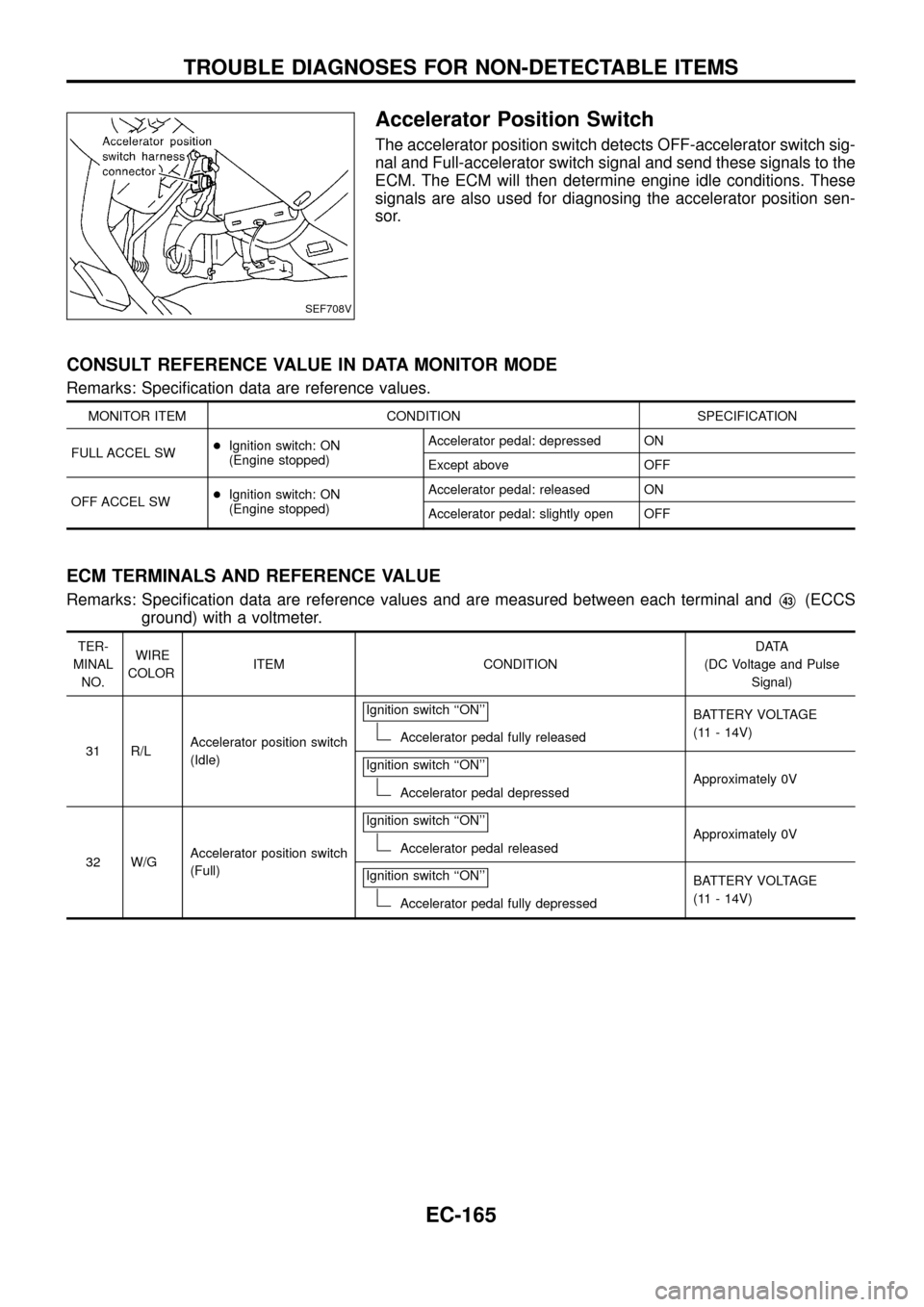
Accelerator Position Switch
The accelerator position switch detects OFF-accelerator switch sig-
nal and Full-accelerator switch signal and send these signals to the
ECM. The ECM will then determine engine idle conditions. These
signals are also used for diagnosing the accelerator position sen-
sor.
CONSULT REFERENCE VALUE IN DATA MONITOR MODE
Remarks: Speci®cation data are reference values.
MONITOR ITEM CONDITION SPECIFICATION
FULL ACCEL SW+Ignition switch: ON
(Engine stopped)Accelerator pedal: depressed ON
Except above OFF
OFF ACCEL SW+Ignition switch: ON
(Engine stopped)Accelerator pedal: released ON
Accelerator pedal: slightly open OFF
ECM TERMINALS AND REFERENCE VALUE
Remarks: Speci®cation data are reference values and are measured between each terminal andV43(ECCS
ground) with a voltmeter.
TER-
MINAL
NO.WIRE
COLORITEM CONDITIONDATA
(DC Voltage and Pulse
Signal)
31 R/LAccelerator position switch
(Idle)Ignition switch ``ON''
Accelerator pedal fully releasedBATTERY VOLTAGE
(11 - 14V)
Ignition switch ``ON''
Accelerator pedal depressedApproximately 0V
32 W/GAccelerator position switch
(Full)Ignition switch ``ON''
Accelerator pedal releasedApproximately 0V
Ignition switch ``ON''
Accelerator pedal fully depressedBATTERY VOLTAGE
(11 - 14V)
SEF708V
TROUBLE DIAGNOSES FOR NON-DETECTABLE ITEMS
EC-165
Page 169 of 192
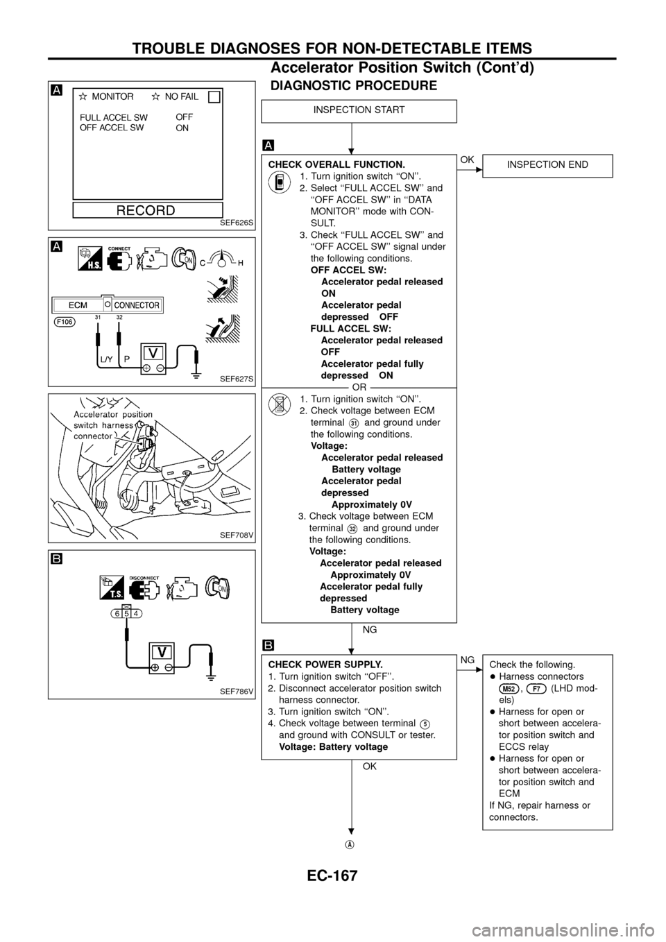
DIAGNOSTIC PROCEDURE
INSPECTION START
CHECK OVERALL FUNCTION.
1. Turn ignition switch ``ON''.
2. Select ``FULL ACCEL SW'' and
``OFF ACCEL SW'' in ``DATA
MONITOR'' mode with CON-
SULT.
3. Check ``FULL ACCEL SW'' and
``OFF ACCEL SW'' signal under
the following conditions.
OFF ACCEL SW:
Accelerator pedal released
ON
Accelerator pedal
depressed OFF
FULL ACCEL SW:
Accelerator pedal released
OFF
Accelerator pedal fully
depressed ON
--------------------------------------------------------------------------------------------------------------------------------------OR--------------------------------------------------------------------------------------------------------------------------------------
1. Turn ignition switch ``ON''.
2. Check voltage between ECM
terminal
V31and ground under
the following conditions.
Voltage:
Accelerator pedal released
Battery voltage
Accelerator pedal
depressed
Approximately 0V
3. Check voltage between ECM
terminal
V32and ground under
the following conditions.
Voltage:
Accelerator pedal released
Approximately 0V
Accelerator pedal fully
depressed
Battery voltage
NG
cOK
INSPECTION END
CHECK POWER SUPPLY.
1. Turn ignition switch ``OFF''.
2. Disconnect accelerator position switch
harness connector.
3. Turn ignition switch ``ON''.
4. Check voltage between terminal
V5
and ground with CONSULT or tester.
Voltage: Battery voltage
OK
cNG
Check the following.
+Harness connectors
M52,F7(LHD mod-
els)
+Harness for open or
short between accelera-
tor position switch and
ECCS relay
+Harness for open or
short between accelera-
tor position switch and
ECM
If NG, repair harness or
connectors.
jA
SEF626S
SEF627S
SEF708V
SEF786V
.
.
.
TROUBLE DIAGNOSES FOR NON-DETECTABLE ITEMS
Accelerator Position Switch (Cont'd)
EC-167
Page 173 of 192
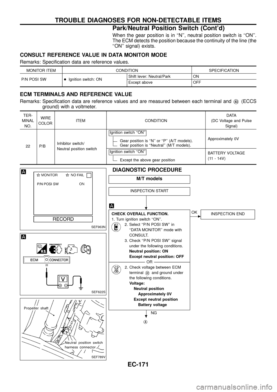
When the gear position is in ``N'', neutral position switch is ``ON''.
The ECM detects the position because the continuity of the line (the
``ON'' signal) exists.
CONSULT REFERENCE VALUE IN DATA MONITOR MODE
Remarks: Speci®cation data are reference values.
MONITOR ITEM CONDITION SPECIFICATION
P/N POSI SW+Ignition switch: ONShift lever: Neutral/Park ON
Except above OFF
ECM TERMINALS AND REFERENCE VALUE
Remarks: Speci®cation data are reference values and are measured between each terminal andV43(ECCS
ground) with a voltmeter.
TER-
MINAL
NO.WIRE
COLORITEM CONDITIONDATA
(DC Voltage and Pulse
Signal)
22 P/BInhibitor switch/
Neutral position switchIgnition switch ``ON''
Gear position is ``N'' or ``P'' (A/T models).Gear position is ``Neutral'' (M/T models).Approximately 0V
Ignition switch ``ON''
Except the above gear positionBATTERY VOLTAGE
(11 - 14V)
DIAGNOSTIC PROCEDURE
M/T models
INSPECTION START
CHECK OVERALL FUNCTION.
1. Turn ignition switch ``ON''.
2. Select ``P/N POSI SW'' in
``DATA MONITOR'' mode with
CONSULT.
3. Check ``P/N POSI SW'' signal
under the following conditions.
Neutral position: ON
Except neutral position: OFF
--------------------------------------------------------------------------------------------------------------------------------------OR--------------------------------------------------------------------------------------------------------------------------------------
2. Check voltage between ECM
terminal
V22and ground under
the following conditions.
Voltage:
Neutral position
Approximately 0V
Except neutral position
Battery voltage
NG
cOK
INSPECTION END
jA
SEF963N
SEF622S
SEF789V
.
.
TROUBLE DIAGNOSES FOR NON-DETECTABLE ITEMS
Park/Neutral Position Switch (Cont'd)
EC-171
Page 175 of 192
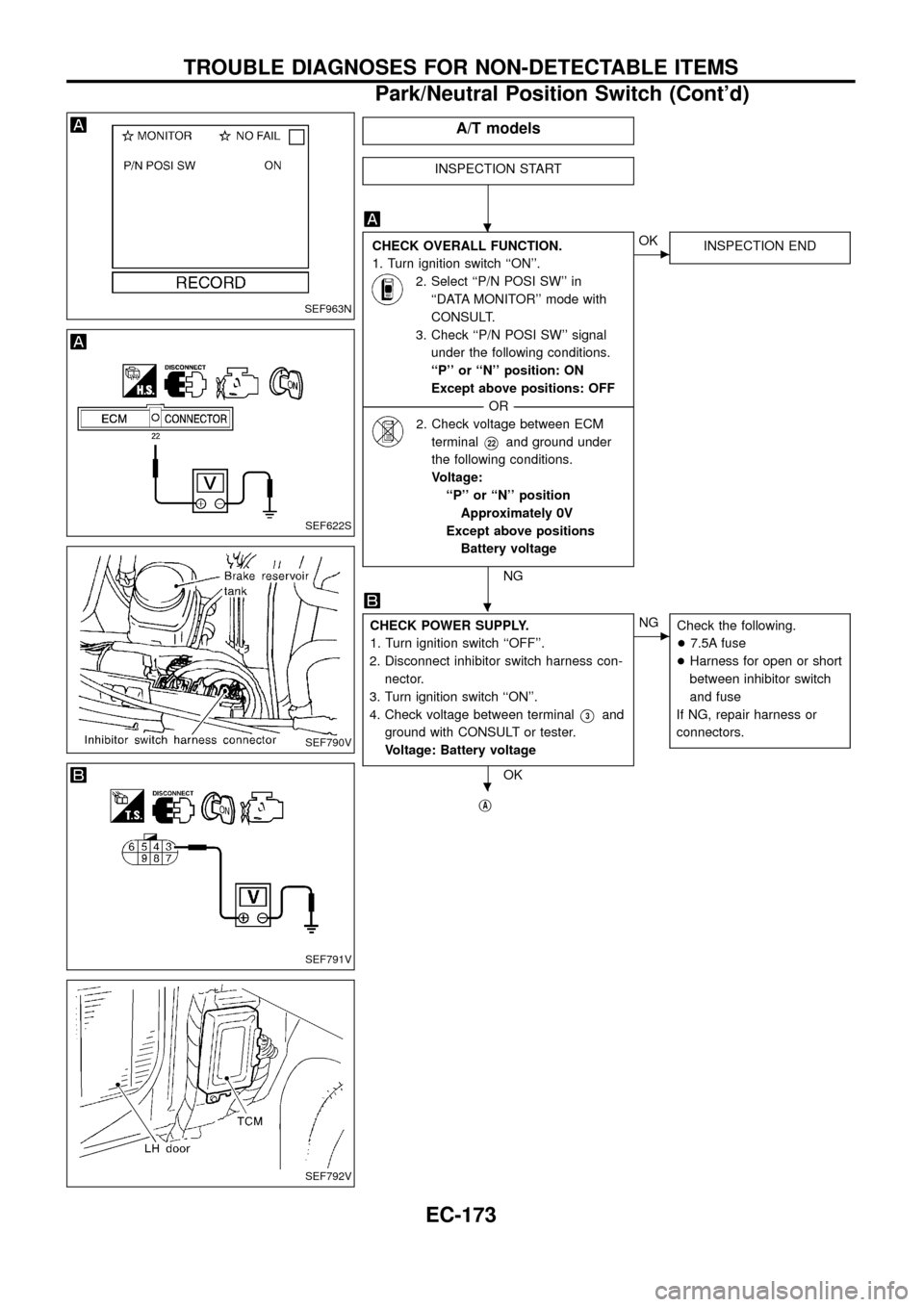
A/T models
INSPECTION START
CHECK OVERALL FUNCTION.
1. Turn ignition switch ``ON''.
2. Select ``P/N POSI SW'' in
``DATA MONITOR'' mode with
CONSULT.
3. Check ``P/N POSI SW'' signal
under the following conditions.
``P'' or ``N'' position: ON
Except above positions: OFF
--------------------------------------------------------------------------------------------------------------------------------------OR--------------------------------------------------------------------------------------------------------------------------------------
2. Check voltage between ECM
terminal
V22and ground under
the following conditions.
Voltage:
``P'' or ``N'' position
Approximately 0V
Except above positions
Battery voltage
NG
cOK
INSPECTION END
CHECK POWER SUPPLY.
1. Turn ignition switch ``OFF''.
2. Disconnect inhibitor switch harness con-
nector.
3. Turn ignition switch ``ON''.
4. Check voltage between terminal
V3and
ground with CONSULT or tester.
Voltage: Battery voltage
OK
cNG
Check the following.
+7.5A fuse
+Harness for open or short
between inhibitor switch
and fuse
If NG, repair harness or
connectors.
jA
SEF963N
SEF622S
SEF790V
SEF791V
SEF792V
.
.
.
TROUBLE DIAGNOSES FOR NON-DETECTABLE ITEMS
Park/Neutral Position Switch (Cont'd)
EC-173