Page 52 of 192

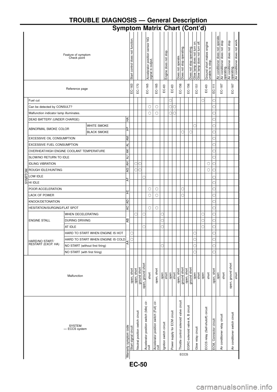
SYSTEM
Ð ECCS systemMalfunction
SYMPTOM
Reference page Feature of symptom
Check point
HARD/NO START/
RESTART (EXCP. HA) ENGINE STALL HESITATION/SURGING/FLAT SPOT KNOCK/DETONATION
LACK OF POWER
POOR ACCELERATION
HI IDLE
LOW IDLE
ROUGH IDLE/HUNTING
IDLING VIBRATION
SLOW/NO RETURN TO IDLE
OVERHEAT/HIGH ENGINE COOLANT TEMPERATURE
EXCESSIVE FUEL CONSUMPTION
EXCESSIVE OIL CONSUMPTION ABNORMAL SMOKE COLOR
DEAD BATTERY (UNDER CHARGE) Malfunction indicator lamp illuminates.
Can be detected by CONSULT?
Fuel cut
NO START (with ®rst ®ring) NO START (without ®rst ®ring)
HARD TO START WHEN ENGINE IS COLD
HARD TO START WHEN ENGINE IS HOT
AT IDLE
DURING DRIVING
WHEN DECELERATINGBLACK SMOKE WHITE SMOKE
Warranty symptom code AA AB AC AD AE AF AG AH AJ AK AL AM AP HAECCS
Start signal circuit open, shortjjEC-163 Start control does not function.
Neutral position switch circuitopen, shortjjj
EC-170
ground shortjj
Accelerator position switch (Idle) cir-
cuitopen, ground shortjj j
EC-165
shortjjj jjAccelerator position sensor NG
signal is output.
Accelerator position switch (Full) cir-
cuitopen, shortjjj jjEC-165
Ignition switch circuitopenj jjj
EC-63
shortEngine does not stop.
Power supply for ECM circuitopenjjj
EC-63
shortjj
Throttle control solenoid valve circuitopen, short
EC-156Does not operate.
ground shortjj jDoes not stop operating.
EGRC-solenoid valve A, B circuitopen, short
EC-156
ground shortjDoes not stop operating.
Glow relay circuitopenjjjjj
EC-151Glow lamp does not turn on.
shortGlow lamp does not turn off.
ECCS relay (Self-shutoff) circuitopenjjjj
EC-63
shortjjGround short makes engine
unable to stop.
ECM, Connector circuit open, shortjjjjjjjjjjjjj jjjjjjjjjjjjEC-111
Air conditioner relay circuitopen
EC-187Air conditioner does not operate.
shortAir conditioner does not stop
operating.
Air conditioner switch circuitopen, ground short
EC-187Air conditioner does not stop
operating.
shortAir conditioner does not work.
TROUBLE DIAGNOSIS Ð General Description
Symptom Matrix Chart (Cont'd)
EC-50
Page 98 of 192

Electric Governor
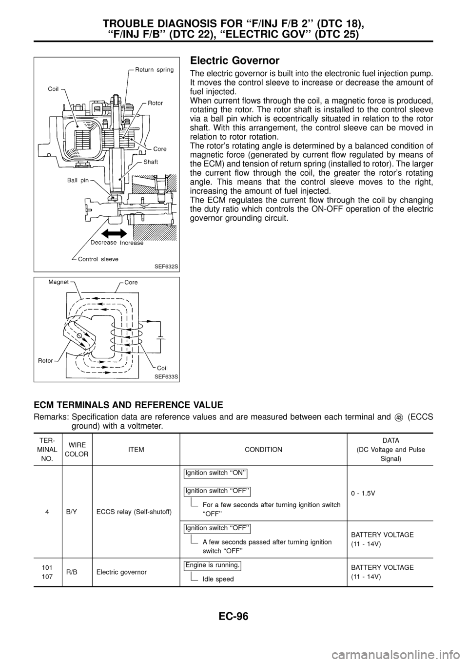
The electric governor is built into the electronic fuel injection pump.
It moves the control sleeve to increase or decrease the amount of
fuel injected.
When current ¯ows through the coil, a magnetic force is produced,
rotating the rotor. The rotor shaft is installed to the control sleeve
via a ball pin which is eccentrically situated in relation to the rotor
shaft. With this arrangement, the control sleeve can be moved in
relation to rotor rotation.
The rotor's rotating angle is determined by a balanced condition of
magnetic force (generated by current ¯ow regulated by means of
the ECM) and tension of return spring (installed to rotor). The larger
the current ¯ow through the coil, the greater the rotor's rotating
angle. This means that the control sleeve moves to the right,
increasing the amount of fuel injected.
The ECM regulates the current ¯ow through the coil by changing
the duty ratio which controls the ON-OFF operation of the electric
governor grounding circuit.
ECM TERMINALS AND REFERENCE VALUE
Remarks: Speci®cation data are reference values and are measured between each terminal andV43(ECCS
ground) with a voltmeter.
TER-
MINAL
NO.WIRE
COLORITEM CONDITIONDATA
(DC Voltage and Pulse
Signal)
4 B/Y ECCS relay (Self-shutoff)Ignition switch ``ON''
Ignition switch ``OFF''
For a few seconds after turning ignition switch
``OFF''0 - 1.5V
Ignition switch ``OFF''
A few seconds passed after turning ignition
switch ``OFF''BATTERY VOLTAGE
(11 - 14V)
101
107R/B Electric governorEngine is running.
Idle speedBATTERY VOLTAGE
(11 - 14V)
SEF632S
SEF633S
TROUBLE DIAGNOSIS FOR ``F/INJ F/B 2'' (DTC 18),
``F/INJ F/B'' (DTC 22), ``ELECTRIC GOV'' (DTC 25)
EC-96
Page 132 of 192

Fuel Cut Solenoid Valve
When the ignition switch is OFF, the ECM turns the fuel cut sole-
noid valve OFF (under this condition, no current ¯ows through the
fuel cut solenoid valve), shutting off fuel supply.
When the engine is not operating due to trouble, the fuel cut sole-
noid valve may or may not be OFF even when the ignition switch
is ON.
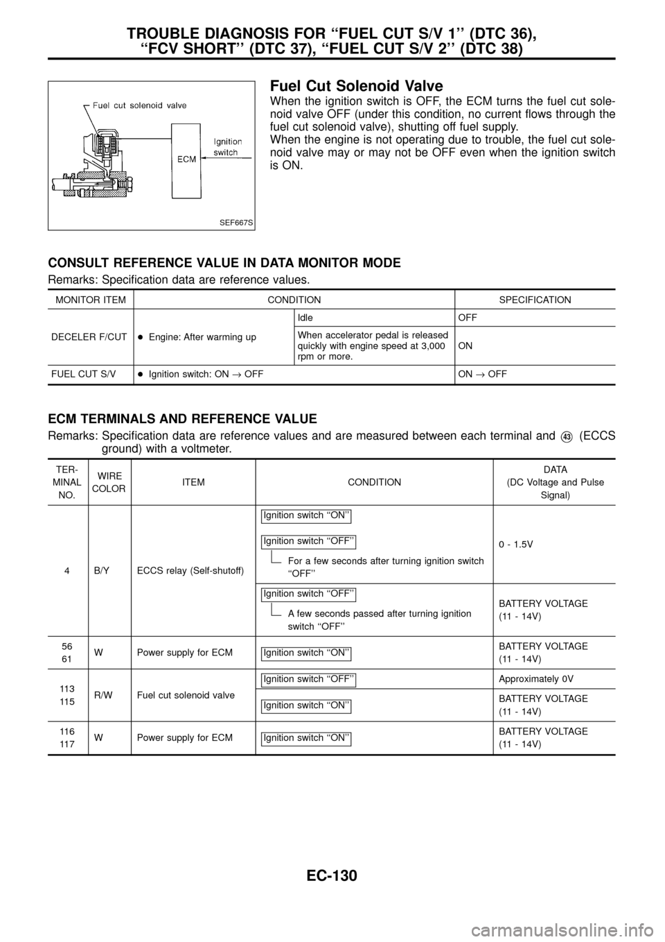
CONSULT REFERENCE VALUE IN DATA MONITOR MODE
Remarks: Speci®cation data are reference values.
MONITOR ITEM CONDITION SPECIFICATION
DECELER F/CUT+Engine: After warming upIdle OFF
When accelerator pedal is released
quickly with engine speed at 3,000
rpm or more.ON
FUEL CUT S/V+Ignition switch: ON®OFF ON®OFF
ECM TERMINALS AND REFERENCE VALUE
Remarks: Speci®cation data are reference values and are measured between each terminal andV43(ECCS
ground) with a voltmeter.
TER-
MINAL
NO.WIRE
COLORITEM CONDITIONDATA
(DC Voltage and Pulse
Signal)
4 B/Y ECCS relay (Self-shutoff)Ignition switch ``ON''
Ignition switch ``OFF''
For a few seconds after turning ignition switch
``OFF''0 - 1.5V
Ignition switch ``OFF''
A few seconds passed after turning ignition
switch ``OFF''BATTERY VOLTAGE
(11 - 14V)
56
61W Power supply for ECM Ignition switch ``ON''
BATTERY VOLTAGE
(11 - 14V)
11 3
11 5R/W Fuel cut solenoid valveIgnition switch ``OFF''
Approximately 0V
Ignition switch ``ON''
BATTERY VOLTAGE
(11 - 14V)
11 6
11 7W Power supply for ECM Ignition switch ``ON''
BATTERY VOLTAGE
(11 - 14V)
SEF667S
TROUBLE DIAGNOSIS FOR ``FUEL CUT S/V 1'' (DTC 36),
``FCV SHORT'' (DTC 37), ``FUEL CUT S/V 2'' (DTC 38)
EC-130