1998 NISSAN PATROL Stop lamp
[x] Cancel search: Stop lampPage 2 of 326
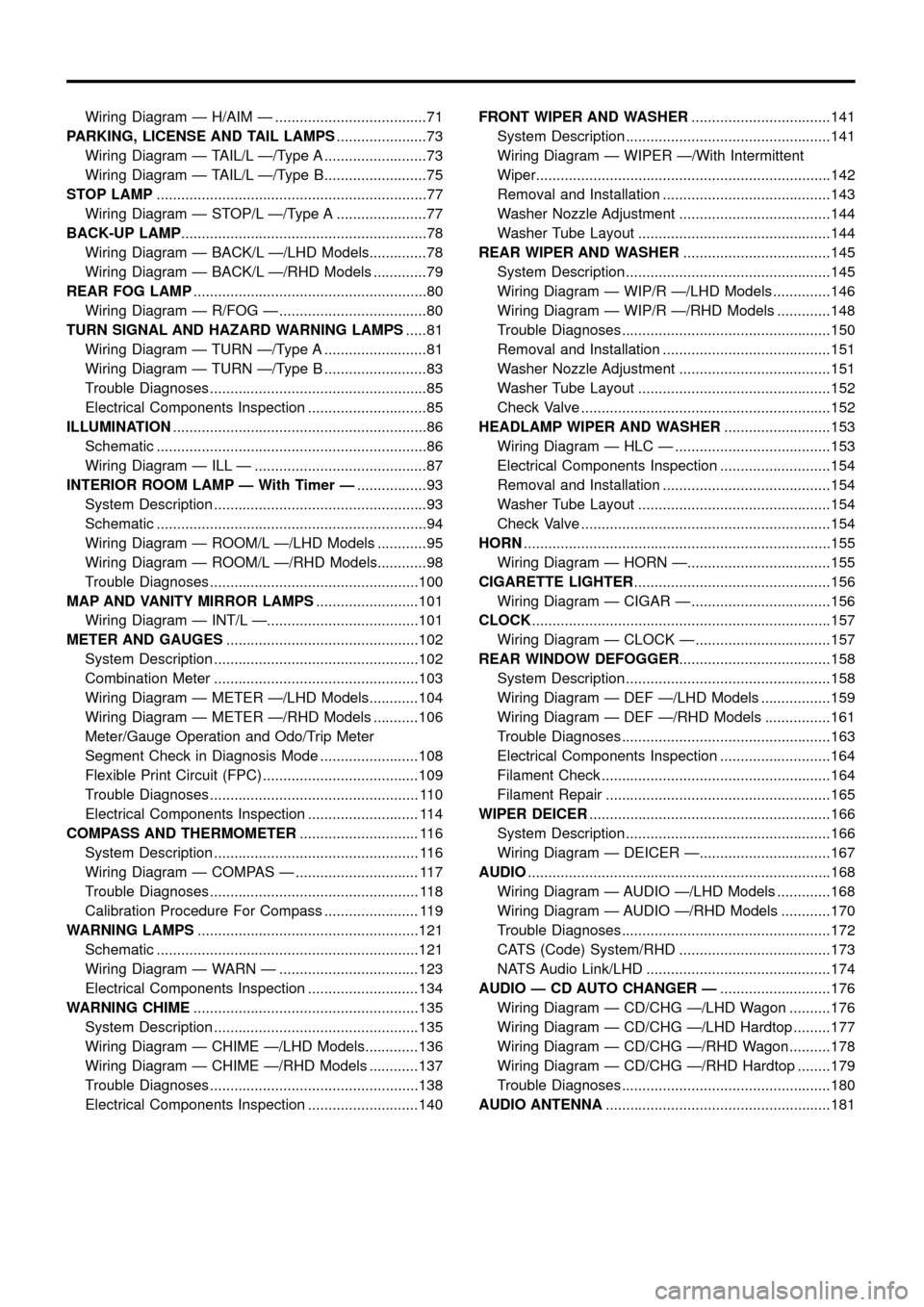
Wiring Diagram Ð H/AIM Ð .....................................71
PARKING, LICENSE AND TAIL LAMPS......................73
Wiring Diagram Ð TAIL/L Ð/Type A .........................73
Wiring Diagram Ð TAIL/L Ð/Type B.........................75
STOP LAMP..................................................................77
Wiring Diagram Ð STOP/L Ð/Type A ......................77
BACK-UP LAMP............................................................78
Wiring Diagram Ð BACK/L Ð/LHD Models..............78
Wiring Diagram Ð BACK/L Ð/RHD Models .............79
REAR FOG LAMP.........................................................80
Wiring Diagram Ð R/FOG Ð ....................................80
TURN SIGNAL AND HAZARD WARNING LAMPS.....81
Wiring Diagram Ð TURN Ð/Type A .........................81
Wiring Diagram Ð TURN Ð/Type B .........................83
Trouble Diagnoses.....................................................85
Electrical Components Inspection .............................85
ILLUMINATION..............................................................86
Schematic ..................................................................86
Wiring Diagram Ð ILL Ð ..........................................87
INTERIOR ROOM LAMP Ð With Timer Ð.................93
System Description ....................................................93
Schematic ..................................................................94
Wiring Diagram Ð ROOM/L Ð/LHD Models ............95
Wiring Diagram Ð ROOM/L Ð/RHD Models............98
Trouble Diagnoses...................................................100
MAP AND VANITY MIRROR LAMPS.........................101
Wiring Diagram Ð INT/L Ð.....................................101
METER AND GAUGES...............................................102
System Description ..................................................102
Combination Meter ..................................................103
Wiring Diagram Ð METER Ð/LHD Models............104
Wiring Diagram Ð METER Ð/RHD Models ...........106
Meter/Gauge Operation and Odo/Trip Meter
Segment Check in Diagnosis Mode ........................108
Flexible Print Circuit (FPC) ......................................109
Trouble Diagnoses................................................... 110
Electrical Components Inspection ........................... 114
COMPASS AND THERMOMETER............................. 116
System Description .................................................. 116
Wiring Diagram Ð COMPAS Ð .............................. 117
Trouble Diagnoses................................................... 118
Calibration Procedure For Compass ....................... 119
WARNING LAMPS......................................................121
Schematic ................................................................121
Wiring Diagram Ð WARN Ð ..................................123
Electrical Components Inspection ...........................134
WARNING CHIME.......................................................135
System Description ..................................................135
Wiring Diagram Ð CHIME Ð/LHD Models.............136
Wiring Diagram Ð CHIME Ð/RHD Models ............137
Trouble Diagnoses...................................................138
Electrical Components Inspection ...........................140FRONT WIPER AND WASHER..................................141
System Description ..................................................141
Wiring Diagram Ð WIPER Ð/With Intermittent
Wiper........................................................................142
Removal and Installation .........................................143
Washer Nozzle Adjustment .....................................144
Washer Tube Layout ...............................................144
REAR WIPER AND WASHER....................................145
System Description ..................................................145
Wiring Diagram Ð WIP/R Ð/LHD Models ..............146
Wiring Diagram Ð WIP/R Ð/RHD Models .............148
Trouble Diagnoses...................................................150
Removal and Installation .........................................151
Washer Nozzle Adjustment .....................................151
Washer Tube Layout ...............................................152
Check Valve .............................................................152
HEADLAMP WIPER AND WASHER..........................153
Wiring Diagram Ð HLC Ð ......................................153
Electrical Components Inspection ...........................154
Removal and Installation .........................................154
Washer Tube Layout ...............................................154
Check Valve .............................................................154
HORN...........................................................................155
Wiring Diagram Ð HORN Ð...................................155
CIGARETTE LIGHTER................................................156
Wiring Diagram Ð CIGAR Ð ..................................156
CLOCK.........................................................................157
Wiring Diagram Ð CLOCK Ð .................................157
REAR WINDOW DEFOGGER.....................................158
System Description ..................................................158
Wiring Diagram Ð DEF Ð/LHD Models .................159
Wiring Diagram Ð DEF Ð/RHD Models ................161
Trouble Diagnoses...................................................163
Electrical Components Inspection ...........................164
Filament Check ........................................................164
Filament Repair .......................................................165
WIPER DEICER...........................................................166
System Description ..................................................166
Wiring Diagram Ð DEICER Ð................................167
AUDIO..........................................................................168
Wiring Diagram Ð AUDIO Ð/LHD Models .............168
Wiring Diagram Ð AUDIO Ð/RHD Models ............170
Trouble Diagnoses...................................................172
CATS (Code) System/RHD .....................................173
NATS Audio Link/LHD .............................................174
AUDIO Ð CD AUTO CHANGER Ð...........................176
Wiring Diagram Ð CD/CHG Ð/LHD Wagon ..........176
Wiring Diagram Ð CD/CHG Ð/LHD Hardtop .........177
Wiring Diagram Ð CD/CHG Ð/RHD Wagon ..........178
Wiring Diagram Ð CD/CHG Ð/RHD Hardtop ........179
Trouble Diagnoses...................................................180
AUDIO ANTENNA.......................................................181
Page 69 of 326
System Description
OPERATION
Headlamp system on vehicles for North Europe contains a daytime light system. The unit operates to illumi-
nate headlamps low beam, parking, tail, license lamps and illuminations automatically in the following condi-
tions.
+The engine is running with lighting switch in OFF position.
When the any of following conditions exists, the daytime light operation will be canceled.
+Ignition switch is in any position other than ON
+Engine is stopped
+Lighting switch is turned to 1st or 2nd position.
If the daytime light system is canceled, lighting switch operations are the same as for conventional light sys-
tem.
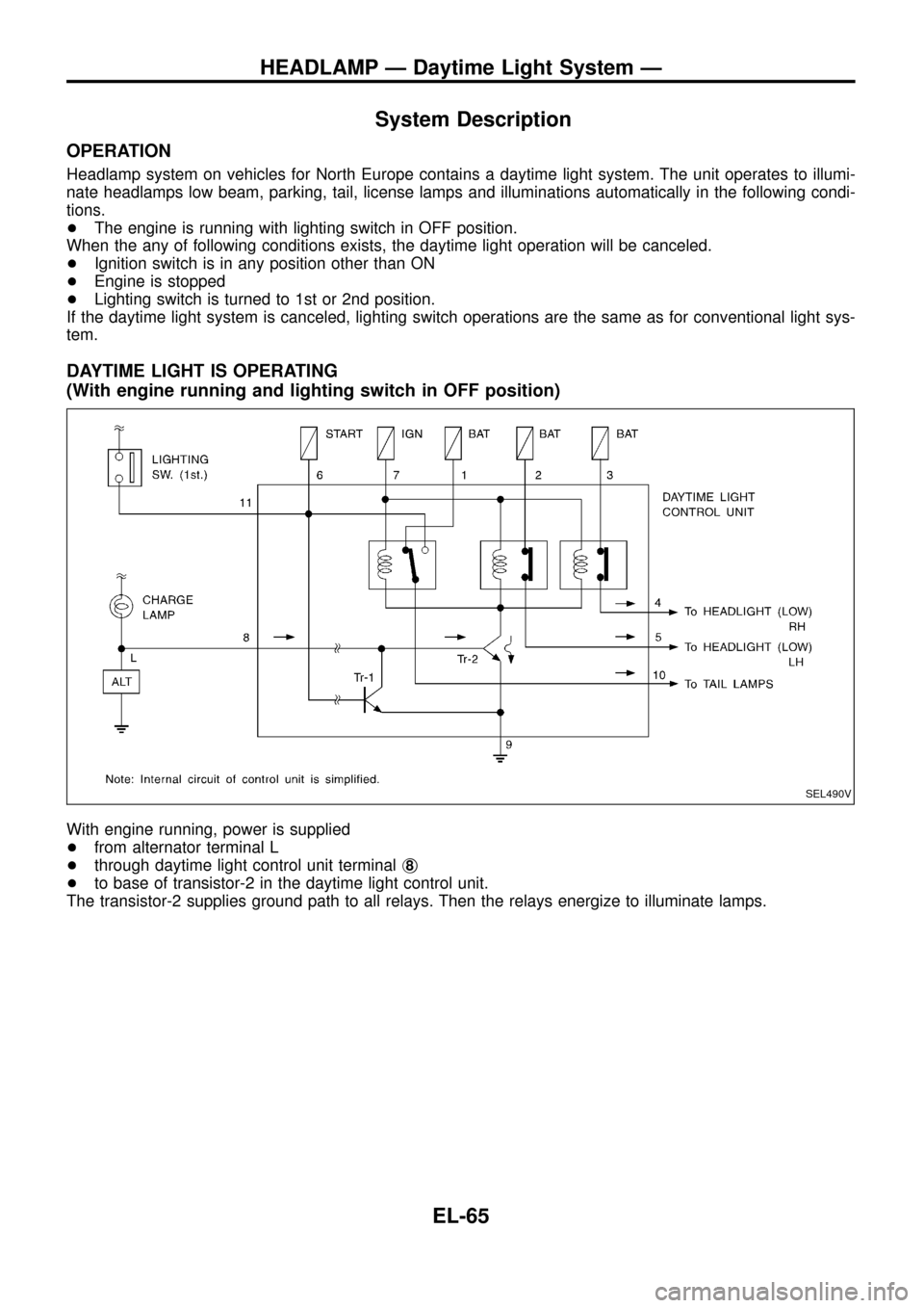
DAYTIME LIGHT IS OPERATING
(With engine running and lighting switch in OFF position)
With engine running, power is supplied
+from alternator terminal L
+through daytime light control unit terminalj
8
+to base of transistor-2 in the daytime light control unit.
The transistor-2 supplies ground path to all relays. Then the relays energize to illuminate lamps.
SEL490V
HEADLAMP Ð Daytime Light System Ð
EL-65
Page 73 of 326
Trouble Diagnoses
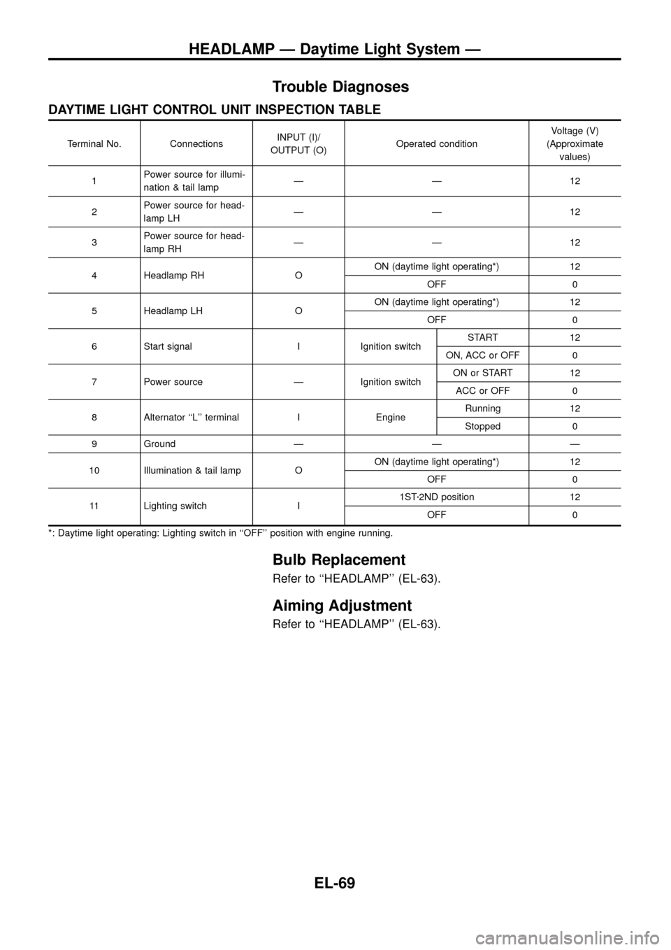
DAYTIME LIGHT CONTROL UNIT INSPECTION TABLE
Terminal No. ConnectionsINPUT (I)/
OUTPUT (O)Operated conditionVoltage (V)
(Approximate
values)
1Power source for illumi-
nation & tail lampÐÐ12
2Power source for head-
lamp LHÐÐ12
3Power source for head-
lamp RHÐÐ12
4 Headlamp RH OON (daytime light operating*) 12
OFF 0
5 Headlamp LH OON (daytime light operating*) 12
OFF 0
6 Start signal I Ignition switchSTART 12
ON, ACC or OFF 0
7 Power source Ð Ignition switchON or START 12
ACC or OFF 0
8 Alternator ``L'' terminal I EngineRunning 12
Stopped 0
9 Ground Ð Ð Ð
10 Illumination & tail lamp OON (daytime light operating*) 12
OFF 0
11 Lighting switch I1STz2ND position 12
OFF 0
*: Daytime light operating: Lighting switch in ``OFF'' position with engine running.
Bulb Replacement
Refer to ``HEADLAMP'' (EL-63).
Aiming Adjustment
Refer to ``HEADLAMP'' (EL-63).
HEADLAMP Ð Daytime Light System Ð
EL-69
Page 74 of 326
![NISSAN PATROL 1998 Y61 / 5.G Electrical System Workshop Manual System Description
CIRCUIT OPERATION
[Example]
Aiming switch ``0
+When the aiming switch is set to ``0, the motor will not start.
This is because the power terminals are positioned at the non-
con NISSAN PATROL 1998 Y61 / 5.G Electrical System Workshop Manual System Description
CIRCUIT OPERATION
[Example]
Aiming switch ``0
+When the aiming switch is set to ``0, the motor will not start.
This is because the power terminals are positioned at the non-
con](/manual-img/5/616/w960_616-73.png)
System Description
CIRCUIT OPERATION
[Example]
Aiming switch ``0''
+When the aiming switch is set to ``0'', the motor will not start.
This is because the power terminals are positioned at the non-
conductive section of the sensor's rotary unit.
Aiming switch ``0''®``1''
+When the aiming switch is moved from ``0'' to ``1'', the sensor's
conductive section activates the relay. Power is supplied
through the relay to the motor. The headlamps will then move
in the ``DOWN'' direction.
+The motor continues to rotate while the rotary unit of the sen-
sor moves from point A to point B.
+The power terminals will then be positioned at the nonconduc-
tive section, disconnecting the power to the motor. The motor
will then stop.
Aiming switch ``1''®``0''
+When the aiming switch is moved from ``1'' to ``0'', the sensor's
conductive section activates the relay. Power is supplied
through the relay to the motor. The motor will rotate to move the
headlamps in the ``UP'' direction.
+When the rotary unit of the sensor moves from point B to point
A, the motor will stop.
SEL465M
SEL364P
SEL365P
HEADLAMP Ð Headlamp Aiming Control Ð
EL-70
Page 81 of 326
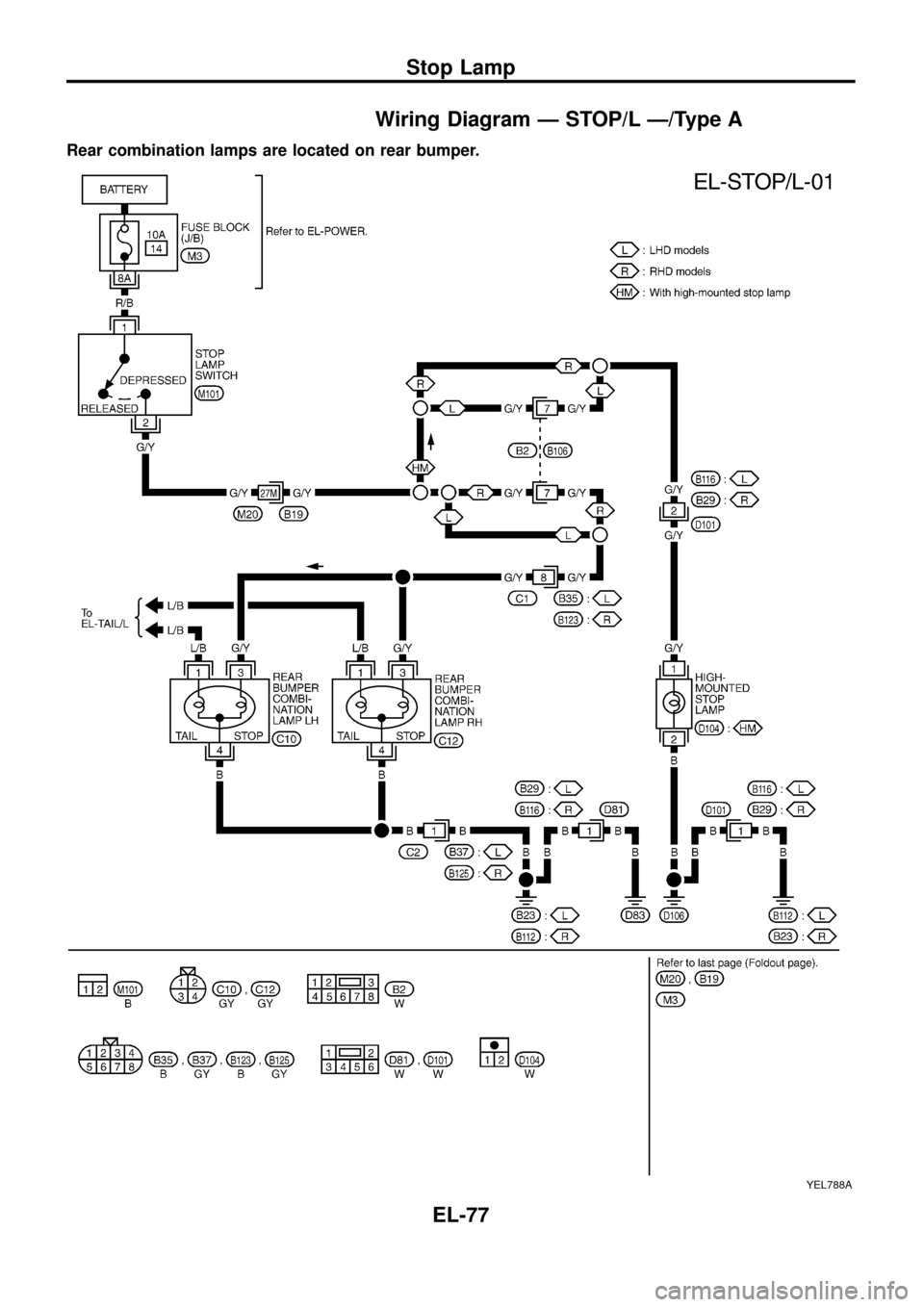
Wiring Diagram Ð STOP/L Ð/Type A
Rear combination lamps are located on rear bumper.
YEL788A
Stop Lamp
EL-77
Page 138 of 326
Electrical Components Inspection
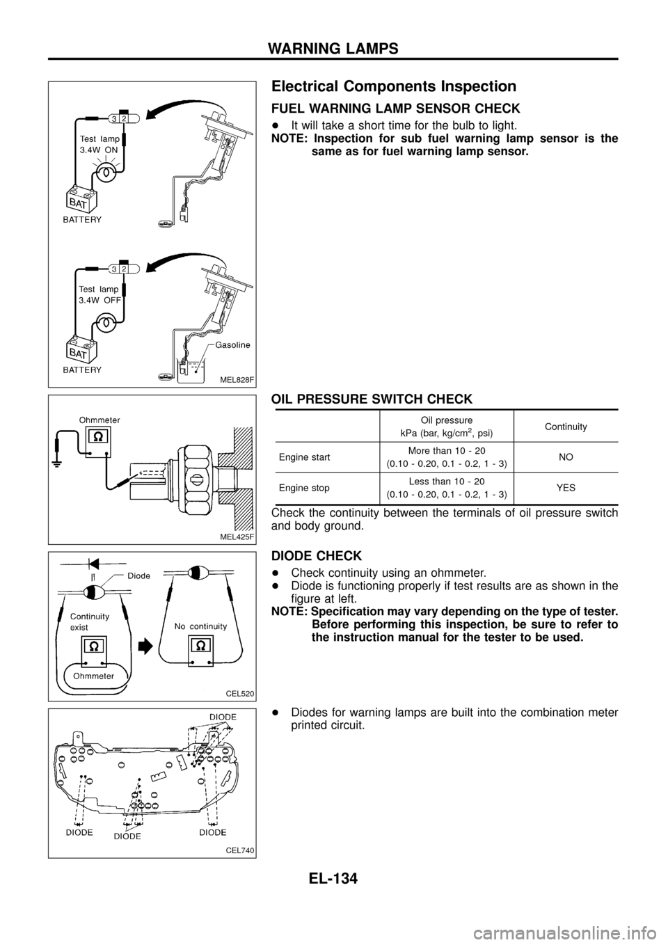
FUEL WARNING LAMP SENSOR CHECK
+It will take a short time for the bulb to light.
NOTE: Inspection for sub fuel warning lamp sensor is the
same as for fuel warning lamp sensor.
OIL PRESSURE SWITCH CHECK
Oil pressure
kPa (bar, kg/cm2, psi)Continuity
Engine startMore than 10 - 20
(0.10 - 0.20, 0.1 - 0.2,1-3)NO
Engine stopLess than 10 - 20
(0.10 - 0.20, 0.1 - 0.2,1-3)YES
Check the continuity between the terminals of oil pressure switch
and body ground.
DIODE CHECK
+Check continuity using an ohmmeter.
+Diode is functioning properly if test results are as shown in the
®gure at left.
NOTE: Speci®cation may vary depending on the type of tester.
Before performing this inspection, be sure to refer to
the instruction manual for the tester to be used.
+Diodes for warning lamps are built into the combination meter
printed circuit.
MEL828F
MEL425F
CEL520
CEL740
WARNING LAMPS
EL-134
Page 158 of 326
Electrical Components Inspection
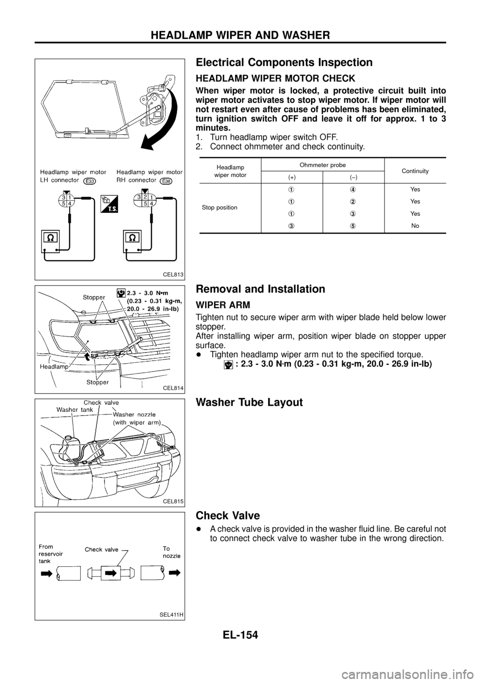
HEADLAMP WIPER MOTOR CHECK
When wiper motor is locked, a protective circuit built into
wiper motor activates to stop wiper motor. If wiper motor will
not restart even after cause of problems has been eliminated,
turn ignition switch OFF and leave it off for approx. 1 to 3
minutes.
1. Turn headlamp wiper switch OFF.
2. Connect ohmmeter and check continuity.
Headlamp
wiper motorOhmmeter probe
Continuity
(+) (þ)
Stop positionj
1j4Ye s
j
1j2Ye s
j
1j3Ye s
j
3j5No
Removal and Installation
WIPER ARM
Tighten nut to secure wiper arm with wiper blade held below lower
stopper.
After installing wiper arm, position wiper blade on stopper upper
surface.
+Tighten headlamp wiper arm nut to the speci®ed torque.
: 2.3 - 3.0 Nzm (0.23 - 0.31 kg-m, 20.0 - 26.9 in-lb)
Washer Tube Layout
Check Valve
+A check valve is provided in the washer ¯uid line. Be careful not
to connect check valve to washer tube in the wrong direction.
CEL813
CEL814
CEL815
SEL411H
HEADLAMP WIPER AND WASHER
EL-154
Page 318 of 326
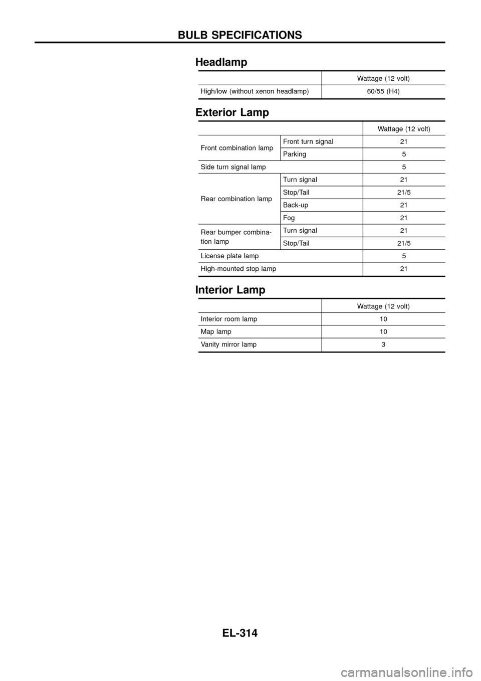
Headlamp
Wattage (12 volt)
High/low (without xenon headlamp) 60/55 (H4)
Exterior Lamp
Wattage (12 volt)
Front combination lampFront turn signal 21
Parking 5
Side turn signal lamp 5
Rear combination lampTurn signal 21
Stop/Tail 21/5
Back-up 21
Fog 21
Rear bumper combina-
tion lampTurn signal 21
Stop/Tail 21/5
License plate lamp 5
High-mounted stop lamp 21
Interior Lamp
Wattage (12 volt)
Interior room lamp 10
Map lamp 10
Vanity mirror lamp 3
BULB SPECIFICATIONS
EL-314