Page 235 of 326
DIAGNOSTIC PROCEDURE 6
(NATS release signal check)
Does engine start properly?
Ye s
cNo
Check NATS system.
CHECK NATS SIGNAL CIRCUIT.
1. Disconnect control unit connector and
NATS IMMU connector.
2. Check continuity between control unit
terminalj
9and NATS IMMU terminal
j
3(LHD models),j7(RHD models).
Continuity should exist.
3. Check continuity between control unit
terminalj
9and ground.
Continuity should not exist.
Refer to wiring diagram in EL-215
(LHD), EL-219 (RHD).
OK
cNG
Repair harness.
CHECK NATS RELEASE SIGNAL.
1. Connect control unit connector and
NATS IMMU connector.
2. Check voltage between control unit ter-
minalj
9and ground.
OK
cNG
Check NATS system.
Replace super lock control unit.
Ignition switch conditionVoltage
[V]
OFF
5
More than 10 seconds after ignition
switch turned ON
For 10 seconds after ignition switch
turned ONPulse
SEL493V
SEL494V
SEL495V
.
.
.
POWER DOOR LOCK Ð Super Lock Ð
Trouble Diagnoses (Cont'd)
EL-231
Page 251 of 326

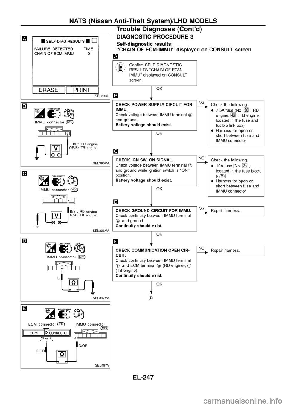
DIAGNOSTIC PROCEDURE 3
Self-diagnostic results:
``CHAIN OF ECM-IMMU'' displayed on CONSULT screen
Con®rm SELF-DIAGNOSTIC
RESULTS ``CHAIN OF ECM-
IMMU'' displayed on CONSULT
screen.
OK
CHECK POWER SUPPLY CIRCUIT FOR
IMMU.
Check voltage between IMMU terminalj
8
and ground.
Battery voltage should exist.
OK
cNG
Check the following.
+7.5A fuse (No.
50:RD
engine,
49: TB engine,
located in the fuse and
fusible link box)
+Harness for open or
short between fuse and
IMMU connector
CHECK IGN SW. ON SIGNAL.
Check voltage between IMMU terminalj
7
and ground while ignition switch is ``ON''
position.
Battery voltage should exist.
OK
cNG
Check the following.
+10A fuse [No.
25,
located in the fuse block
(J/B)]
+Harness for open or
short between fuse and
IMMU connector
CHECK GROUND CIRCUIT FOR IMMU.
Check continuity between IMMU terminal
j
4and ground.
Continuity should exist.
OK
cNG
Repair harness.
CHECK COMMUNICATION OPEN CIR-
CUIT.
Check continuity between IMMU terminal
j
1and ECM terminalj55(RD engine),j11
(TB engine).
Continuity should exist.
OK
cNG
Repair harness.
jA
SEL333U
SEL395VA
SEL396VA
SEL397VA
SEL497V
.
.
.
.
.
NATS (Nissan Anti-Theft System)/LHD MODELS
Trouble Diagnoses (Cont'd)
EL-247
Page 269 of 326

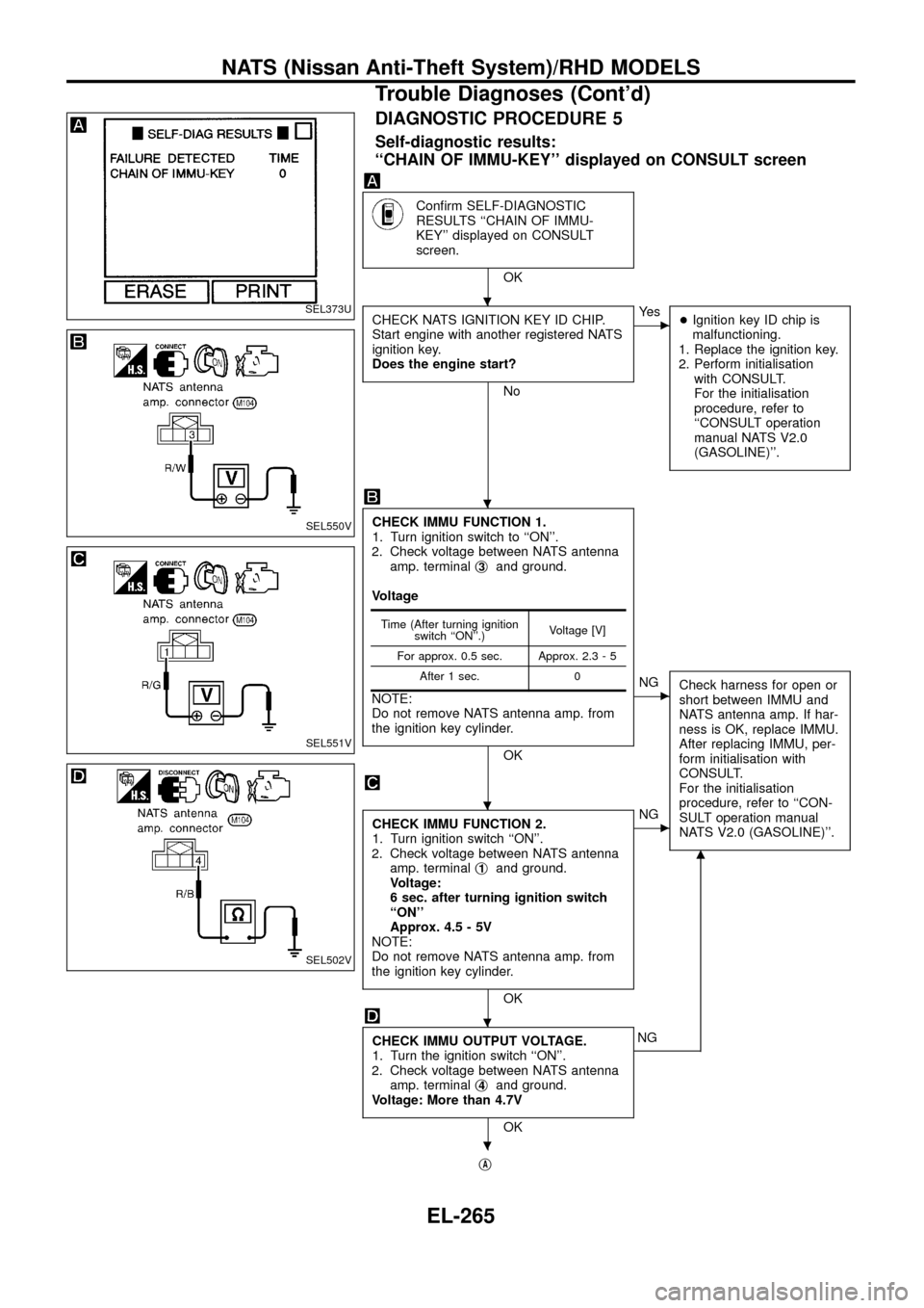
DIAGNOSTIC PROCEDURE 5
Self-diagnostic results:
``CHAIN OF IMMU-KEY'' displayed on CONSULT screen
Con®rm SELF-DIAGNOSTIC
RESULTS ``CHAIN OF IMMU-
KEY'' displayed on CONSULT
screen.
OK
CHECK NATS IGNITION KEY ID CHIP.
Start engine with another registered NATS
ignition key.
Does the engine start?
No
cYe s
+Ignition key ID chip is
malfunctioning.
1. Replace the ignition key.
2. Perform initialisation
with CONSULT.
For the initialisation
procedure, refer to
``CONSULT operation
manual NATS V2.0
(GASOLINE)''.
CHECK IMMU FUNCTION 1.
1. Turn ignition switch to ``ON''.
2. Check voltage between NATS antenna
amp. terminalj
3and ground.
Voltage
NOTE:
Do not remove NATS antenna amp. from
the ignition key cylinder.
OK
cNG
Check harness for open or
short between IMMU and
NATS antenna amp. If har-
ness is OK, replace IMMU.
After replacing IMMU, per-
form initialisation with
CONSULT.
For the initialisation
procedure, refer to ``CON-
SULT operation manual
NATS V2.0 (GASOLINE)''.
CHECK IMMU FUNCTION 2.
1. Turn ignition switch ``ON''.
2. Check voltage between NATS antenna
amp. terminalj
1and ground.
Voltage:
6 sec. after turning ignition switch
``ON''
Approx. 4.5 - 5V
NOTE:
Do not remove NATS antenna amp. from
the ignition key cylinder.
OK
cNG
CHECK IMMU OUTPUT VOLTAGE.
1. Turn the ignition switch ``ON''.
2. Check voltage between NATS antenna
amp. terminalj
4and ground.
Voltage: More than 4.7V
OK
m
NG
j
A
Time (After turning ignition
switch ``ON''.)Voltage [V]
For approx. 0.5 sec. Approx. 2.3 - 5
After 1 sec. 0
SEL373U
SEL550V
SEL551V
SEL502V
.
.
.
.
.
NATS (Nissan Anti-Theft System)/RHD MODELS
Trouble Diagnoses (Cont'd)
EL-265
Page 271 of 326

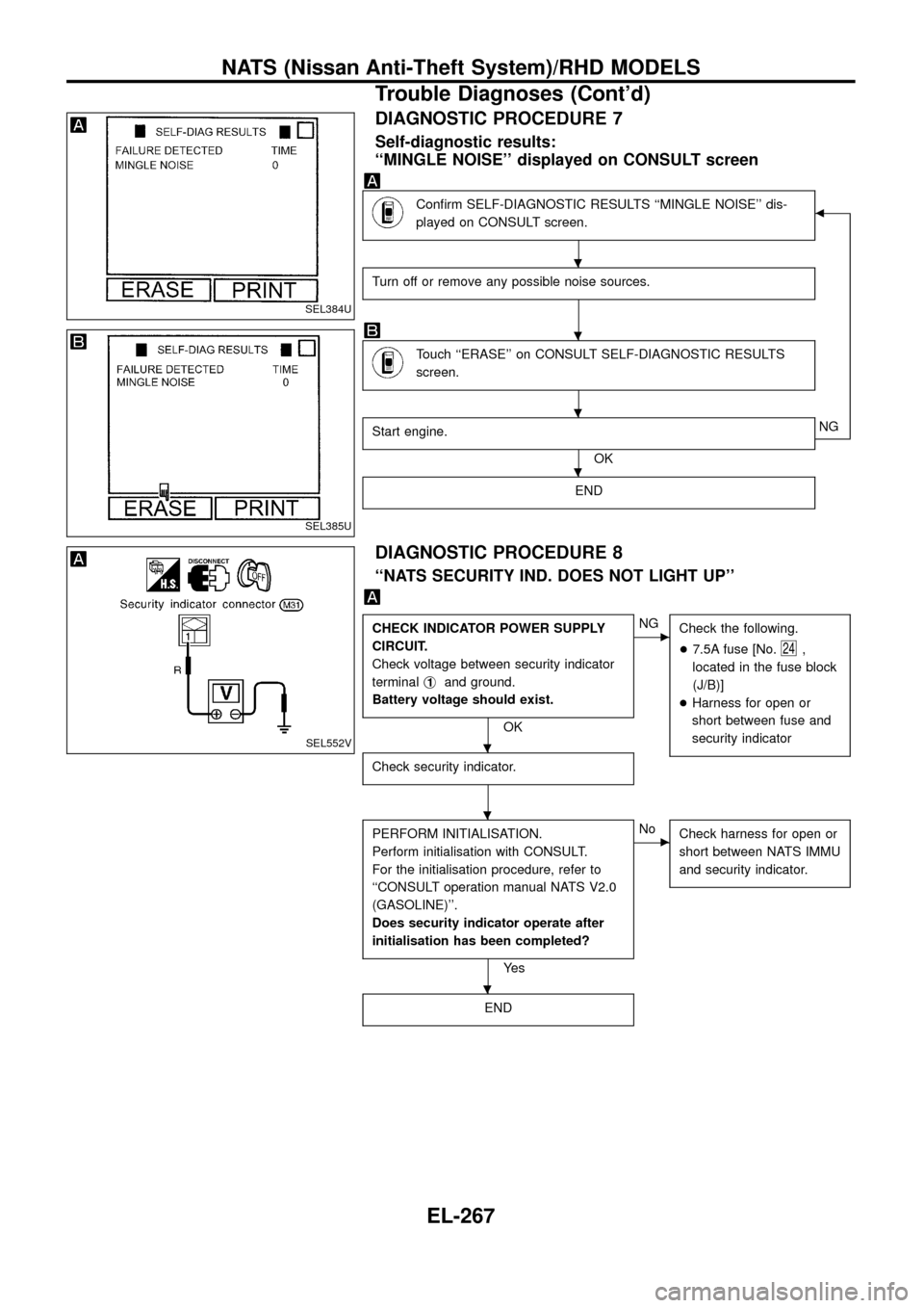
DIAGNOSTIC PROCEDURE 7
Self-diagnostic results:
``MINGLE NOISE'' displayed on CONSULT screen
Con®rm SELF-DIAGNOSTIC RESULTS ``MINGLE NOISE'' dis-
played on CONSULT screen.b
Turn off or remove any possible noise sources.
Touch ``ERASE'' on CONSULT SELF-DIAGNOSTIC RESULTS
screen.
Start engine.
OKNG
END
DIAGNOSTIC PROCEDURE 8
``NATS SECURITY IND. DOES NOT LIGHT UP''
CHECK INDICATOR POWER SUPPLY
CIRCUIT.
Check voltage between security indicator
terminalj
1and ground.
Battery voltage should exist.
OK
cNG
Check the following.
+7.5A fuse [No.
24,
located in the fuse block
(J/B)]
+Harness for open or
short between fuse and
security indicator
Check security indicator.
PERFORM INITIALISATION.
Perform initialisation with CONSULT.
For the initialisation procedure, refer to
``CONSULT operation manual NATS V2.0
(GASOLINE)''.
Does security indicator operate after
initialisation has been completed?
Ye s
cNo
Check harness for open or
short between NATS IMMU
and security indicator.
END
SEL384U
SEL385U
SEL552V
.
.
.
.
.
.
.
NATS (Nissan Anti-Theft System)/RHD MODELS
Trouble Diagnoses (Cont'd)
EL-267
Page 279 of 326
How to Read Harness Layout
Example:
G2E1B/6: ASCD ACTUATOR
Connector color / Cavity
Connector number
Grid reference
The following Harness Layouts use a map style grid to help locate connectors on the drawings:
+Main Harness
+Engine Room Harness (Engine Compartment)
To use the grid reference
1) Find the desired connector number on the connector list.
2) Find the grid reference.
3) On the drawing, ®nd the crossing of the grid reference letter column and number row.
4) Find the connector number in the crossing zone.
5) Follow the line (if used) to the connector.
CONNECTOR SYMBOL
Main symbols of connector (in Harness Layout) are indicated in the below.
Connector typeWater proof type Standard type
Male Female Male Female
+Cavity: Less than 4
+Relay connector
+Cavity: From 5 to 8
+Cavity: More than 9
ÐÐ
+Ground terminal etc.
Ð
HARNESS LAYOUT
EL-275
Page 290 of 326
Engine Room Harness/LHD Models
CEL822
HARNESS LAYOUT
EL-286
Page 291 of 326
CEL823
HARNESS LAYOUT
Engine Room Harness/LHD Models (Cont'd)
EL-287
Page 292 of 326
PASSENGER COMPARTMENT
CEL758
HARNESS LAYOUT
Engine Room Harness/LHD Models (Cont'd)
EL-288