1998 NISSAN PATROL meter gauge operation
[x] Cancel search: meter gauge operationPage 2 of 326

Wiring Diagram Ð H/AIM Ð .....................................71
PARKING, LICENSE AND TAIL LAMPS......................73
Wiring Diagram Ð TAIL/L Ð/Type A .........................73
Wiring Diagram Ð TAIL/L Ð/Type B.........................75
STOP LAMP..................................................................77
Wiring Diagram Ð STOP/L Ð/Type A ......................77
BACK-UP LAMP............................................................78
Wiring Diagram Ð BACK/L Ð/LHD Models..............78
Wiring Diagram Ð BACK/L Ð/RHD Models .............79
REAR FOG LAMP.........................................................80
Wiring Diagram Ð R/FOG Ð ....................................80
TURN SIGNAL AND HAZARD WARNING LAMPS.....81
Wiring Diagram Ð TURN Ð/Type A .........................81
Wiring Diagram Ð TURN Ð/Type B .........................83
Trouble Diagnoses.....................................................85
Electrical Components Inspection .............................85
ILLUMINATION..............................................................86
Schematic ..................................................................86
Wiring Diagram Ð ILL Ð ..........................................87
INTERIOR ROOM LAMP Ð With Timer Ð.................93
System Description ....................................................93
Schematic ..................................................................94
Wiring Diagram Ð ROOM/L Ð/LHD Models ............95
Wiring Diagram Ð ROOM/L Ð/RHD Models............98
Trouble Diagnoses...................................................100
MAP AND VANITY MIRROR LAMPS.........................101
Wiring Diagram Ð INT/L Ð.....................................101
METER AND GAUGES...............................................102
System Description ..................................................102
Combination Meter ..................................................103
Wiring Diagram Ð METER Ð/LHD Models............104
Wiring Diagram Ð METER Ð/RHD Models ...........106
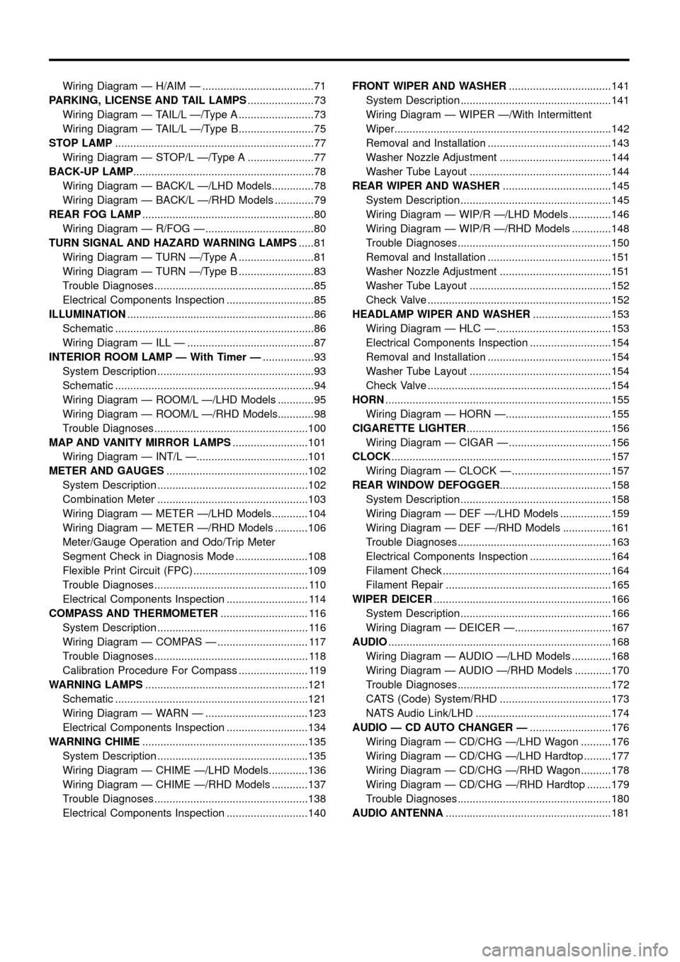
Meter/Gauge Operation and Odo/Trip Meter
Segment Check in Diagnosis Mode ........................108
Flexible Print Circuit (FPC) ......................................109
Trouble Diagnoses................................................... 110
Electrical Components Inspection ........................... 114
COMPASS AND THERMOMETER............................. 116
System Description .................................................. 116
Wiring Diagram Ð COMPAS Ð .............................. 117
Trouble Diagnoses................................................... 118
Calibration Procedure For Compass ....................... 119
WARNING LAMPS......................................................121
Schematic ................................................................121
Wiring Diagram Ð WARN Ð ..................................123
Electrical Components Inspection ...........................134
WARNING CHIME.......................................................135
System Description ..................................................135
Wiring Diagram Ð CHIME Ð/LHD Models.............136
Wiring Diagram Ð CHIME Ð/RHD Models ............137
Trouble Diagnoses...................................................138
Electrical Components Inspection ...........................140FRONT WIPER AND WASHER..................................141
System Description ..................................................141
Wiring Diagram Ð WIPER Ð/With Intermittent
Wiper........................................................................142
Removal and Installation .........................................143
Washer Nozzle Adjustment .....................................144
Washer Tube Layout ...............................................144
REAR WIPER AND WASHER....................................145
System Description ..................................................145
Wiring Diagram Ð WIP/R Ð/LHD Models ..............146
Wiring Diagram Ð WIP/R Ð/RHD Models .............148
Trouble Diagnoses...................................................150
Removal and Installation .........................................151
Washer Nozzle Adjustment .....................................151
Washer Tube Layout ...............................................152
Check Valve .............................................................152
HEADLAMP WIPER AND WASHER..........................153
Wiring Diagram Ð HLC Ð ......................................153
Electrical Components Inspection ...........................154
Removal and Installation .........................................154
Washer Tube Layout ...............................................154
Check Valve .............................................................154
HORN...........................................................................155
Wiring Diagram Ð HORN Ð...................................155
CIGARETTE LIGHTER................................................156
Wiring Diagram Ð CIGAR Ð ..................................156
CLOCK.........................................................................157
Wiring Diagram Ð CLOCK Ð .................................157
REAR WINDOW DEFOGGER.....................................158
System Description ..................................................158
Wiring Diagram Ð DEF Ð/LHD Models .................159
Wiring Diagram Ð DEF Ð/RHD Models ................161
Trouble Diagnoses...................................................163
Electrical Components Inspection ...........................164
Filament Check ........................................................164
Filament Repair .......................................................165
WIPER DEICER...........................................................166
System Description ..................................................166
Wiring Diagram Ð DEICER Ð................................167
AUDIO..........................................................................168
Wiring Diagram Ð AUDIO Ð/LHD Models .............168
Wiring Diagram Ð AUDIO Ð/RHD Models ............170
Trouble Diagnoses...................................................172
CATS (Code) System/RHD .....................................173
NATS Audio Link/LHD .............................................174
AUDIO Ð CD AUTO CHANGER Ð...........................176
Wiring Diagram Ð CD/CHG Ð/LHD Wagon ..........176
Wiring Diagram Ð CD/CHG Ð/LHD Hardtop .........177
Wiring Diagram Ð CD/CHG Ð/RHD Wagon ..........178
Wiring Diagram Ð CD/CHG Ð/RHD Hardtop ........179
Trouble Diagnoses...................................................180
AUDIO ANTENNA.......................................................181
Page 112 of 326

Meter/Gauge Operation and Odo/Trip Meter
Segment Check in Diagnosis Mode
DIAGNOSIS FUNCTION
+Odo/trip meter segment can be checked in diagnosis mode.
+Meters/gauges (except for sub fuel gauge) can be checked in
diagnosis mode.
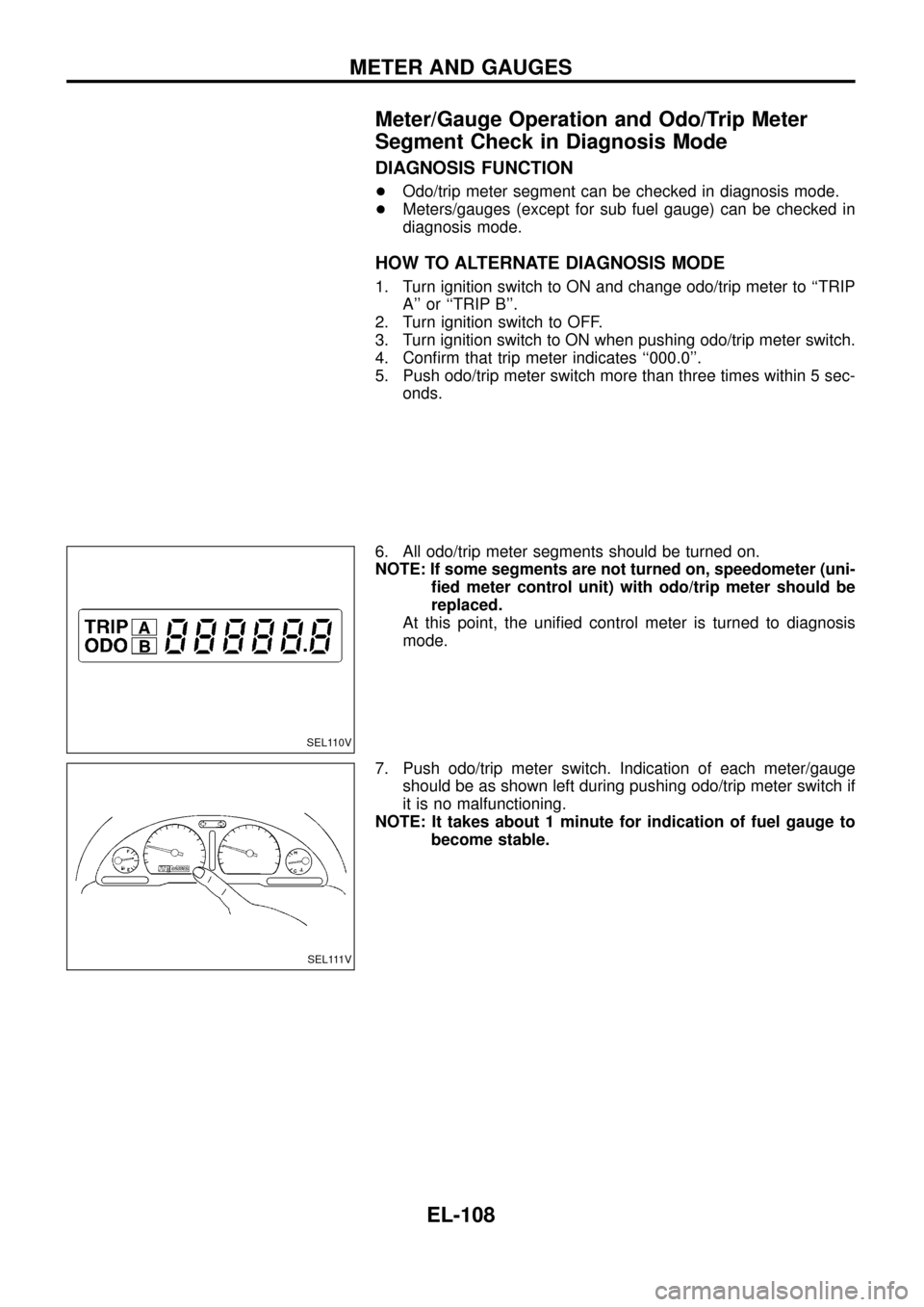
HOW TO ALTERNATE DIAGNOSIS MODE
1. Turn ignition switch to ON and change odo/trip meter to ``TRIP
A'' or ``TRIP B''.
2. Turn ignition switch to OFF.
3. Turn ignition switch to ON when pushing odo/trip meter switch.
4. Con®rm that trip meter indicates ``000.0''.
5. Push odo/trip meter switch more than three times within 5 sec-
onds.
6. All odo/trip meter segments should be turned on.
NOTE: If some segments are not turned on, speedometer (uni-
®ed meter control unit) with odo/trip meter should be
replaced.
At this point, the uni®ed control meter is turned to diagnosis
mode.
7. Push odo/trip meter switch. Indication of each meter/gauge
should be as shown left during pushing odo/trip meter switch if
it is no malfunctioning.
NOTE: It takes about 1 minute for indication of fuel gauge to
become stable.
SEL110V
SEL111V
METER AND GAUGES
EL-108
Page 114 of 326

Trouble Diagnoses
PRELIMINARY CHECK
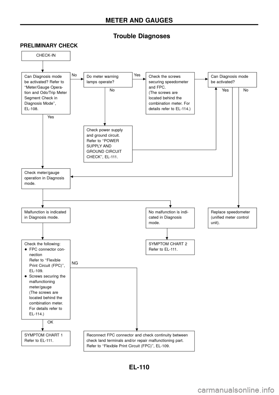
CHECK-IN
Can Diagnosis mode
be activated? Refer to
``Meter/Gauge Opera-
tion and Odo/Trip Meter
Segment Check in
Diagnosis Mode'',
EL-108.
Ye s
cNo
Do meter warning
lamps operate?
No
cYe s
Check the screws
securing speedometer
and FPC.
(The screws are
located behind the
combination meter. For
details refer to EL-114.)cCan Diagnosis mode
be activated?
Nom
Check power supply
and ground circuit.
Refer to ``POWER
SUPPLY AND
GROUND CIRCUIT
CHECK'', EL-111.
Check meter/gauge
operation in Diagnosis
mode.b
Ye s
.
Malfunction is indicated
in Diagnosis mode.No malfunction is indi-
cated in Diagnosis
mode.Replace speedometer
(uni®ed meter control
unit).
Check the following:
+FPC connector con-
nection
Refer to ``Flexible
Print Circuit (FPC)'',
EL-109.
+Screws securing the
malfunctioning
meter/gauge
(The screws are
located behind the
combination meter.
For details refer to
EL-114.)
OK
.
NG
SYMPTOM CHART 2
Refer to EL-111.
SYMPTOM CHART 1
Refer to EL-111.Reconnect FPC connector and check continuity between
check land terminals and/or repair malfunctioning part.
Refer to ``Flexible Print Circuit (FPC)'', EL-109.
.
.
.
..
..
.
METER AND GAUGES
EL-110