Page 153 of 326
TEL656A
REAR WIPER AND WASHER
Wiring Diagram Ð WIP/R Ð/RHD Models
(Cont'd)
EL-149
Page 154 of 326
Trouble Diagnoses
REAR WIPER AMP. INSPECTION TABLE
(Data are reference values.)
Terminal No. Item ConditionVoltage
(Approximate value)
1 Intermittent switch
Rear wiper switchINT Less than 1V
OFF, ON or WASH Approx. 10V
2Wiper motor
(Ground)
Rear wiper switchON Less than 1V
OFF Approx. 12V
3 Ground Ð Ð
4 Washer switch
Rear wiper switchWASH Less than 1V
OFF Approx. 12V
5 Power supply
Ð Approx. 12V
6 Wiper on switch
Rear wiper switchON or WASH Less than 1V
OFF or INT Approx. 12V
7 Wiper amp. output
Rear wiper switch
should be placed in
``WASH'' or ``INT'' to
inspect the value for
wiper movement.Wiper is moving Less than 1V
Wiper stop Approx. 12V
SEL428V
REAR WIPER AND WASHER
EL-150
Page 155 of 326
Removal and Installation
WIPER ARM
1. Prior to wiper arm installation, turn on wiper switch to operate
wiper motor and then turn it ``OFF'' (Auto Stop).
2. Lift the blade up and then set it down onto glass surface. Set
the blade center to clearance ``E'' immediately before tighten-
ing nut.
3. Eject washer ¯uid. Turn on wiper switch to operate wiper motor
and then turn it ``OFF''.
4. Ensure that wiper blades stop within clearance ``E''.
Clearance ``E'': 20 mm (0.79 in)
+Tighten windshield wiper arm nuts to speci®ed torque.
:13-18Nzm (1.3 - 1.8 kg-m,9-13ft-lb)
+Before reinstalling wiper arm, clean up the pivot area as
illustrated. This will reduce possibility of wiper arm loose-
ness.
Washer Nozzle Adjustment
+Adjust washer nozzle with suitable tool as shown in the ®gure
at left.
Adjustable range: 10É (In any direction)
Unit: mm (in)
*1 30 (1.18) *3 40 (1.57)
*2 30 (1.18) *4 20 (0.79)
CEL779
SEL024J
SEL241P
CEL780
REAR WIPER AND WASHER
EL-151
Page 156 of 326
Washer Tube Layout
Check Valve
+A check valve is provided in the washer ¯uid line. Be careful not
to connect check valve to washer tube in the wrong direction.
CEL743
SEL411H
REAR WIPER AND WASHER
EL-152
Page 157 of 326
Wiring Diagram Ð HLC Ð
TEL694A
HEADLAMP WIPER AND WASHER
EL-153
Page 158 of 326

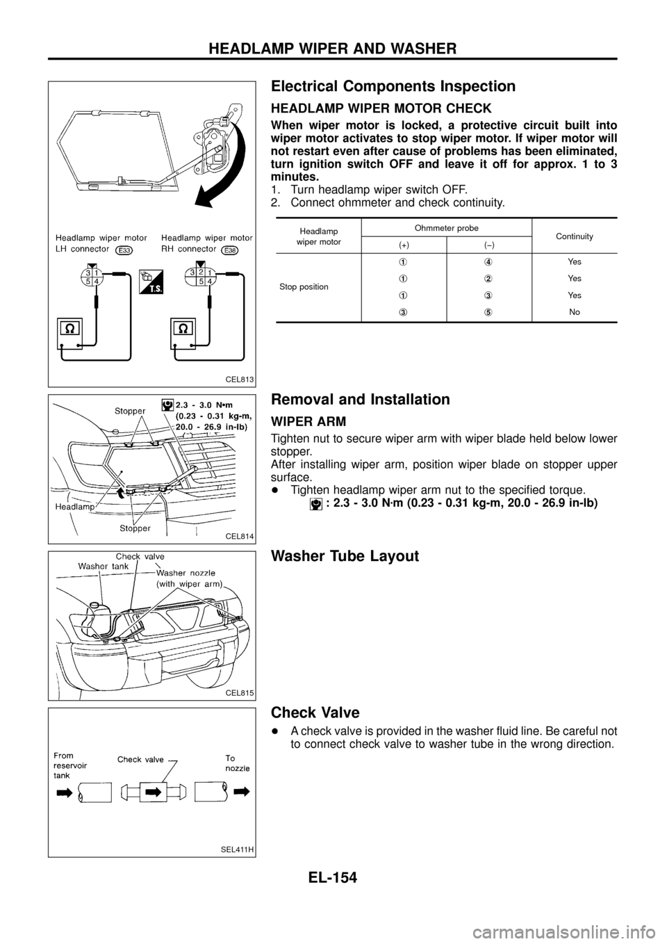
Electrical Components Inspection
HEADLAMP WIPER MOTOR CHECK
When wiper motor is locked, a protective circuit built into
wiper motor activates to stop wiper motor. If wiper motor will
not restart even after cause of problems has been eliminated,
turn ignition switch OFF and leave it off for approx. 1 to 3
minutes.
1. Turn headlamp wiper switch OFF.
2. Connect ohmmeter and check continuity.
Headlamp
wiper motorOhmmeter probe
Continuity
(+) (þ)
Stop positionj
1j4Ye s
j
1j2Ye s
j
1j3Ye s
j
3j5No
Removal and Installation
WIPER ARM
Tighten nut to secure wiper arm with wiper blade held below lower
stopper.
After installing wiper arm, position wiper blade on stopper upper
surface.
+Tighten headlamp wiper arm nut to the speci®ed torque.
: 2.3 - 3.0 Nzm (0.23 - 0.31 kg-m, 20.0 - 26.9 in-lb)
Washer Tube Layout
Check Valve
+A check valve is provided in the washer ¯uid line. Be careful not
to connect check valve to washer tube in the wrong direction.
CEL813
CEL814
CEL815
SEL411H
HEADLAMP WIPER AND WASHER
EL-154
Page 159 of 326
Wiring Diagram Ð HORN Ð
TEL446A
HORN
EL-155
Page 160 of 326
Wiring Diagram Ð CIGAR Ð
TEL447A
CIGARETTE LIGHTER
EL-156