Page 145 of 326

System Description
WIPER OPERATION
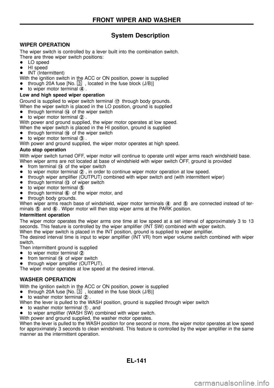
The wiper switch is controlled by a lever built into the combination switch.
There are three wiper switch positions:
+LO speed
+HI speed
+INT (Intermittent)
With the ignition switch in the ACC or ON position, power is supplied
+through 20A fuse [No.
, located in the fuse block (J/B)]
+to wiper motor terminalj
4.
Low and high speed wiper operation
Ground is supplied to wiper switch terminalj
17through body grounds.
When the wiper switch is placed in the LO position, ground is supplied
+through terminalj
14of the wiper switch
+to wiper motor terminalj
2.
With power and ground supplied, the wiper motor operates at low speed.
When the wiper switch is placed in the HI position, ground is supplied
+through terminalj
16of the wiper switch
+to wiper motor terminalj
3.
With power and ground supplied, the wiper motor operates at high speed.
Auto stop operation
With wiper switch turned OFF, wiper motor will continue to operate until wiper arms reach windshield base.
When wiper arms are not located at base of windshield with wiper switch OFF, ground is provided
+from terminalj
14of the wiper switch
+to wiper motor terminalj
2, in order to continue wiper motor operation at low speed.
+through wiper ampli®er (OUTPUT) combined with wiper switch and (with intermittent wiper)
+through terminalj
13of wiper switch
+to wiper motor terminalj
5
+through terminalj6of the wiper motor, and
+through body grounds.
When wiper arms reach base of windshield, wiper motor terminalsj
4andj5are connected instead of ter-
minalsj
5andj6. Wiper motor will then stop wiper arms at the PARK position.
Intermittent operation
The wiper motor operates the wiper arms one time at low speed at a set interval of approximately 3 to 13
seconds. This feature is controlled by the wiper ampli®er (INT SW) combined with wiper switch.
When the wiper switch is placed in the INT position, ground is supplied to wiper ampli®er.
The desired interval time is input to wiper ampli®er (INT VR) from wiper volume switch combined with wiper
switch.
Then intermittent ground is supplied
+to wiper motor terminalj
2
+from terminalj14of wiper switch
+through wiper ampli®er (OUTPUT).
The wiper motor operates at low speed at the desired interval.
WASHER OPERATION
With the ignition switch in the ACC or ON position, power is supplied
+through 20A fuse [No.
, located in the fuse block (J/B)]
+to washer motor terminalj
2.
When the lever is pulled to the WASH position, ground is supplied through wiper switch
+to washer motor terminalj
1, and
+to wiper ampli®er (WASH SW) combined with wiper switch.
With power and ground supplied, the washer motor operates.
When the lever is pulled to the WASH position for one second or more, the wiper motor operates at low speed
for approximately 3 seconds to clean windshield. This feature is controlled by the wiper ampli®er in the same
manner as the intermittent operation.
FRONT WIPER AND WASHER
EL-141
Page 146 of 326
Wiring Diagram Ð WIPER Ð/With Intermittent
Wiper
TEL442A
FRONT WIPER AND WASHER
EL-142
Page 147 of 326
Removal and Installation
WIPER ARMS
1. Prior to wiper arm installation, turn on wiper switch to operate
wiper motor and then turn it ``OFF'' (Auto Stop).
2. Lift the blade up and then set it down onto glass surface to set
the blade center to clearance ``L
1''&``L2'' immediately before
tightening nut.
3. Eject washer ¯uid. Turn on wiper switch to operate wiper motor
and then turn it ``OFF''.
4. Ensure that wiper blades stop within clearance ``L
1''&``L2''.
Clearance ``L
1'': 25 mm (0.98 in)
Clearance ``L
2'': 23 mm (0.91 in)
+Tighten wiper arm nuts to speci®ed torque.
Front wiper: 21 - 26 Nzm (2.1 - 2.7 kg-m, 15 - 20 ft-lb)
+Before reinstalling wiper arm, clean up the pivot area as
illustrated. This will reduce possibility of wiper arm loose-
ness.
WIPER LINKAGE
SEL543TA
SEL024J
CEL741
FRONT WIPER AND WASHER
EL-143
Page 148 of 326
Removal
1. Remove 4 bolts that secure wiper motor.
2. Detach wiper motor from wiper linkage at ball joint.
3. Remove wiper linkage.
Be careful not to break ball joint rubber boot.
Installation
+Grease ball joint portion before installation.
1. Installation is the reverse order of removal.
Washer Nozzle Adjustment
+Adjust washer nozzle with suitable tool as shown in the ®gure
at left.
Adjustable range: 10É
Unit: mm (in)
*1 180 (7.09) *5 70 (2.76)
*2 170 (6.69) *6 40 (1.57)
*3 290 (11.42) *7 370 (14.57)
*4 200 (7.87) *8 470 (18.50)
*: The diameters of these circles are less than 100 mm (3.94 in).
Washer Tube Layout
SEL241P
SEL544T
CEL742
FRONT WIPER AND WASHER
Removal and Installation (Cont'd)
EL-144
Page 149 of 326

System Description
WIPER OPERATION
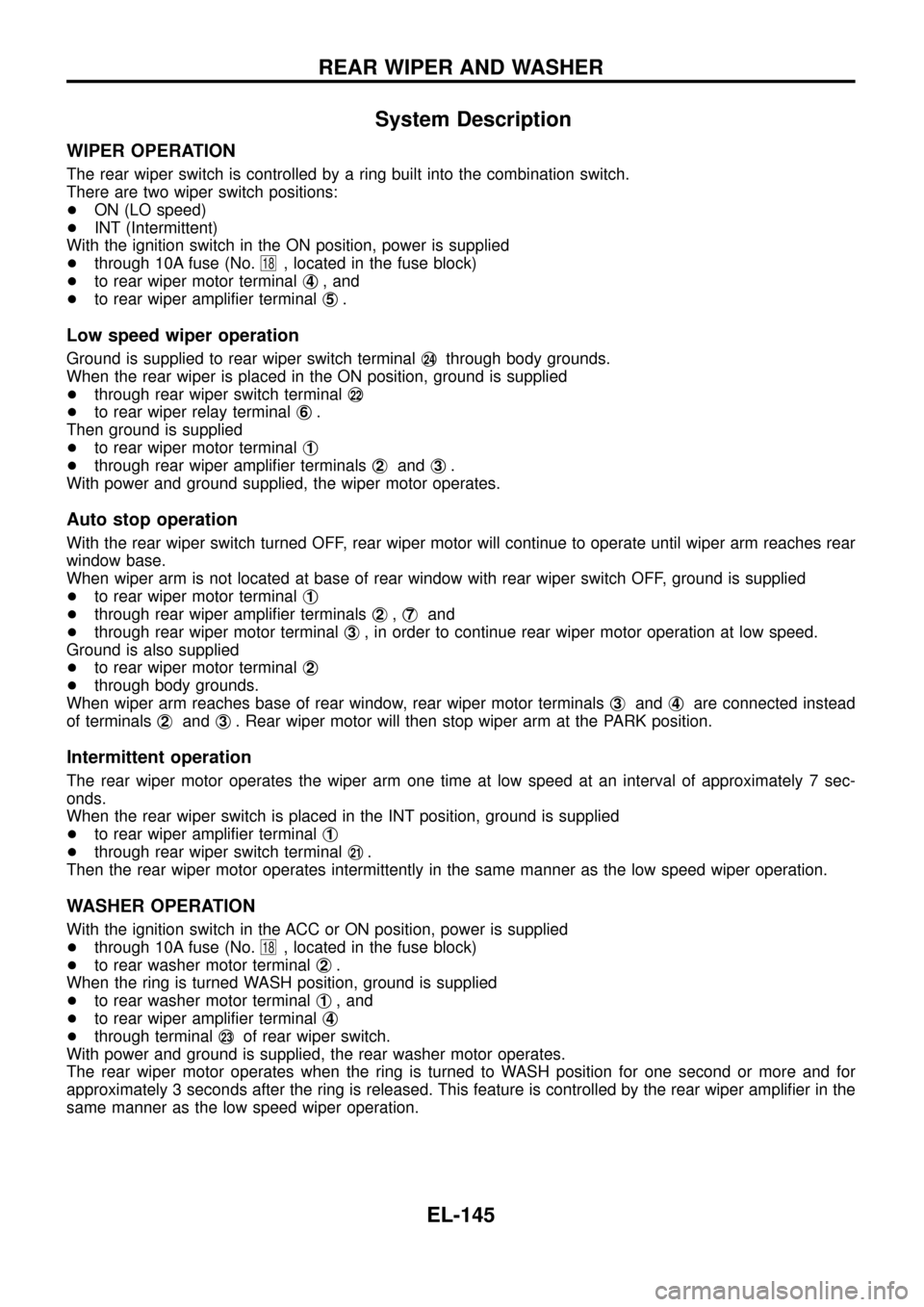
The rear wiper switch is controlled by a ring built into the combination switch.
There are two wiper switch positions:
+ON (LO speed)
+INT (Intermittent)
With the ignition switch in the ON position, power is supplied
+through 10A fuse (No.
18, located in the fuse block)
+to rear wiper motor terminalj
4, and
+to rear wiper ampli®er terminalj
5.
Low speed wiper operation
Ground is supplied to rear wiper switch terminalj24through body grounds.
When the rear wiper is placed in the ON position, ground is supplied
+through rear wiper switch terminalj
22
+to rear wiper relay terminalj6.
Then ground is supplied
+to rear wiper motor terminalj
1
+through rear wiper ampli®er terminalsj2andj3.
With power and ground supplied, the wiper motor operates.
Auto stop operation
With the rear wiper switch turned OFF, rear wiper motor will continue to operate until wiper arm reaches rear
window base.
When wiper arm is not located at base of rear window with rear wiper switch OFF, ground is supplied
+to rear wiper motor terminalj
1
+through rear wiper ampli®er terminalsj2,j7and
+through rear wiper motor terminalj
3, in order to continue rear wiper motor operation at low speed.
Ground is also supplied
+to rear wiper motor terminalj
2
+through body grounds.
When wiper arm reaches base of rear window, rear wiper motor terminalsj
3andj4are connected instead
of terminalsj
2andj3. Rear wiper motor will then stop wiper arm at the PARK position.
Intermittent operation
The rear wiper motor operates the wiper arm one time at low speed at an interval of approximately 7 sec-
onds.
When the rear wiper switch is placed in the INT position, ground is supplied
+to rear wiper ampli®er terminalj
1
+through rear wiper switch terminalj21.
Then the rear wiper motor operates intermittently in the same manner as the low speed wiper operation.
WASHER OPERATION
With the ignition switch in the ACC or ON position, power is supplied
+through 10A fuse (No.
18, located in the fuse block)
+to rear washer motor terminalj
2.
When the ring is turned WASH position, ground is supplied
+to rear washer motor terminalj
1, and
+to rear wiper ampli®er terminalj
4
+through terminalj23of rear wiper switch.
With power and ground is supplied, the rear washer motor operates.
The rear wiper motor operates when the ring is turned to WASH position for one second or more and for
approximately 3 seconds after the ring is released. This feature is controlled by the rear wiper ampli®er in the
same manner as the low speed wiper operation.
REAR WIPER AND WASHER
EL-145
Page 150 of 326
Wiring Diagram Ð WIP/R Ð/LHD Models
TEL444A
REAR WIPER AND WASHER
EL-146
Page 151 of 326
TEL445A
REAR WIPER AND WASHER
Wiring Diagram Ð WIP/R Ð/LHD Models
(Cont'd)
EL-147
Page 152 of 326
Wiring Diagram Ð WIP/R Ð/RHD Models
TEL655A
REAR WIPER AND WASHER
EL-148