1998 NISSAN PATROL air con
[x] Cancel search: air conPage 114 of 326
Trouble Diagnoses
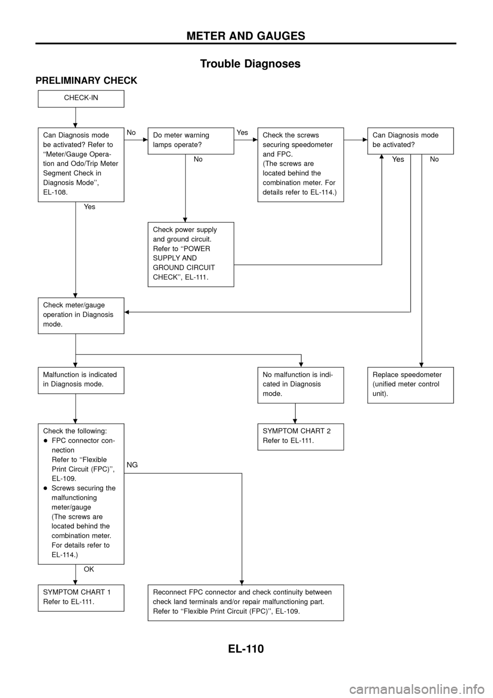
PRELIMINARY CHECK
CHECK-IN
Can Diagnosis mode
be activated? Refer to
``Meter/Gauge Opera-
tion and Odo/Trip Meter
Segment Check in
Diagnosis Mode'',
EL-108.
Ye s
cNo
Do meter warning
lamps operate?
No
cYe s
Check the screws
securing speedometer
and FPC.
(The screws are
located behind the
combination meter. For
details refer to EL-114.)cCan Diagnosis mode
be activated?
Nom
Check power supply
and ground circuit.
Refer to ``POWER
SUPPLY AND
GROUND CIRCUIT
CHECK'', EL-111.
Check meter/gauge
operation in Diagnosis
mode.b
Ye s
.
Malfunction is indicated
in Diagnosis mode.No malfunction is indi-
cated in Diagnosis
mode.Replace speedometer
(uni®ed meter control
unit).
Check the following:
+FPC connector con-
nection
Refer to ``Flexible
Print Circuit (FPC)'',
EL-109.
+Screws securing the
malfunctioning
meter/gauge
(The screws are
located behind the
combination meter.
For details refer to
EL-114.)
OK
.
NG
SYMPTOM CHART 2
Refer to EL-111.
SYMPTOM CHART 1
Refer to EL-111.Reconnect FPC connector and check continuity between
check land terminals and/or repair malfunctioning part.
Refer to ``Flexible Print Circuit (FPC)'', EL-109.
.
.
.
..
..
.
METER AND GAUGES
EL-110
Page 115 of 326
SYMPTOM CHART
Symptom chart 1 (Malfunction is indicated in Diagnosis mode)
Symptom Possible causes Repair order
Speedometer and/or odo/trip
meter indicate(s) malfunction
in Diagnosis mode.+Speedometer (Uni®ed meter control unit)+Replace speedometer (uni®ed meter control unit).
Multiple meter/gauge indicate
malfunction in Diagnosis
mode.
One of tachometer/fuel gauge/
water temp. gauge indicates
malfunction in Diagnosis
mode.+Meter/Gauge
+Speedometer (Uni®ed meter control unit)1. Check resistance of meter/gauge indicating malfunction. If
the resistance is NG, replace the meter/gauge. Refer to
``METER/GAUGE RESISTANCE CHECK'', EL-114.
2. If the resistance is OK, replace speedometer (uni®ed meter
control unit).
Symptom chart 2 (No malfunction is indicated in Diagnosis mode)
Symptom Possible causes Repair order
Speedometer and odo/trip
meter are malfunctioning.1. Sensor
- Speedometer, Odo/Trip meter
2. FPC connector
3. Speedometer (Uni®ed meter control unit)1. Check vehicle speed sensor.
INSPECTION/VEHICLE SPEED SENSOR (Refer to EL-112.)
2. Check FPC connector. Refer to ``Flexible Print Circuit
(FPC)'', EL-109.
3. Replace speedometer (uni®ed meter control unit).
Multiple meter/gauge are mal-
functioning. (except
speedometer, odo/trip meter)1. FPC connector
2. Speedometer (Uni®ed meter control unit)1. Check FPC connector. Refer to ``Flexible Print Circuit
(FPC)'', EL-109.
2. Replace speedometer (uni®ed meter control unit).
One of tachometer/fuel gauge/
water temp. gauge is malfunc-
tioning.1. Sensor/Engine revolution signal
- Tachometer
- Fuel gauge
- Water temp. gauge
2. FPC connector
3. Speedometer (Uni®ed meter control unit)1. Check the sensor for malfunctioning meter/gauge.
INSPECTION/ENGINE REVOLUTION SIGNAL (Refer to
EL-113.)
INSPECTION/FUEL TANK GAUGE (Refer to EL-113.)
INSPECTION/THERMAL TRANSMITTER (Refer to EL-114.)
2. Check FPC connector. Refer to ``Flexible Print Circuit
(FPC)'', EL-109.
3. Replace speedometer (uni®ed meter control unit).
Before starting trouble diagnoses above, perform PRELIMINARY CHECK, EL-110.
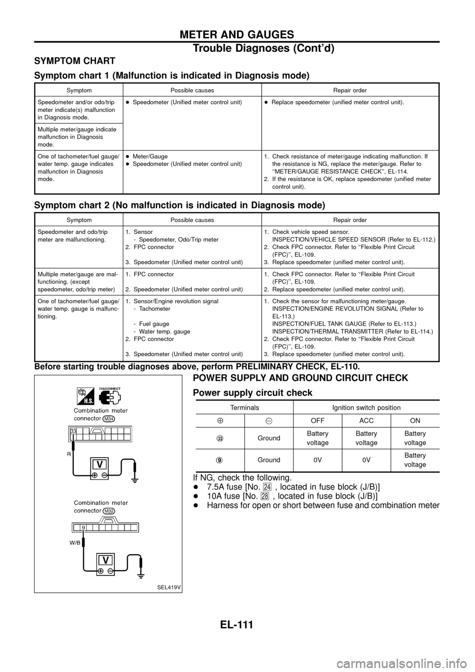
POWER SUPPLY AND GROUND CIRCUIT CHECK
Power supply circuit check
Terminals Ignition switch position
Å@OFF ACC ON
j
33GroundBattery
voltageBattery
voltageBattery
voltage
j
9Ground 0V 0VBattery
voltage
If NG, check the following.
+7.5A fuse [No.
24, located in fuse block (J/B)]
+10A fuse [No.
28, located in fuse block (J/B)]
+Harness for open or short between fuse and combination meter
SEL419V
METER AND GAUGES
Trouble Diagnoses (Cont'd)
EL-111
Page 117 of 326
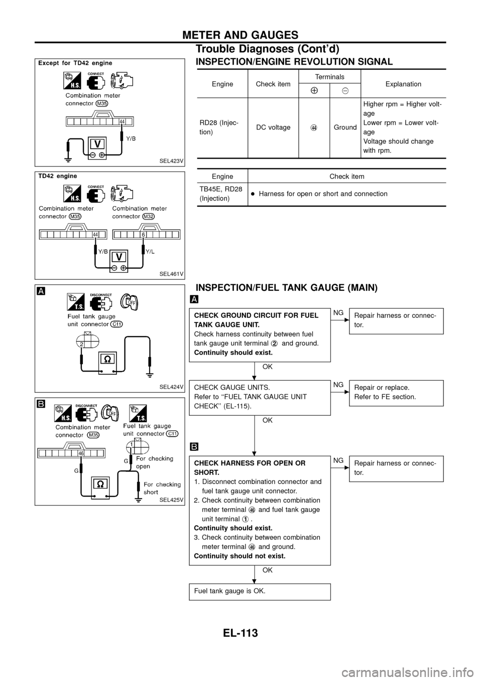
INSPECTION/ENGINE REVOLUTION SIGNAL
Engine Check itemTerminals
ExplanationÅ@
RD28 (Injec-
tion)DC voltagej
44GroundHigher rpm = Higher volt-
age
Lower rpm = Lower volt-
age
Voltage should change
with rpm.
Engine Check item
TB45E, RD28
(Injection)+Harness for open or short and connection
INSPECTION/FUEL TANK GAUGE (MAIN)
CHECK GROUND CIRCUIT FOR FUEL
TANK GAUGE UNIT.
Check harness continuity between fuel
tank gauge unit terminalj
2and ground.
Continuity should exist.
OK
cNG
Repair harness or connec-
tor.
CHECK GAUGE UNITS.
Refer to ``FUEL TANK GAUGE UNIT
CHECK'' (EL-115).
OK
cNG
Repair or replace.
Refer to FE section.
CHECK HARNESS FOR OPEN OR
SHORT.
1. Disconnect combination connector and
fuel tank gauge unit connector.
2. Check continuity between combination
meter terminalj
46and fuel tank gauge
unit terminalj
1.
Continuity should exist.
3. Check continuity between combination
meter terminalj
46and ground.
Continuity should not exist.
OK
cNG
Repair harness or connec-
tor.
Fuel tank gauge is OK.
SEL423V
SEL461V
SEL424V
SEL425V
.
.
.
METER AND GAUGES
Trouble Diagnoses (Cont'd)
EL-113
Page 118 of 326
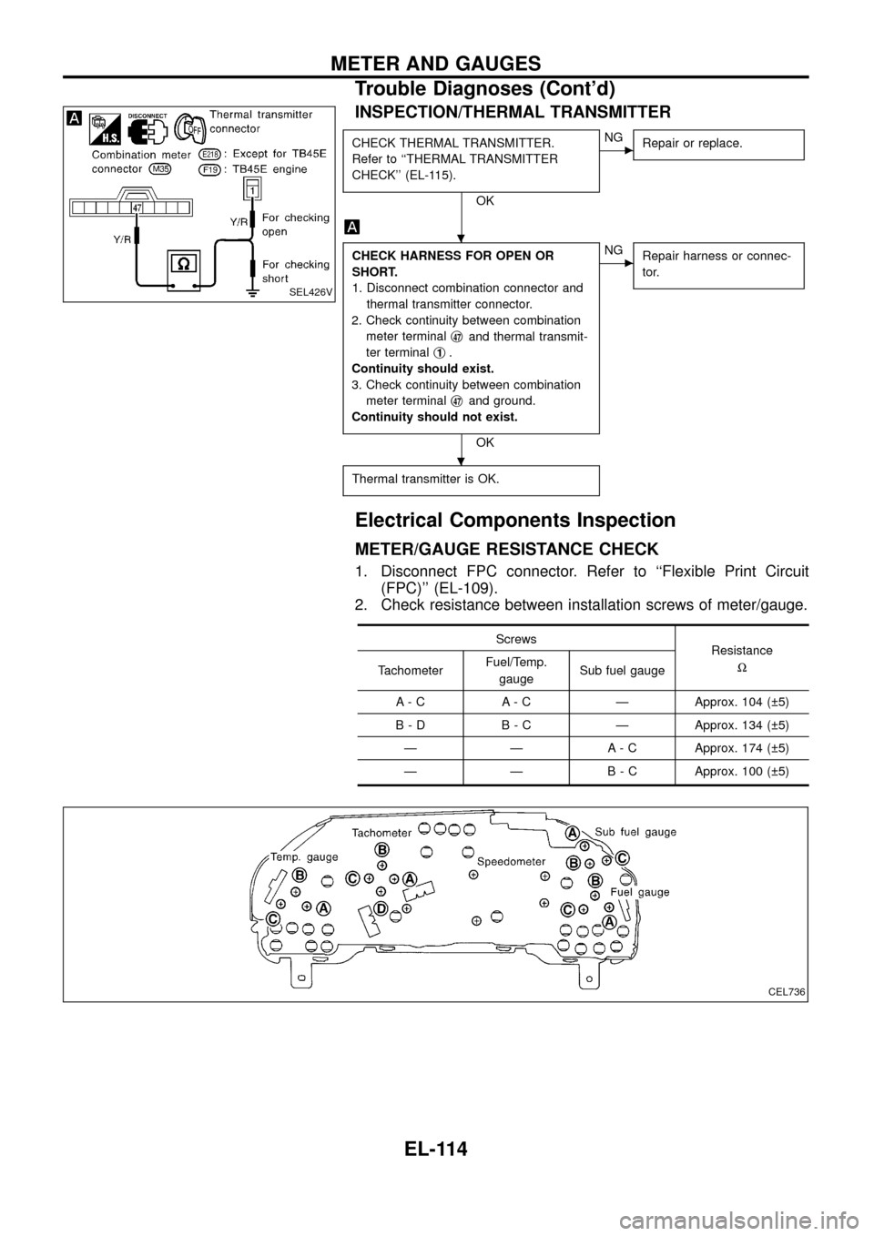
INSPECTION/THERMAL TRANSMITTER
CHECK THERMAL TRANSMITTER.
Refer to ``THERMAL TRANSMITTER
CHECK'' (EL-115).
OK
cNG
Repair or replace.
CHECK HARNESS FOR OPEN OR
SHORT.
1. Disconnect combination connector and
thermal transmitter connector.
2. Check continuity between combination
meter terminalj
47and thermal transmit-
ter terminalj
1.
Continuity should exist.
3. Check continuity between combination
meter terminalj
47and ground.
Continuity should not exist.
OK
cNG
Repair harness or connec-
tor.
Thermal transmitter is OK.
Electrical Components Inspection
METER/GAUGE RESISTANCE CHECK
1. Disconnect FPC connector. Refer to ``Flexible Print Circuit
(FPC)'' (EL-109).
2. Check resistance between installation screws of meter/gauge.
Screws
Resistance
W
TachometerFuel/Temp.
gaugeSub fuel gauge
A - C A - C Ð Approx. 104 ( 5)
B - D B - C Ð Approx. 134 ( 5)
Ð Ð A - C Approx. 174 ( 5)
Ð Ð B - C Approx. 100 ( 5)
SEL426V
CEL736
.
.
METER AND GAUGES
Trouble Diagnoses (Cont'd)
EL-114
Page 120 of 326
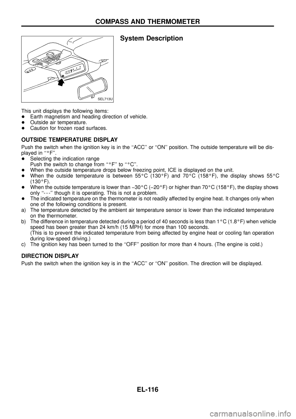
System Description
This unit displays the following items:
+Earth magnetism and heading direction of vehicle.
+Outside air temperature.
+Caution for frozen road surfaces.
OUTSIDE TEMPERATURE DISPLAY
Push the switch when the ignition key is in the ``ACC'' or ``ON'' position. The outside temperature will be dis-
played in ``ÉF''.
+Selecting the indication range
Push the switch to change from ``ÉF'' to ``ÉC''.
+When the outside temperature drops below freezing point, ICE is displayed on the unit.
+When the outside temperature is between 55ÉC (130ÉF) and 70ÉC (158ÉF), the display shows 55ÉC
(130ÉF).
+When the outside temperature is lower than þ30ÉC (þ20ÉF) or higher than 70ÉC (158ÉF), the display shows
only ``- - -'' though it is operating. This is not a problem.
+The indicated temperature on the thermometer is not readily affected by engine heat. It changes only when
one of the following conditions is present.
a) The temperature detected by the ambient air temperature sensor is lower than the indicated temperature
on the thermometer.
b) The difference in temperature detected during a period of 40 seconds is less than 1ÉC (1.8ÉF) when vehicle
speed has been greater than 24 km/h (15 MPH) for more than 100 seconds.
(This is to prevent the indicated temperature from being affected by engine heat or cooling fan operation
during low-speed driving.)
c) The ignition key has been turned to the ``OFF'' position for more than 4 hours. (The engine is cold.)
DIRECTION DISPLAY
Push the switch when the ignition key is in the ``ACC'' or ``ON'' position. The direction will be displayed.
SEL713U
COMPASS AND THERMOMETER
EL-116
Page 122 of 326
Trouble Diagnoses
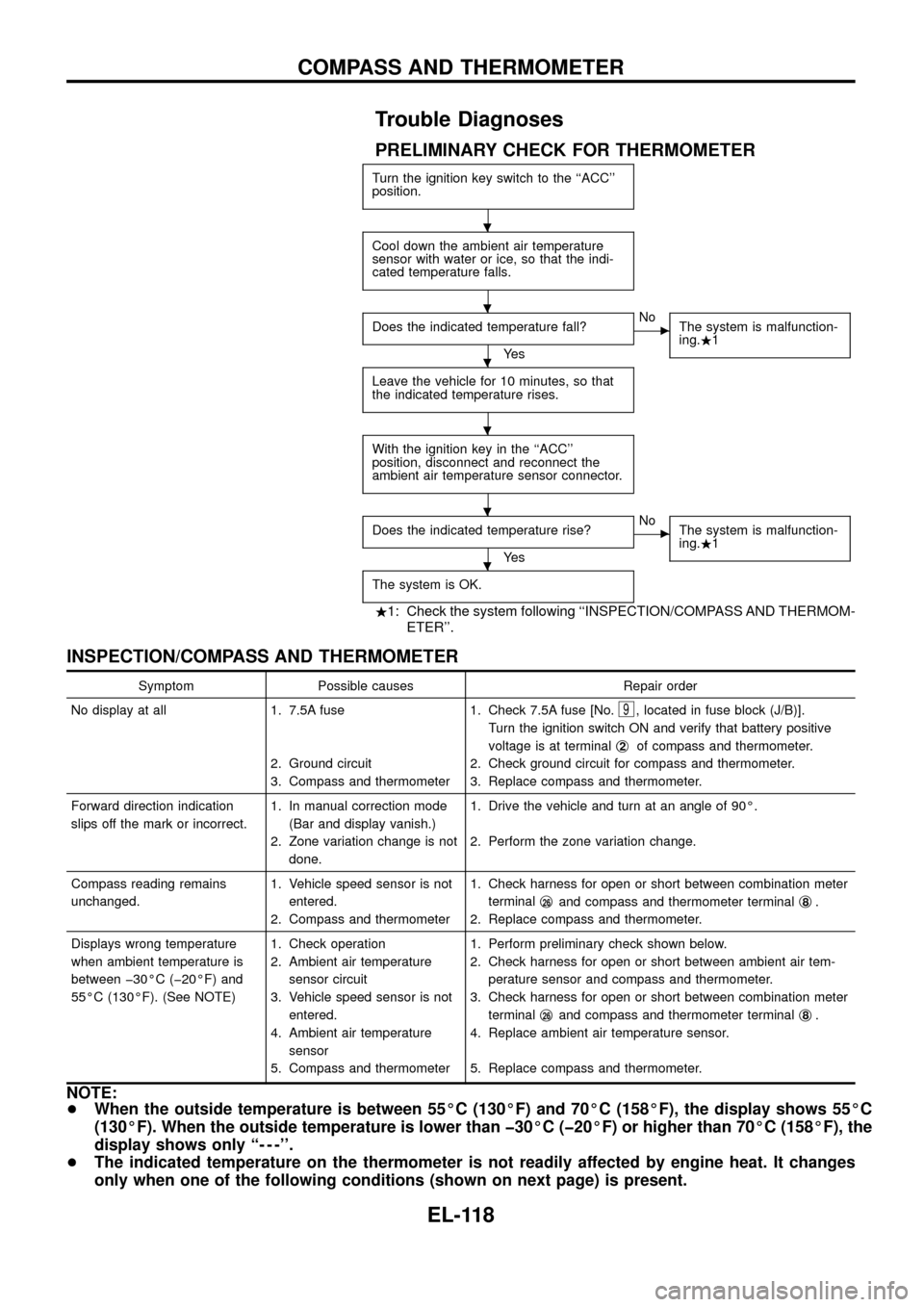
PRELIMINARY CHECK FOR THERMOMETER
Turn the ignition key switch to the ``ACC''
position.
Cool down the ambient air temperature
sensor with water or ice, so that the indi-
cated temperature falls.
Does the indicated temperature fall?
Ye s
cNo
The system is malfunction-
ing..1
Leave the vehicle for 10 minutes, so that
the indicated temperature rises.
With the ignition key in the ``ACC''
position, disconnect and reconnect the
ambient air temperature sensor connector.
Does the indicated temperature rise?
Ye s
cNo
The system is malfunction-
ing..1
The system is OK.
.1: Check the system following ``INSPECTION/COMPASS AND THERMOM-
ETER''.
INSPECTION/COMPASS AND THERMOMETER
Symptom Possible causes Repair order
No display at all 1. 7.5A fuse
2. Ground circuit
3. Compass and thermometer1. Check 7.5A fuse [No.
9, located in fuse block (J/B)].
Turn the ignition switch ON and verify that battery positive
voltage is at terminalj
2of compass and thermometer.
2. Check ground circuit for compass and thermometer.
3. Replace compass and thermometer.
Forward direction indication
slips off the mark or incorrect.1. In manual correction mode
(Bar and display vanish.)
2. Zone variation change is not
done.1. Drive the vehicle and turn at an angle of 90É.
2. Perform the zone variation change.
Compass reading remains
unchanged.1. Vehicle speed sensor is not
entered.
2. Compass and thermometer1. Check harness for open or short between combination meter
terminalj
26and compass and thermometer terminalj8.
2. Replace compass and thermometer.
Displays wrong temperature
when ambient temperature is
between þ30ÉC (þ20ÉF) and
55ÉC (130ÉF). (See NOTE)1. Check operation
2. Ambient air temperature
sensor circuit
3. Vehicle speed sensor is not
entered.
4. Ambient air temperature
sensor
5. Compass and thermometer1. Perform preliminary check shown below.
2. Check harness for open or short between ambient air tem-
perature sensor and compass and thermometer.
3. Check harness for open or short between combination meter
terminalj
26and compass and thermometer terminalj8.
4. Replace ambient air temperature sensor.
5. Replace compass and thermometer.
NOTE:
+When the outside temperature is between 55ÉC (130ÉF) and 70ÉC (158ÉF), the display shows 55ÉC
(130ÉF). When the outside temperature is lower than þ30ÉC (þ20ÉF) or higher than 70ÉC (158ÉF), the
display shows only ``- - -''.
+The indicated temperature on the thermometer is not readily affected by engine heat. It changes
only when one of the following conditions (shown on next page) is present.
.
.
.
.
.
.
COMPASS AND THERMOMETER
EL-118
Page 123 of 326
a) The temperature detected by the ambient air temperature sensor is lower than the indicated tem-
perature on the thermometer.
b) The difference in temperature detected during a period of 40 seconds is less than 1ÉC (1.8ÉF) when
vehicle speed has been greater than 24 km/h (15 MPH) for more than 100 seconds.
(This is to prevent the indicated temperature from being affected by engine heat or cooling fan
operation during low-speed driving.)
c) The ignition key has been turned to the ``OFF'' position for more than 4 hours. (The engine is cold.)
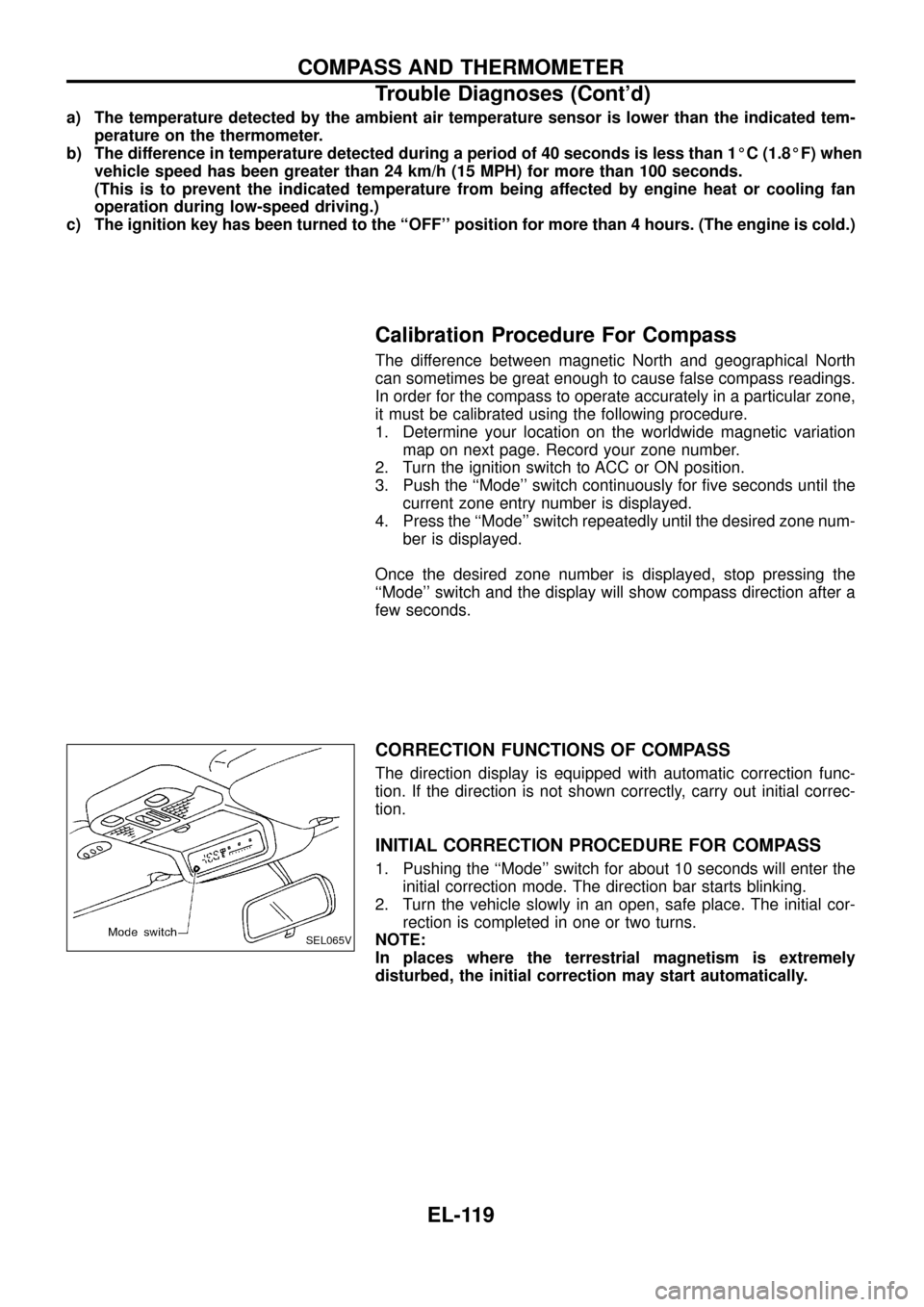
Calibration Procedure For Compass
The difference between magnetic North and geographical North
can sometimes be great enough to cause false compass readings.
In order for the compass to operate accurately in a particular zone,
it must be calibrated using the following procedure.
1. Determine your location on the worldwide magnetic variation
map on next page. Record your zone number.
2. Turn the ignition switch to ACC or ON position.
3. Push the ``Mode'' switch continuously for ®ve seconds until the
current zone entry number is displayed.
4. Press the ``Mode'' switch repeatedly until the desired zone num-
ber is displayed.
Once the desired zone number is displayed, stop pressing the
``Mode'' switch and the display will show compass direction after a
few seconds.
CORRECTION FUNCTIONS OF COMPASS
The direction display is equipped with automatic correction func-
tion. If the direction is not shown correctly, carry out initial correc-
tion.
INITIAL CORRECTION PROCEDURE FOR COMPASS
1. Pushing the ``Mode'' switch for about 10 seconds will enter the
initial correction mode. The direction bar starts blinking.
2. Turn the vehicle slowly in an open, safe place. The initial cor-
rection is completed in one or two turns.
NOTE:
In places where the terrestrial magnetism is extremely
disturbed, the initial correction may start automatically.
SEL065V
COMPASS AND THERMOMETER
Trouble Diagnoses (Cont'd)
EL-119
Page 143 of 326
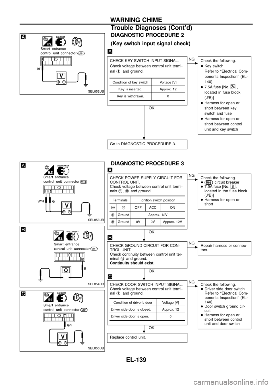
DIAGNOSTIC PROCEDURE 2
(Key switch input signal check)
CHECK KEY SWITCH INPUT SIGNAL.
Check voltage between control unit termi-
nalj
1and ground.
OK
cNG
Check the following.
+Key switch
Refer to ``Electrical Com-
ponents Inspection'' (EL-
140).
+7.5A fuse [No.
24,
located in fuse block
(J/B)]
+Harness for open or
short between key
switch and fuse
+Harness for open or
short between control
unit and key switch
Go to DIAGNOSTIC PROCEDURE 3.
Condition of key switch Voltage [V]
Key is inserted. Approx. 12
Key is withdrawn. 0
DIAGNOSTIC PROCEDURE 3
CHECK POWER SUPPLY CIRCUIT FOR
CONTROL UNIT.
Check voltage between control unit termi-
nalsj
11,j12and ground.
OK
cNG
Check the following.
+
M92circuit breaker
+7.5A fuse [No.8,
located in the fuse block
(J/B)]
+Harness for open or
short
CHECK GROUND CIRCUIT FOR CON-
TROL UNIT.
Check continuity between control unit ter-
minalj
18and ground.
Continuity should exist.
OK
cNG
Repair harness or connec-
tors.
CHECK DOOR SWITCH INPUT SIGNAL.
Check voltage between control unit termi-
nalj
7and ground.
OK
cNG
Check the following.
+Driver side door switch
Refer to ``Electrical Com-
ponents Inspection'' (EL-
140).
+Door switch ground cir-
cuit
+Harness for open or
short between control
unit and door switch
Replace control unit.
Terminals Ignition switch position
Å@OFF ACC ON
j
11Ground Approx. 12V
j
12Ground 0V 0V Approx. 12V
Condition of driver's door Voltage [V]
Driver side door is closed. Approx. 12
Driver side door is open. 0
SEL852UB
SEL853UB
SEL854UB
SEL855UB
.
.
.
.
WARNING CHIME
Trouble Diagnoses (Cont'd)
EL-139