Page 9 of 396
ENGINE – Special Tools11-3
Tool UseName Number
MD998719Crankshaft pulley
holder pin�Holding the crankshaft pulley
�Holding the camshaft sprocket
MD998715Pulley holder pin
MD998713Camshaft oil seal
installerPressfitting the camshaft oil seal
MD998727Oil pan removerRemoving the oil pan
MD998781Flywheel stopperSecuring the flywheel or drive plate
MD998776Crankshaft rear oil
seal installerPressfitting the crankshaft rear oil seal
MB990938Handle
MD998382Crankshaft front oil
seal installerInstalling the crankshaft front oil seal
MD998285Crankshaft front oil
seal guide
Page 13 of 396
ENGINE – Engine Adjustments11-7
4. LASH ADJUSTER REPLACEMENT
Refer to (4) of the preceding paragraph.
5. IGNITION TIMING CHECK
Check that ignition timing is at the standard value.
Standard value: approx. 5�BTDC
NOTE
Ignition timing is variable within about ±7�, even under normal
operating.
6. IDLE SPEED CHECK AND IDLE MIXTURE
CHECK
(1) Run the engine at 2,000 to 3,000 r/min for 2 minutes.
(2) Check the CO and HC contents at idle.
Standard value
CO contents: 0.6% or less
HC contents: 300 ppm or less
7. COMPRESSION PRESSURE CHECK
(1) Before inspection, check that the engine oil, starter and
battery are normal. In addition, set the vehicle to the
pre-inspection condition.
(2) Remove all of the spark plugs.
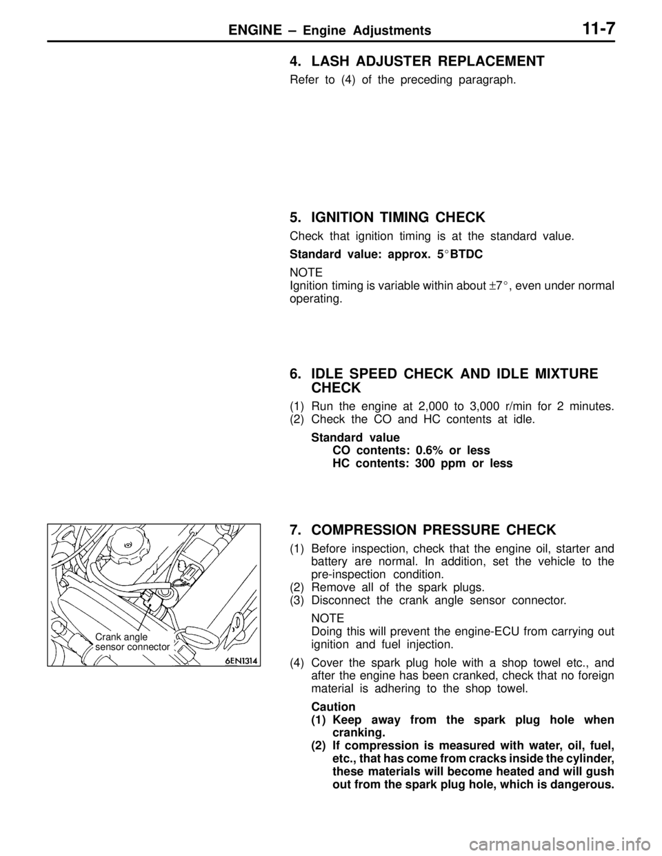
(3) Disconnect the crank angle sensor connector.
NOTE
Doing this will prevent the engine-ECU from carrying out
ignition and fuel injection.
(4) Cover the spark plug hole with a shop towel etc., and
after the engine has been cranked, check that no foreign
material is adhering to the shop towel.
Caution
(1) Keep away from the spark plug hole when
cranking.
(2) If compression is measured with water, oil, fuel,
etc., that has come from cracks inside the cylinder,
these materials will become heated and will gush
out from the spark plug hole, which is dangerous.
Crank angle
sensor connector
Page 18 of 396
ENGINE – Camshaft and Camshaft Oil Seal11-12
�B�CAM CAP / REAR CAP / FRONT CAM CAP
INSTALLATION
(1) Locate the camshaft dowel pins as illustrated.
(2) Temporarily tighten cam cap in two to three steps, then
torque it to specification.
Tightening torque: 20 Nm {2.0 kgf�m}
�C�CAMSHAFT OIL SEAL INSTALLATION
(1) Apply engine oil to the entire periphery of the oil seal
lip.
(2) Pressfit the oil seal as shown.
�D�CAMSHAFT SPROCKET INSTALLATION
As you did during removal, secure the camshaft sprocket
with the special tool and tighten bolt to specification.
Tightening torque: 88 Nm {9.0 kgf�m}
�E�CAM POSITION SENSING CYLINDER
Install the cam position sensing cylinder so that the ID paint
on the cam position sensing cylinder is 90� with respect to
the camshaft dowel pin as shown.
Intake side Approx. 12�Dowel pin
Exhaust side
MD998713
ID paintDowel pin
90�
Page 22 of 396
ENGINE – Crankshaft Oil Seal11-16
REMOVAL SERVICE POINT
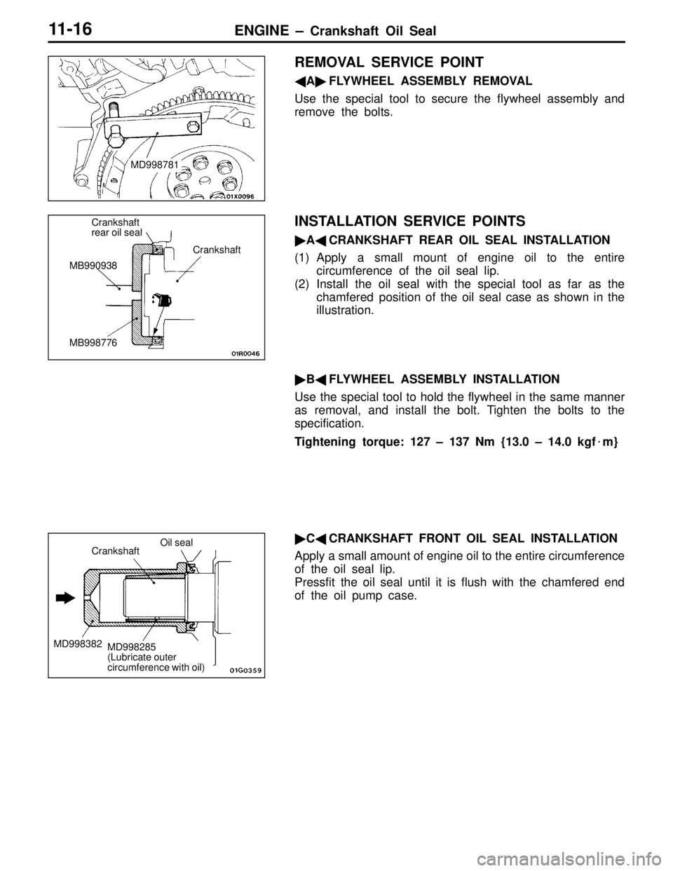
�A�FLYWHEEL ASSEMBLY REMOVAL
Use the special tool to secure the flywheel assembly and
remove the bolts.
INSTALLATION SERVICE POINTS
�A�CRANKSHAFT REAR OIL SEAL INSTALLATION
(1) Apply a small mount of engine oil to the entire
circumference of the oil seal lip.
(2) Install the oil seal with the special tool as far as the
chamfered position of the oil seal case as shown in the
illustration.
�B�FLYWHEEL ASSEMBLY INSTALLATION
Use the special tool to hold the flywheel in the same manner
as removal, and install the bolt. Tighten the bolts to the
specification.
Tightening torque: 127 – 137 Nm {13.0 – 14.0 kgf�m}
�C�CRANKSHAFT FRONT OIL SEAL INSTALLATION
Apply a small amount of engine oil to the entire circumference
of the oil seal lip.
Pressfit the oil seal until it is flush with the chamfered end
of the oil pump case.
MD998781
Crankshaft
rear oil seal
MB990938
MB998776Crankshaft
Crankshaft
MD998382
Oil seal
MD998285
(Lubricate outer
circumference with oil)
Page 33 of 396
ENGINE – T iming Belt 11-27
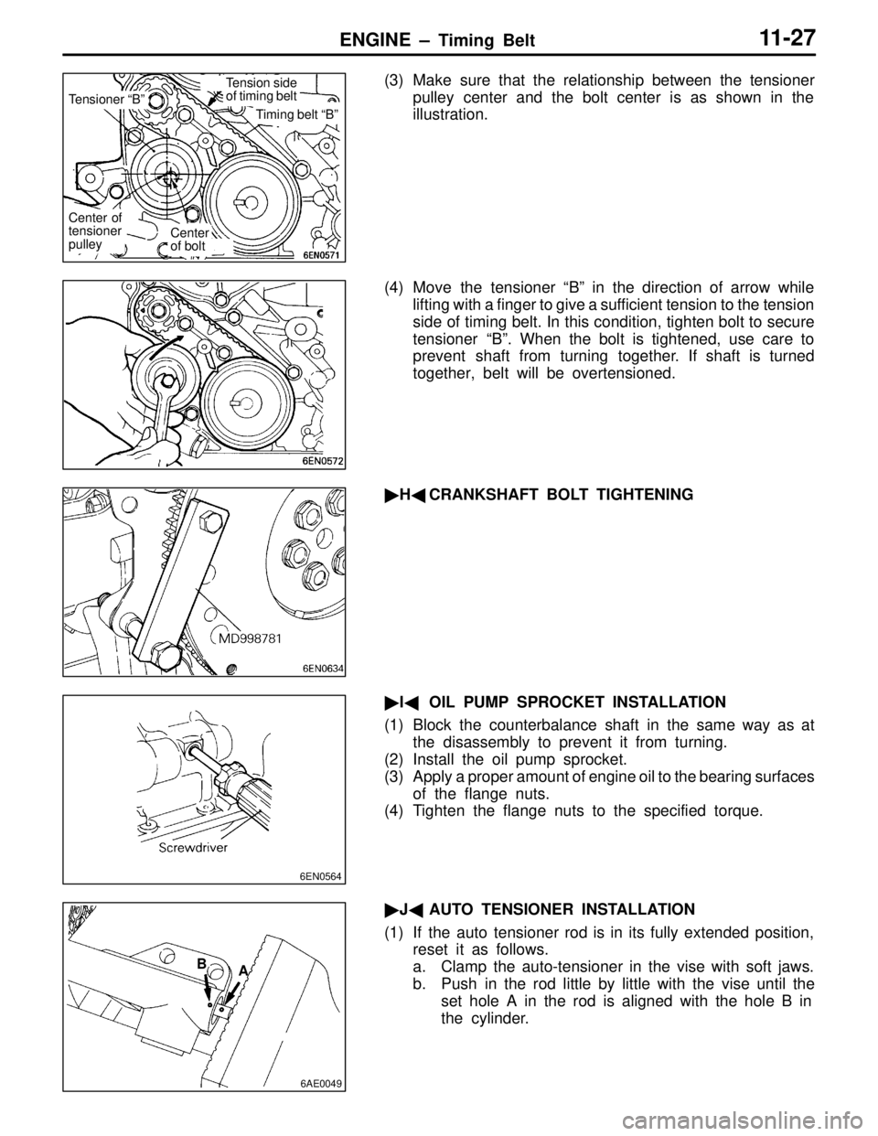
(3) Make sure that the relationship between the tensioner
pulley center and the bolt center is as shown in the
illustration.
(4) Move the tensioner “B” in the direction of arrow while
lifting with a finger to give a sufficient tension to the tension
side of timing belt. In this condition, tighten bolt to secure
tensioner “B” . When the bolt is tightened, use care to
prevent shaft from turning together. If shaft is turned
together, belt will be overtensioned.
� H� CRANKSHAFT BOLT TIGHTENING
� I� OIL PUMP SPROCKET INSTALLATION
(1) Block the counterbalance shaft in the same way as at the disassembly to prevent it from turning.
(2) Install the oil pump sprocket.
(3) Apply a proper amount of engine oil to the bearing surfaces
of the flange nuts.
(4) Tighten the flange nuts to the specified torque.
� J� AUTO TENSIONER INSTALLATION
(1) If the auto tensioner rod is in its fully extended position, reset it as follows.
a. Clamp the auto-tensioner in the vise with soft jaws.
b. Push in the rod little by little with the vise until the
set hole A in the rod is aligned with the hole B in
the cylinder.
Tensioner “B”
Timing belt “B”
Tension side
of timing belt
Center of
tensioner
pulley
Center
of bolt
6EN0564
6AE0049
A
B
Page 35 of 396
ENGINE – T iming Belt 11-29
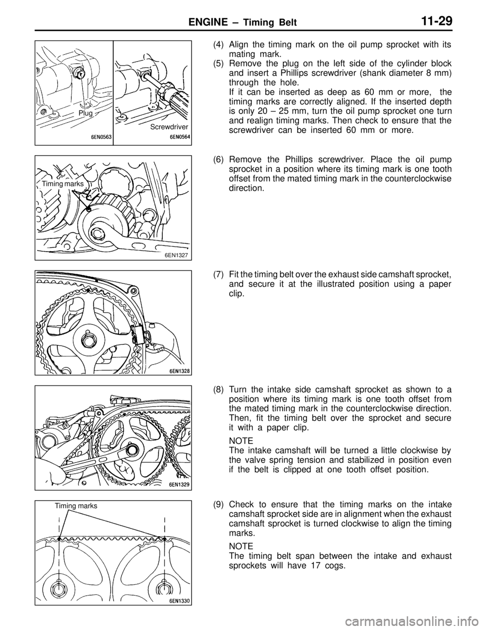
(4) Align the timing mark on the oil pump sprocket with its
mating mark.
(5) Remove the plug on the left side of the cylinder block
and insert a Phillips screwdriver (shank diameter 8 mm)
through the hole.
If it can be inserted as deep as 60 mm or more, the
timing marks are correctly aligned. If the inserted depth
is only 20 – 25 mm, turn the oil pump sprocket one turn
and realign timing marks. Then check to ensure that the
screwdriver can be inserted 60 mm or more.
(6) Remove the Phillips screwdriver. Place the oil pump sprocket in a position where its timing mark is one tooth
offset from the mated timing mark in the counterclockwise
direction.
(7) Fit the timing belt over the exhaust side camshaft sprocket, and secure it at the illustrated position using a paper
clip.
(8) Turn the intake side camshaft sprocket as shown to a position where its timing mark is one tooth offset from
the mated timing mark in the counterclockwise direction.
Then, fit the timing belt over the sprocket and secure
it with a paper clip.
NOTE
The intake camshaft will be turned a little clockwise by
the valve spring tension and stabilized in position even
if the belt is clipped at one tooth offset position.
(9) Check to ensure that the timing marks on the intake camshaft sprocket side are in alignment when the exhaust
camshaft sprocket is turned clockwise to align the timing
marks.
NOTE
The timing belt span between the intake and exhaust
sprockets will have 17 cogs.
Screwdriver
Plug
Timing marks
6EN1327
Timing marks
Page 36 of 396
ENGINE – Timing Belt11-30
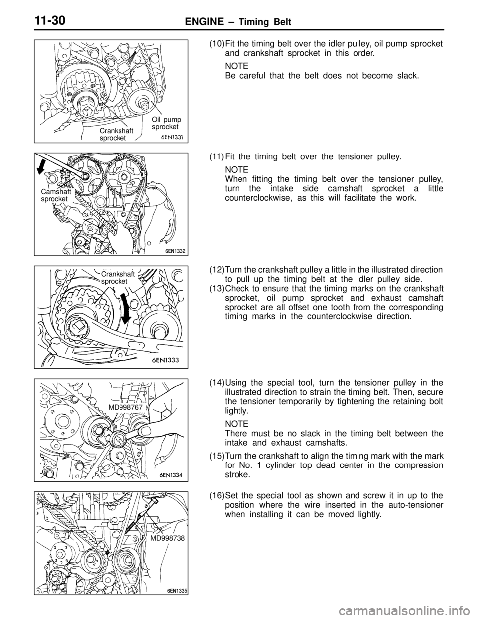
(10)Fit the timing belt over the idler pulley, oil pump sprocket
and crankshaft sprocket in this order.
NOTE
Be careful that the belt does not become slack.
(11) Fit the timing belt over the tensioner pulley. NOTE
When fitting the timing belt over the tensioner pulley,
turn the intake side camshaft sprocket a little
counterclockwise, as this will facilitate the work.
(12)Turn the crankshaft pulley a little in the illustrated direction to pull up the timing belt at the idler pulley side.
(13)Check to ensure that the timing marks on the crankshaft sprocket, oil pump sprocket and exhaust camshaft
sprocket are all offset one tooth from the corresponding
timing marks in the counterclockwise direction.
(14)Using the special tool, turn the tensioner pulley in the illustrated direction to strain the timing belt. Then, secure
the tensioner temporarily by tightening the retaining bolt
lightly.
NOTE
There must be no slack in the timing belt between the
intake and exhaust camshafts.
(15)Turn the crankshaft to align the timing mark with the mark for No. 1 cylinder top dead center in the compression
stroke.
(16)Set the special tool as shown and screw it in up to the position where the wire inserted in the auto-tensioner
when installing it can be moved lightly.
Crankshaft
sprocket Oil pump
sprocket
Camshaft
sprocket
Crankshaft
sprocket
MD998767
MD998738
Page 37 of 396

ENGINE – T iming Belt 11-31
(17)Loosen the retaining bolt of the tensioner pulley.
Caution
Loosening the retaining bolt can cause the intake
and exhaust camshafts to turn, resulting in slackened
timing belt. Use care that the timing belt does not
come off the sprockets at this time.
(18)Pull up the slack of the timing belt by turning the tensioner in illustrated direction using the special tool and a torque
wrench (0 – 5 Nm {0 – 0.5 kgf �m}).
(19)From this position, turn back the tensioner until the torque wrench reading becomes 3.5 Nm {0.36 kgf �m}, then
secure it by tightening the retaining bolt.
(20)Remove the special tool attached in step (16).
(21)Rotate the crankshaft clockwise 2 turns. Then, leave it intact 15 minutes.
(22)Check to see that the wire inserted when installing the
auto-tensioner can be pulled out lightly. If it can be pulled
out lightly, the timing belt is being tensioned properly.
If so, remove the wire. In addition, check that the rod
protrusion from the auto-tensioner meets the standard
value, which is also an indication of properly tensioned
timing belt.
Standard value: 3.8 – 4.5 mm
(23)If the wire cannot be removed with a light force, repeat steps (16) through (21) until the proper belt tensioner
is obtained.MD998767