Page 37 of 396

ENGINE – T iming Belt 11-31
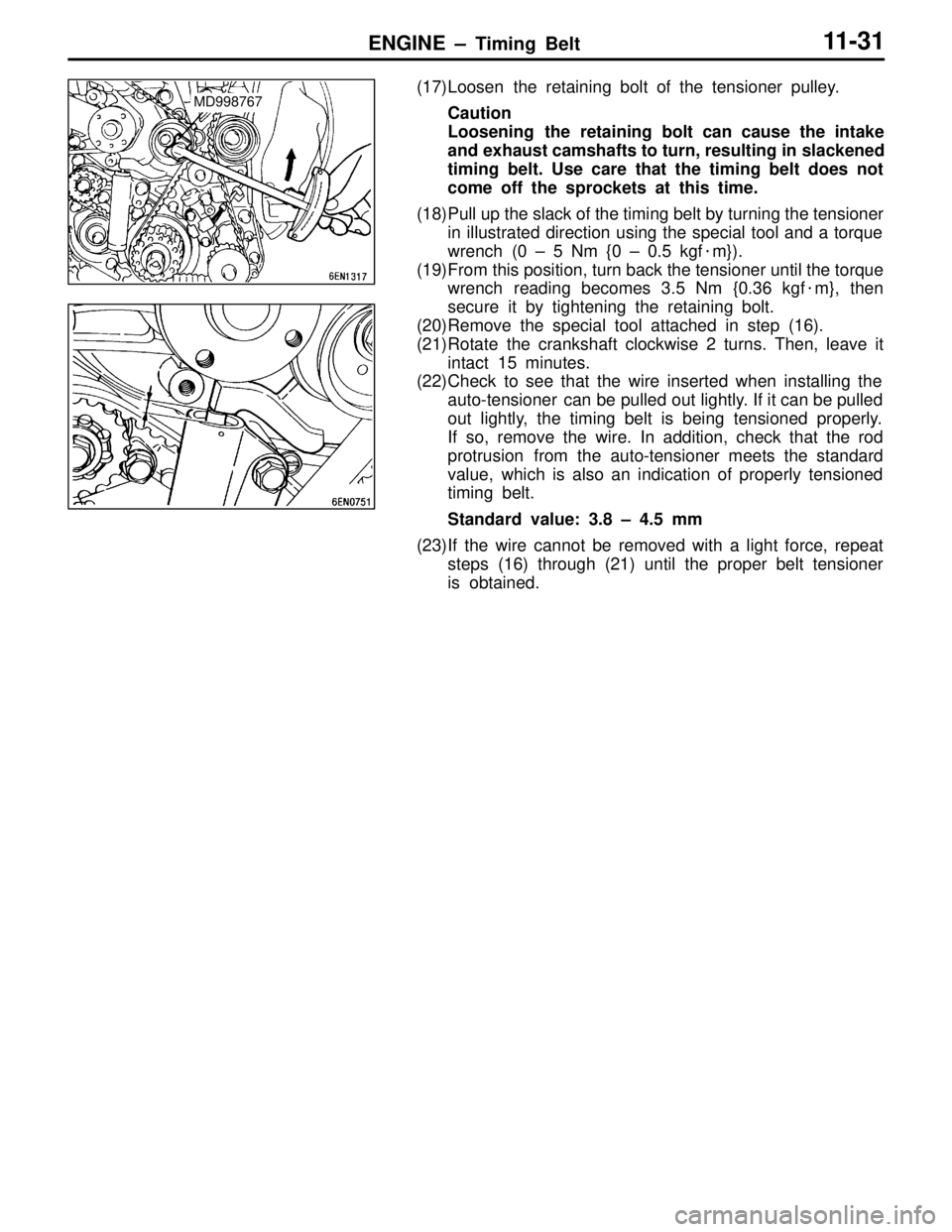
(17)Loosen the retaining bolt of the tensioner pulley.
Caution
Loosening the retaining bolt can cause the intake
and exhaust camshafts to turn, resulting in slackened
timing belt. Use care that the timing belt does not
come off the sprockets at this time.
(18)Pull up the slack of the timing belt by turning the tensioner in illustrated direction using the special tool and a torque
wrench (0 – 5 Nm {0 – 0.5 kgf �m}).
(19)From this position, turn back the tensioner until the torque wrench reading becomes 3.5 Nm {0.36 kgf �m}, then
secure it by tightening the retaining bolt.
(20)Remove the special tool attached in step (16).
(21)Rotate the crankshaft clockwise 2 turns. Then, leave it intact 15 minutes.
(22)Check to see that the wire inserted when installing the
auto-tensioner can be pulled out lightly. If it can be pulled
out lightly, the timing belt is being tensioned properly.
If so, remove the wire. In addition, check that the rod
protrusion from the auto-tensioner meets the standard
value, which is also an indication of properly tensioned
timing belt.
Standard value: 3.8 – 4.5 mm
(23)If the wire cannot be removed with a light force, repeat steps (16) through (21) until the proper belt tensioner
is obtained.MD998767
Page 40 of 396

ENGINE – Engine Assembly 11- 34
REMOVAL SERVICE POINTS
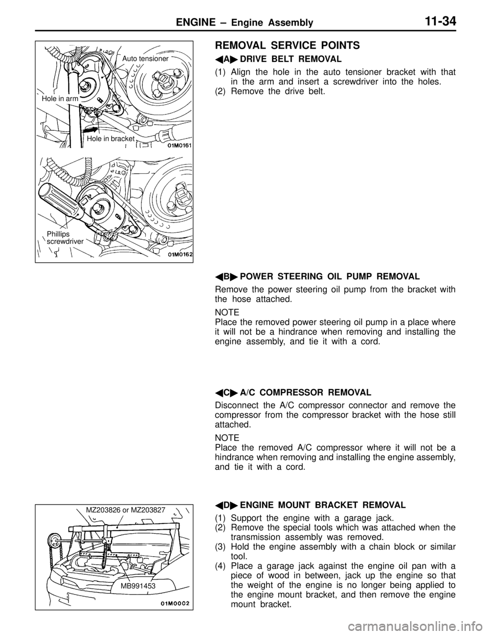
� A� DRIVE BELT REMOVAL
(1) Align the hole in the auto tensioner bracket with that in the arm and insert a screwdriver into the holes.
(2) Remove the drive belt.
� B� POWER STEERING OIL PUMP REMOVAL
Remove the power steering oil pump from the bracket with
the hose attached.
NOTE
Place the removed power steering oil pump in a place where
it will not be a hindrance when removing and installing the
engine assembly, and tie it with a cord.
� C� A/C COMPRESSOR REMOVAL
Disconnect the A/C compressor connector and remove the
compressor from the compressor bracket with the hose still
attached.
NOTE
Place the removed A/C compressor where it will not be a
hindrance when removing and installing the engine assembly,
and tie it with a cord.
� D� ENGINE MOUNT BRACKET REMOVAL
(1) Support the engine with a garage jack.
(2) Remove the special tools which was attached when the transmission assembly was removed.
(3) Hold the engine assembly with a chain block or similar tool.
(4) Place a garage jack against the engine oil pan with a piece of wood in between, jack up the engine so that
the weight of the engine is no longer being applied to
the engine mount bracket, and then remove the engine
mount bracket.
Phillips
screwdriver
Hole in arm
Auto tensioner
Hole in bracket
MZ203826 or MZ203827
MB991453
Page 41 of 396

ENGINE – Engine Assembly11-3 5
�E� ENGINE ASSEMBLY REMOVAL
After checking that all cables, hoses and harness connectors,
etc., are disconnected from the engine, lift the chain block
slowly to remove the engine assembly upward from the engine
compartment.
INSTALLATION SERVICE POINTS
� A� ENGINE ASSEMBLY INSTALLATION
Install the engine assembly, checking that the cables, hoses,
and harness connectors are not clamped.
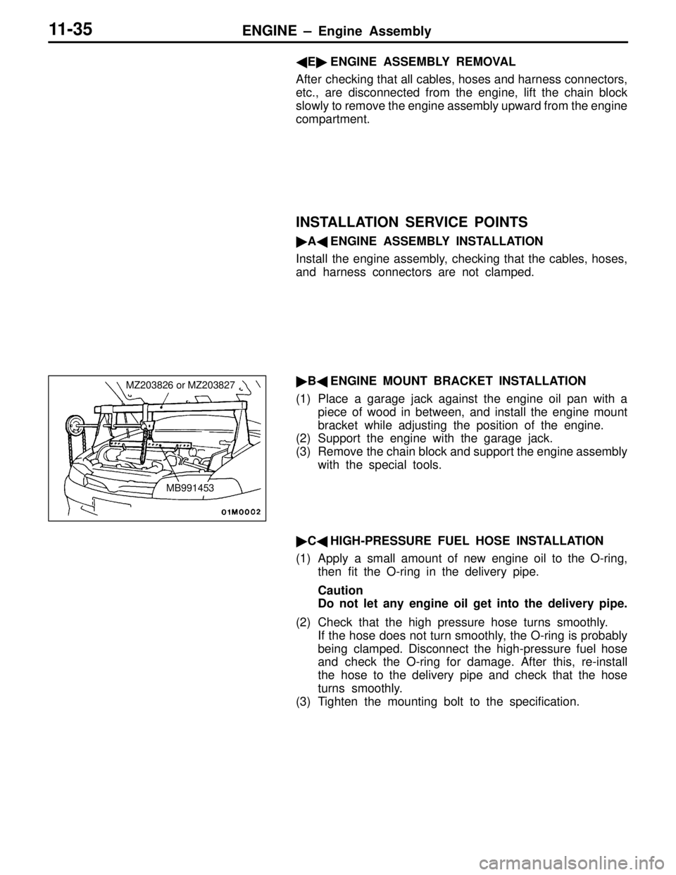
� B� ENGINE MOUNT BRACKET INSTALLATION
(1) Place a garage jack against the engine oil pan with a piece of wood in between, and install the engine mount
bracket while adjusting the position of the engine.
(2) Support the engine with the garage jack.
(3) Remove the chain block and support the engine assembly
with the special tools.
� C� HIGH-PRESSURE FUEL HOSE INSTALLATION
(1) Apply a small amount of new engine oil to the O-ring, then fit the O-ring in the delivery pipe.
Caution
Do not let any engine oil get into the delivery pipe.
(2) Check that the high pressure hose turns smoothly. If the hose does not turn smoothly, the O-ring is probably
being clamped. Disconnect the high-pressure fuel hose
and check the O-ring for damage. After this, re-install
the hose to the delivery pipe and check that the hose
turns smoothly.
(3) Tighten the mounting bolt to the specification.
MZ203826 or MZ203827
MB991453
Page 82 of 396
ENGINE COOLING – Service Specifications / Lubricant / On-vehicle Service14-2
SERVICE SPECIFICATIONS
ItemsStandard value
Thermostat valve opening temperature �CWhen open76.5 ± 1.5
When fully open90
Thermostat lift mm8.5 or more
LUBRICANT
ItemsBrandQuantity dm3 {�}
Coolant capacity (in condenser tank)MITSUBISHI GENUINE DIA QUEEN SUPER
LONG LIFE COOLANT6 {6}
ON-VEHICLE SERVICE
COOLANT REPLACEMENT
CYLINDER BLOCK DRAIN PLUG
Unit: Nm {kgf�m}
Drying sealant: HELMESEAL H-1M
44 {4.5}
RADIATOR CAP VALVE OPENING PRESSURE
CHECK
On EVOLUTION-V, the radiator cap valve opening pressure
must be as shown below.
Standard value: 93 – 123 kPa {0.95 – 1.25 kgf/cm
2}
Limit: 83 kPa {0.85 kgf/cm
2}
Page 92 of 396

INTAKE AND EXHAUST – On-vehicle Service15-3
(3) If the boost pressure is lower than the standard value,
check for following which are probably the cause:
�Wastegate actuator inoperative
�Boost pressure leak
�Turbocharger defective
(4) If the boost pressure is higher than the standard value,
boost pressure control is probably faulty. Make the
following checks:
�Wastegate actuator inoperative
�Wastegate valve inoperative
�Wastegate actuator rubber hose disconnected or
cracked
2. BOOST PRESSURE CONTROL SYSTEM
CHECK
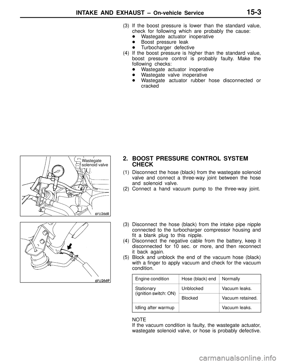
(1) Disconnect the hose (black) from the wastegate solenoid
valve and connect a three-way joint between the hose
and solenoid valve.
(2) Connect a hand vacuum pump to the three-way joint.
(3) Disconnect the hose (black) from the intake pipe nipple
connected to the turbocharger compressor housing and
fit a blank plug to this nipple.
(4) Disconnect the negative cable from the battery, keep it
disconnected for 10 sec. or more, and then reconnect
it back again.
(5) Block and unblock the end of the vacuum hose (black)
with a finger to apply vacuum and check for the vacuum
condition.
Engine conditionHose (black) endNormally
Stationary
(ignition switch: ON)
UnblockedVacuum leaks.
(ignition switch: ON)
BlockedVacuum retained.
Idling after warmupVacuum leaks.
NOTE
If the vacuum condition is faulty, the wastegate actuator,
wastegate solenoid valve, or hose is probably defective.
Wastegate
solenoid valve
Page 103 of 396
INTAKE AND EXHAUST – Exhaust Pipe and Muffler15-14
EXHAUST PIPE AND MUFFLER
REMOVAL AND INSTALLATION
Unit: Nm {kgf�m}
15
44 {4.5}
49 {5.0}
34 {3.5}
5 {0.5}13 {1.3}
14
16
7 5 13
172 1
3
46 18
8
9 12
10 11
34 {3.5}
19 {1.9}49 {5.0}
Hanger mounting bolt tightening
torque
13 {1.3}
3, 9, 18
93 3 9
Main muffler removal steps
1. Bolt
2. Main muffler
3. Hanger
Center exhaust pipe removal steps
1. Bolt
4. Spring
5. Heat protector
6. Self-locking nut
7. Hanger bracket
8. Center exhaust pipe
9. Hanger
10. Protector11. High-temperature sensor
12. Bolt
13. Catalytic converter
14. Front floor heat protector panel
Front exhaust pipe removal steps
4. Spring
5. Heat protector
12. Bolt
15. Self-locking nut
16. Front exhaust pipe
17. Front exhaust pipe bracket
18. Hanger
Page 114 of 396
CLUTCH –
Service Specifications /
Lubricants / On-vehicle Service21-2
SERVICE SPECIFICATIONS
ItemsStandard value
Clutch pedal height mm162.5 – 165.5
Clutch pedal clevis pin play mm1 – 3
Clutch pedal free play mm6 – 13
Distance between the clutch pedal and the toeboard when the clutch is disengaged mm70 or more
LUBRICANTS
ItemsSpecified lubricantsQuantity
Clutch fluidMITSUBISHI genuine brake fluid “DIA-QUEEN
BRAKE FLUID SUPER 4”As required
Push rod assemblyRubber grease
Boot
Release cylinder push rodMOLYKOT BR-2 PUS
ON-VEHICLE SERVICE
1. CLUTCH PEDAL INSPECTION AND
ADJUSTMENT
(1) Turn up the carpet, etc. under the clutch pedal.
(2) Measure the clutch pedal height.
Standard value (A): 162.5 – 165.5 mm
(3) If the height of the clutch pedal is outside the standard
value, loosen the lock nut and adjust the pedal height
to the standard value using the adjusting bolt.
Clutch pedal height
A
Setting nutAdjusting bolt
Locking
nut
13 {1.3}
6 {0.6}
Page 116 of 396
CLUTCH – Clutch Pedal21-4
CLUTCH PEDAL
REMOVAL AND INSTALLATION
Post-installation Operation
�Clutch Pedal Adjustment (Refer to P.21-2.)
(Spring installation position)
13
5
Unit: Nm {kgf�m}
13 {1.3}
1134
11
122
7
6
89 106
3 5
24 {2.4} 13 {1.3}
12 {1.2}
Removal steps
1. Clutch master cylinder installation
nut
2. Master cylinder member bracket
installation bolt
3. Clevis pin
4. Bolt
5. Return spring
6. Bushing7. Pipe
8. Clutch pedal
9. Pedal pad
10. Stopper
11. Adjusting bolt
12. Locking nut
13. Pedal and master cylinder support
member