Page 85 of 396
ENGINE COOLING – Water Pump14-5
WATER PUMP
REMOVAL AND INSTALLATION
Pre-removal and Post-installation Operation
�Engine Coolant Draining and Supplying
(Refer to P.14-2.)�Timing Belt and Timing Belt B Removal and Installation
(Refer to GROUP 11.)
12 – 15 {1.2 – 1.5} 24 {2.4}
8 × 22 8 × 14
Bolt specifications
8 × 24
Screw diameter × length mm
1
2
4
3
2
22 {2.2}
8 × 70
Unit: Nm {kgf�m}
Removal steps
1. Alternator brace
2. Water pump
3. Water pump gasket
�A�4. O-ring
INSTALLATION SERVICE POINT
�A�O-RING INSTALLATION
Fit the O-ring in the O-ring groove in the water inlet pipe,
and coat the outer circumference of the O-ring or the inside
surface of the water pump with water before inserting the
pipe.
Water pump
O-ring
Water inlet pipe
Page 98 of 396

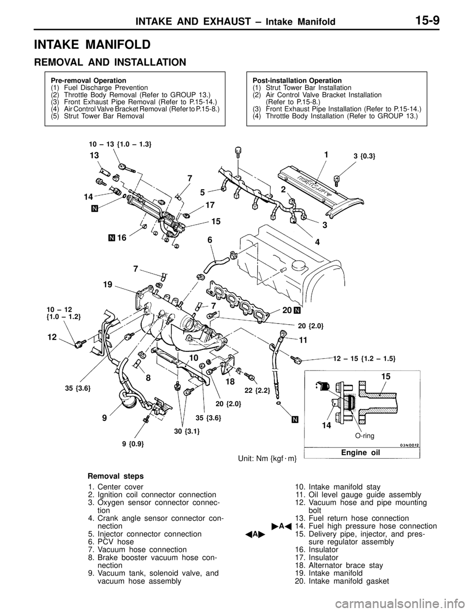
INTAKE AND EXHAUST – Intake Manifold15-9
INTAKE MANIFOLD
REMOVAL AND INSTALLATION
Pre-removal Operation
(1) Fuel Discharge Prevention
(2) Throttle Body Removal (Refer to GROUP 13.)
(3) Front Exhaust Pipe Removal (Refer to P.15-14.)
(4) Air Control Valve Bracket Removal (Refer to P.15-8.)
(5) Strut Tower Bar RemovalPost-installation Operation
(1) Strut Tower Bar Installation
(2) Air Control Valve Bracket Installation
(Refer to P.15-8.)
(3) Front Exhaust Pipe Installation (Refer to P.15-14.)
(4) Throttle Body Installation (Refer to GROUP 13.)
O-ring
Unit: Nm {kgf�m}
15
Engine oil
3 {0.3} 10 – 13 {1.0 – 1.3}
10 – 12
{1.0 – 1.2}
12 – 15 {1.2 – 1.5}
35 {3.6}
9 {0.9}30 {3.1}35 {3.6}20 {2.0}22 {2.2}20 {2.0}
14 14
167
5
17
1521
3
4 6
7 7
19
20
18 8
9 12
1011
13
Removal steps
1. Center cover
2. Ignition coil connector connection
3. Oxygen sensor connector connec-
tion
4. Crank angle sensor connector con-
nection
5. Injector connector connection
6. PCV hose
7. Vacuum hose connection
8. Brake booster vacuum hose con-
nection
9. Vacuum tank, solenoid valve, and
vacuum hose assembly10. Intake manifold stay
11. Oil level gauge guide assembly
12. Vacuum hose and pipe mounting
bolt
13. Fuel return hose connection
�A�14. Fuel high pressure hose connection
�A�15. Delivery pipe, injector, and pres-
sure regulator assembly
16. Insulator
17. Insulator
18. Alternator brace stay
19. Intake manifold
20. Intake manifold gasket
Page 104 of 396
16-1
ENGINE
ELECTRICAL
CONTENTS
CHARGING SYSTEM 2. . . . . . . . . . . . . . . .
ALTERNATOR 2. . . . . . . . . . . . . . . . . . . . . . . . . . .
IGNITION SYSTEM 4. . . . . . . . . . . . . . . . . .
ON-VEHICLE SERVICE 4. . . . . . . . . . . . . . . . . . .
1. Ignition Coil with Built-in Power Transistor
Check 4. . . . . . . . . . . . . . . . . . . . . . . . . . . . . . . .
2. Spark Plug Check, Cleaning, and
Replacement 4. . . . . . . . . . . . . . . . . . . . . . . . . .
CAMSHAFT POSITION SENSOR AND
CRANK ANGLE SENSOR
5 . . . . . . . . . . . . .
Page 105 of 396
ENGINE ELECTRICAL – Charging System16-2
CHARGING SYSTEM
ALTERNATOR
REMOVAL AND INSTALLATION
Pre-removal Operation
(1) Under Cover Removal
(2) Engine Mount Removal
(3) Strut Tower Bar RemovalPost-installation Operation
(1) Strut Tower Bar Installation
(2) Engine Mount Installation
(3) Under Cover Installation
(4) Drive Belt Tension Adjustment
(Refer to GROUP 11 – On-vehicle Service.)
Unit: Nm {kgf�m}
44 {4.5}
7 3
2
6
15 4
24 {2.4} 22 {2.2} 9 {0.9}12 – 15
{1.2 – 1.5}10 – 13
{1.0 – 1.3}
12 {1.2}
Removal steps
�A�1. Drive belt (Power steering, A/C)
�B�2. Delivery pipe, injector and pressure
regulator assembly
3. Oil level gauge guide4. Pressure hose connection
�C�5. Alternator
6. Water pump pulley
7. Alternator brace
Page 106 of 396
ENGINE ELECTRICAL – Charging System16-3
REMOVAL SERVICE POINTS
�A�POWER STEERING, A/C COMPRESSOR, AND
ALTERNATOR DRIVE BELT REMOVAL
(1) Align the hole in the auto tensioner bracket with that
in the arm and insert a screwdriver into the holes.
(2) Remove the drive belt.
�B�DELIVERY PIPE, INJECTOR, AND PRESSURE
REGULATOR ASSEMBLY REMOVAL
After the mounting points have been loosened, slightly move
the corresponding part to allow for a space for removal of
the alternator.
�C�ALTERNATOR REMOVAL
Push the engine all the way up with a garage jack and remove
the alternator upward the engine compartment.
Phillips
screwdriver
Hole in arm
Auto tensioner
Hole in bracket