Page 100 of 188

portion of the system will shut
down to prevent the rear brakes
from overheating. A limited
Traction Controlyfunction using
only engine torque reduction will
still control wheels from
over-spinning. When the rear
brakes have cooled down, the
system will again function
normally. Anti-lock braking is not
affected by this condition and will
function normally during the cool
down period.
If the engine coolant temperature
is below þ23ÉC (þ10ÉF) the engine
torque reduction portion of the
Traction Controlysystem isNOT
active. The system will operate
normally when the engine coolant
warms up.
Traction control switch
The traction control switch is
located on the left side of the
glove compartment. The traction
control system defaults to ON
when the ignition key is turned
from OFF to RUN.
The traction control must be
turned off if you are using a
mini-spare tire in a rear wheel
position.
STEERING
Your vehicle is equipped with
power steering. Power steering
uses energy from the engine to
help steer the vehicle.
Never hold the steering wheel to
the extreme right or the extreme
Driving
101
Page 101 of 188
left for more than a few seconds
when the engine is running. This
action could damage the power
steering pump.
Speed sensitive steering
The steering in your vehicle is
speed sensitive. At high speeds,
steering assist will decrease to
improve steering feel. At lower
speeds, maneuverability will be
increased.
If the amount of effort required to
steer your vehicle changes at a
constant vehicle speed, have the
power steering system checked by
your dealer or a qualified service
technician.
AIR SUSPENSION SYSTEM
The air suspension system is
designed to improve ride, handling
and general vehicle performance
during:
²certain road conditions
²steering maneuvers
²braking
²accelerations
This system keeps the rear of your
vehicle at a constant level by
automatically adding air or
releasing air from the springs.
Driving
102
Page 116 of 188
Passenger compartment fuse
panel
The fuse panel is located below
and to the left of the steering
wheel by the brake pedal. Remove
the panel cover to access the
fuses.
To remove a fuse use the fuse
puller tool provided on the fuse
panel cover.
27 25
26 2423 21
2219
20
18 16
17 1514 12
1310
33
31
2932
30
28 11
97
8653
41
2RELAY
1
Roadside emergencies
117
Page 117 of 188

The fuses are coded as follows.
Fuse/Relay
LocationFuse Amp
RatingDescription
1 10A Lighting Control Module (LCM)
2 30A EATC Blower Motor
3 10A Lighting Control Module (LCM)
4 7.5A Instrument Cluster
5 7.5A Lighting Control Module (LCM)
6 15A EATC, Heated Seats
7 15A Lighting Control Module (LCM),
Day/Night Sensor/Amplifier
8 10A Shift Lock, Speed Control, Air
Suspension, Steering Wheel Rotation
Sensor
9 20A Lighting Control Module (LCM),
Multi-Function Switch
10 20A Brake Pedal Position (BPP) Switch,
Brake Pressure Switch
11 10A Electronic Crash Sensor
12 15A Instrument Cluster, Anti-Theft, Ignition
Switch
13 10A Anti-Lock Brake Module, Traction
Control Switch
14 7.5A Transmission Control Switch, Lighting
Control Module (LCM)
15 20A Multi-Function Switch
16 30A Wiper Control Module (WCM),
Windshield Wiper Motor
17 10A Digital Transmission Range (DTR)
Sensor
18 7.5A Lighting Control Module (LCM), Front
Radio Control Unit, Cellular Telephone
Transceiver, Electronic Day/Night Mirror,
Compass Module
Roadside emergencies
118
Page 121 of 188
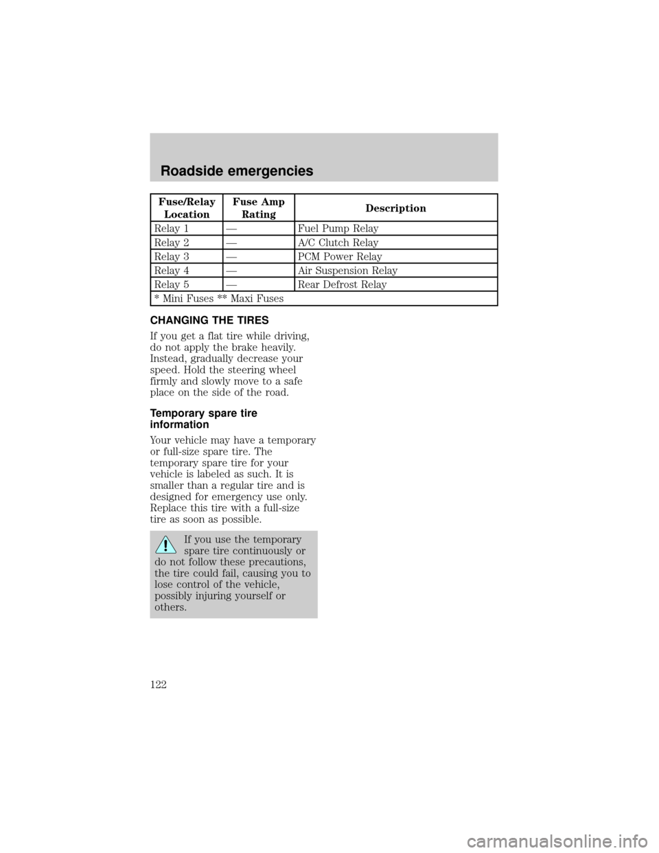
Fuse/Relay
LocationFuse Amp
RatingDescription
Relay 1 Ð Fuel Pump Relay
Relay 2 Ð A/C Clutch Relay
Relay 3 Ð PCM Power Relay
Relay 4 Ð Air Suspension Relay
Relay 5 Ð Rear Defrost Relay
* Mini Fuses ** Maxi Fuses
CHANGING THE TIRES
If you get a flat tire while driving,
do not apply the brake heavily.
Instead, gradually decrease your
speed. Hold the steering wheel
firmly and slowly move to a safe
place on the side of the road.
Temporary spare tire
information
Your vehicle may have a temporary
or full-size spare tire. The
temporary spare tire for your
vehicle is labeled as such. It is
smaller than a regular tire and is
designed for emergency use only.
Replace this tire with a full-size
tire as soon as possible.
If you use the temporary
spare tire continuously or
do not follow these precautions,
the tire could fail, causing you to
lose control of the vehicle,
possibly injuring yourself or
others.
Roadside emergencies
122
Page 133 of 188
IDENTIFYING COMPONENTS IN
THE ENGINE COMPARTMENT
4.6L 2V engine
1. Transmission fluid dipstick
2. Brake fluid reservoir
3. Engine oil fill cap
4. Engine oil dipstick
5. Power steering fluid reservoir
6. Windshield washer fluid
reservoir
7. Air filter assembly
8. Battery
9. Engine coolant reservoir
61234
9578
Maintenance and care
134
Page 144 of 188
²Immediately turn the engine off
to prevent severe engine
damage.
²Wait for the engine to cool.
²Check the coolant level.
CHECKING AND ADDING
POWER STEERING FLUID
Check the power steering fluid at
least twice a year. If adding fluid is
necessary, use only MERCONt
ATF power steering fluid.
1. Start the engine and let it run
until it reaches normal operating
temperature (the engine coolant
temperature gauge will be near the
center of the NORMAL band).
2. While the engine idles, turn the
steering wheel left and right
several times.
3. Turn the engine off.
4. Check the fluid level in the
reservoir. It should be between the
MIN and MAX lines. Do not add
fluid if the level is in this range.
Maintenance and care
145
Page 179 of 188

REFILL CAPACITIES
Fluid Ford Part Name Capacity
Engine oil (includes
filter change)Motorcraft 5W30
Super Premium Motor
Oil4.7L (5.0 quarts)
Brake fluid Ford High
Performance DOT 3
Brake FluidFill to line in reservoir
Power steering fluid Motorcraft MERCONt
AT FFill to line in reservoir
Transmission fluid Motorcraft
MERCONtVATF13.1L (13.9 quarts)
Engine coolant Ford Premium Cooling
System Fluid13.3L (14.1 quarts)
Fuel tank N/A 71.9L (19.0 gallons)
Rear axle fluid
1Motorcraft SAE 80W90
Rear Axle Lubricant1.8-1.9L (3.75-4.0
pints)
Windshield washer
fluidUltra-Clear Windshield
ConcentrateFill to line in reservoir
1Add 118 ml (4 oz.) of additive
friction modifier C8AZ-19B546±A,
Ford specification EST-M2C118±A
for complete refill of Traction-Lok
axles.
Service refill capacities are
determined by filling the rear axle
6 mm to 14 mm (1/4 inch to 9/16
inch) below the bottom of the filler
hole.
Rear axles are considered
lubricated for life when the vehicle
is used for normal service. See
your ªService Guideº for Severe
Duty requirements.
Capacities and specifications
180