Page 27 of 176

INSTRUMENT PANEL DIMMER CONTROL
Use to adjust the brightness of the instrument
panel during headlight and parklamp operation.
²Push up to brighten.
²Push down to dim.
AUTOLAMP CONTROL
The autolamp system provides light
sensitive automatic on-off control of
the exterior lights normally
controlled by the headlamp control.
The autolamp system also keeps the
lights on for a preselected period of
time after the ignition switch is
turned to OFF.
²To turn autolamps on, push the
control up toward the MAX position. As you press this switch, the
autolamp system's status will be displayed in the message center. The
system can be set to provide light for up to three minutes after you
turn the ignition OFF.
²To turn autolamps off, push the control down toward OFF.
CLIMATE CONTROL SYSTEM
Electronic Automatic Temperature Control (EATC) system
The EATC system will maintain a
selected temperature and
automatically control airflow. You
can override automatic operation
with any of the override controls,
the fan speed control or the steering
wheel controls (if equipped).
Turning the EATC on
Press AUTO, any of the override
controls or the fan speed control.
The EATC will only operate when
the ignition is in the ON position.
PANEL
DIM
MAX
OFF
AUTO
LAMP
˚F
AUTO
EXT OFF AUTOMAX
A/CFRONT
REAR
˚F
AUTO
EXT OFF AUTOMAX
A/CFRONT
REAR
Controls and features
27
Page 28 of 176

Turning the EATC off
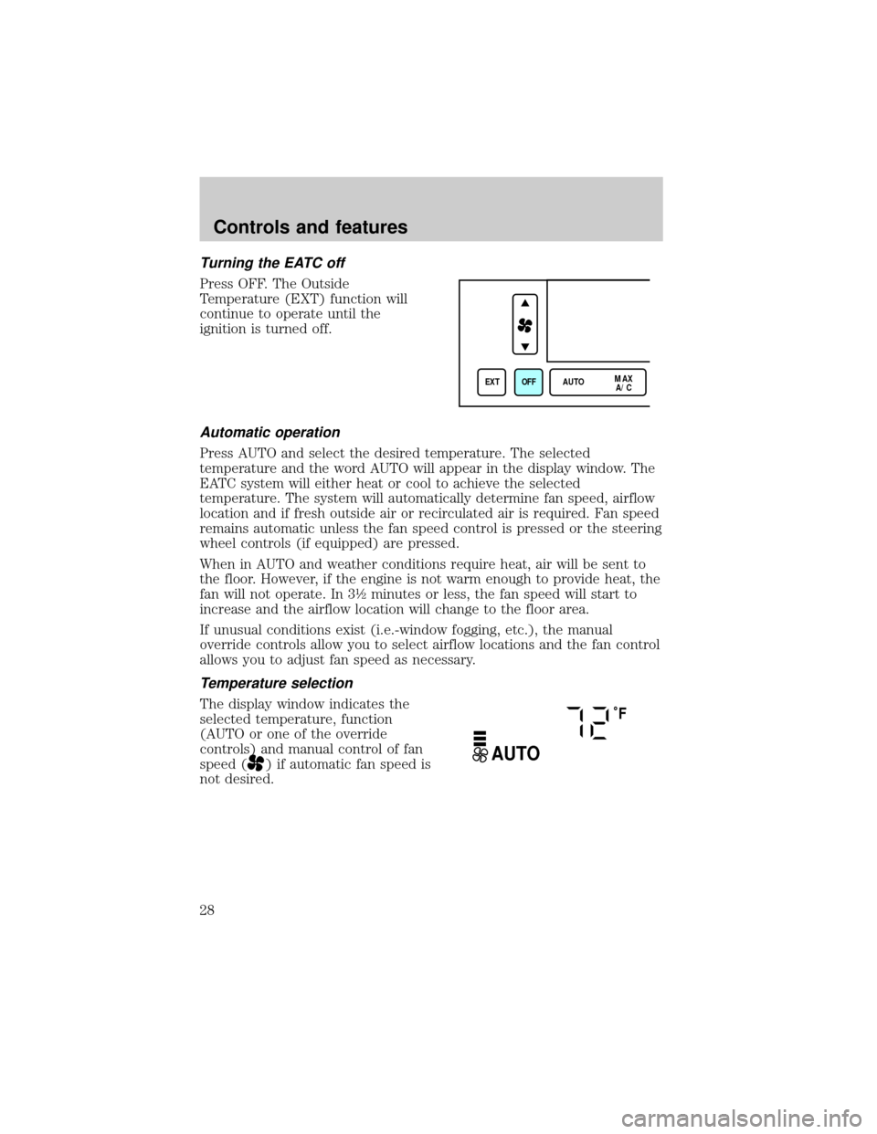
Press OFF. The Outside
Temperature (EXT) function will
continue to operate until the
ignition is turned off.
Automatic operation
Press AUTO and select the desired temperature. The selected
temperature and the word AUTO will appear in the display window. The
EATC system will either heat or cool to achieve the selected
temperature. The system will automatically determine fan speed, airflow
location and if fresh outside air or recirculated air is required. Fan speed
remains automatic unless the fan speed control is pressed or the steering
wheel controls (if equipped) are pressed.
When in AUTO and weather conditions require heat, air will be sent to
the floor. However, if the engine is not warm enough to provide heat, the
fan will not operate. In 3ó minutes or less, the fan speed will start to
increase and the airflow location will change to the floor area.
If unusual conditions exist (i.e.-window fogging, etc.), the manual
override controls allow you to select airflow locations and the fan control
allows you to adjust fan speed as necessary.
Temperature selection
The display window indicates the
selected temperature, function
(AUTO or one of the override
controls) and manual control of fan
speed (
) if automatic fan speed is
not desired.
EXT OFF AUTOMAX
A/C
˚F
AUTO
Controls and features
28
Page 33 of 176
The rear defroster control is located
on the instrument panel.
Press the defroster control to clear
the rear window of thin ice and fog.
²The small LED will illuminate
when the defroster is activated.
The ignition must be in the ON position to operate the rear window
defroster.
The defroster turns off automatically after 10 minutes or when the
ignition is turned to the OFF position. To manually turn off the defroster
before ten minutes have passed, push the control again.
CLOCK (IF EQUIPPED)
Press + to increase the time
displayed.
Press ± to decrease the time
displayed.
AUDIO SYSTEM
Refer to the ªAudio Guideº for instructions on how to operate the audio
system.
FRONT
REAR
NI
T
N
O
CL
A
T
N
E
NI
T
N
O
CL
A
T
N
E
Controls and features
33
Page 34 of 176

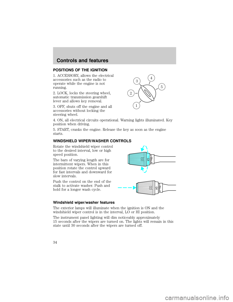
POSITIONS OF THE IGNITION
1. ACCESSORY, allows the electrical
accessories such as the radio to
operate while the engine is not
running.
2. LOCK, locks the steering wheel,
automatic transmission gearshift
lever and allows key removal.
3. OFF, shuts off the engine and all
accessories without locking the
steering wheel.
4. ON, all electrical circuits operational. Warning lights illuminated. Key
position when driving.
5. START, cranks the engine. Release the key as soon as the engine
starts.
WINDSHIELD WIPER/WASHER CONTROLS
Rotate the windshield wiper control
to the desired interval, low or high
speed position.
The bars of varying length are for
intermittent wipers. When in this
position rotate the control upward
for fast intervals and downward for
slow intervals.
Push the control on the end of the
stalk to activate washer. Push and
hold for a longer wash cycle.
Windshield wiper/washer features
The exterior lamps will illuminate when the ignition is ON and the
windshield wiper control is in the interval, LO or HI position.
The instrument panel lighting will dim noticeably approximately
15 seconds after the wipers are turned on. The lights will remain in this
state until 30 seconds after the wipers are turned off.
3
1
2
5
4
OFFHI
LO
OFFHI
LO
Controls and features
34
Page 37 of 176

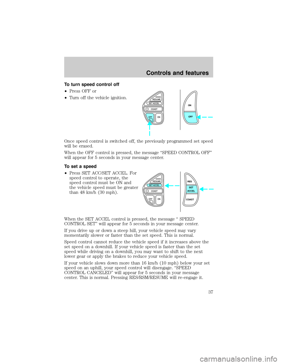
To turn speed control off
²Press OFF or
²Turn off the vehicle ignition.
Once speed control is switched off, the previously programmed set speed
will be erased.
When the OFF control is pressed, the message ªSPEED CONTROL OFFº
will appear for 5 seconds in your message center.
To set a speed
²Press SET ACC/SET ACCEL. For
speed control to operate, the
speed control must be ON and
the vehicle speed must be greater
than 48 km/h (30 mph).
When the SET ACCEL control is pressed, the message ª SPEED
CONTROL SETº will appear for 5 seconds in your message center.
If you drive up or down a steep hill, your vehicle speed may vary
momentarily slower or faster than the set speed. This is normal.
Speed control cannot reduce the vehicle speed if it increases above the
set speed on a downhill. If your vehicle speed is faster than the set
speed while driving on a downhill, you may want to shift to the next
lower gear or apply the brakes to reduce your vehicle speed.
If your vehicle slows down more than 16 km/h (10 mph) below your set
speed on an uphill, your speed control will disengage. ªSPEED
CONTROL CANCELEDº will appear for 5 seconds in your message
center. This is normal. Pressing RES/RSM/RESUME will re-engage it.
ON
OFF
RES
SET
ACCEL
COAST
Controls and features
37
Page 41 of 176

Rear courtesy/reading lamps
The courtesy lamp lights when:
²any door is opened.
²when the instrument panel
dimmer switch is turned to the
courtesy lamp position.
²if any of the keyless entry keypad
controls are pressed and the
ignition is OFF.
With the ignition key in the ACC or ON position, the reading lamp can be
turned on by pressing the rocker control.
LINCOLN RESCU SYSTEM (IF EQUIPPED)
Lincoln RESCU runs a self-test
when you start your vehicle. During
this test, the Lincoln RESCU
warning light (located in the
overhead console) will illuminate
briefly. If a problem is detected
during the self-check, the light will
remain lit and the message ªRESCU
FAILUREº will be displayed on the
vehicle's message center for several
seconds.
If the warning light fails to briefly
illuminate when you start your
vehicle, or if it remains lit, have
your Lincoln RESCU System
checked by an authorized dealer as
soon as possible. Your system may be inoperative.
It is important that you understand the limitations of your
Lincoln RESCU System prior to initiating an activation. See
Lincoln RESCU System Limitationslater in this chapter for details.
The RESCU system can be activated in three ways:
S.O.S.INFO
S.O.S.INFO
i
i
S.O.S.
INFO
i
Controls and features
41
Page 45 of 176

Activation and deactivation
When either of the two Lincoln RESCU controls are pressed, or the air
bags are deployed (this will activate the system as an emergency
automatically), a warning light, located in the overhead console, will
begin to flash and status messages will be displayed on the vehicle's
message center, confirming an assistance request has been made. The
warning light will continue to flash throughout the activation.
The system can be activated whenever your ignition key is in the
RUN/START position and for six minutes after your vehicle is turned off.
Once a RESCU control has been pressed, do not attempt to cranks the
engine as this may cancel the activation. In most situations, the
assistance request can only be terminated and the system reset when a
special tone is sent to the vehicle by the Lincoln Security Response
Center. (SeeAutomatic rediallater in this chapter for exceptions.)
Operation will continue even if the vehicle is turned off during an
activation (although visual feedback via the message center will not be
available in this situation).
Cellular phone interface
The cellular phone must be connected to the vehicle and activated for
the system to work. During an activation, Lincoln RESCU takes control
of the vehicle's cellular phone. If the phone is in use, the call will be
terminated and the Lincoln Security Response Center will automatically
be dialed. The cellular handset becomes inoperative and all voice
communication with the operator is accomplished via the cellular phone's
ªhands-freeº microphone.
When an activation is terminated, your phone is left unlocked, in the ON
state and may not return to its previous call restriction or system
selection setting. It can be reprogrammed to your previous setting as
desired.
Refer to your cellular phone user's manual for further information.
Message center interface
During an activation, Lincoln RESCU communication with the vehicle's
message center. Status message describing the sequence of the steps
being executed are displayed, allowing you to visually follow the
activation process. The following messages are typical of those displayed
during an assistance request. They are as shown in the order in which
they would appear:
Controls and features
45
Page 56 of 176
calibration may be necessary. Refer toCompass calibration
adjustment.
Most geographic areas (zones) have a magnetic north compass point that
varies slightly from the northerly direction on maps. This variation is four
degrees between adjacent zones and will become noticeable as the
vehicle crosses multiple zones. A correct zone setting will eliminate this
error. Refer toCompass zone adjustment.
Compass zone adjustment
1. Determine which magnetic zone
you are in for your geographic
location by referring to the zone
map.
2. Locate the compass module
mounted at the base of mirror.
3. Turn the ignition to the ON
position.
4. Insert an appropriate diameter
rod (paperclip) into the right switch
access hole underneath the compass
module and gently press for 1 to 2
seconds until ZONE and the current
zone setting are displayed on the
upper right corner of the mirror.
1
2
3
4
5
6
7891011121314 15
Controls and features
56