1998 JAGUAR X308 timing chain tensioner
[x] Cancel search: timing chain tensionerPage 10 of 2490

Flexplate
Vehicles With
out:
Supercharger (12.53.13)
Flexplate
Vehicles With: Supercharger (12.53.13)
Intake
Camshaft LH (12.13.16)
Intake
Camshaft RH (12.13.14)
Intake
Manifo
ld (30.15.01)
Intake
Manifold Gaskets (30.15.08)
Intake
Manifold LH (18.50.26)
Intake
Manifold RH (18.50.25)
Intake
Manifold Gasket LH (18.50.28)
Intake
Manifold Gasket RH (18.50.27)
Oil
Pan (12.60.44)
Oil
Pan Gasket (12.60.38)
Oil
Pressure Switch (88.25.07)
Oil
Pump Vehicles Without: Supercharger (12.60.26)
Oil
Pump Vehicles With: Supercharger (12.60.26)
Primary
Timing Chain LH 4.0L, Vehicles Wit
hout: Supercharger (12.65.67)
Primary
Timing Chain LH 3.2L/4.0L, Vehicles With: Supercharger (12.65.67)
Primary
Timing Chain RH (12.65.66)
Primary
Timing Chain Inner Guide LH (12.65.58)
Primary
Timing Chain Inner Guide RH (12.65.60)
Primary
Timing Chain Outer Guide LH (12.65.61)
Primary
Timing Chain Outer Gu
ide RH (12.65.57)
Primary
Timing Chain Tensioner LH (12.65.55)
Primary
Timing Chain Tensioner RH (12.65.54)
Secondary
Timing Chain LH (12.65.69)
Secondary
Timing Chain RH (12.65.68)
Secondary
Timing Chain Tensioner LH 4.0L, Vehicles Without: Supercharger
(12.65.64)
Secondary
Timing Chain Tensioner LH 3.2L/4.0L, Vehicles With: Supercharger
(12.65.64)
Secondar
y Timing Chain Tensioner RH 4.0L, Vehicles Without: Supercharger
(12.65.63)
Secondar y Timing Ch
ain
Tensioner RH 3.2L/4.0L, Vehicles With: Supercharger
(12.65.63)
Upper Oil Pan 3.2L (12.60.48)
Upper Oil Pan 4.0L, Vehicles Without: Supercharger (12.60.48)
Upper Oil Pan 4.0L, Vehicles With: Supercharger (12.60.48)
Page 530 of 2490
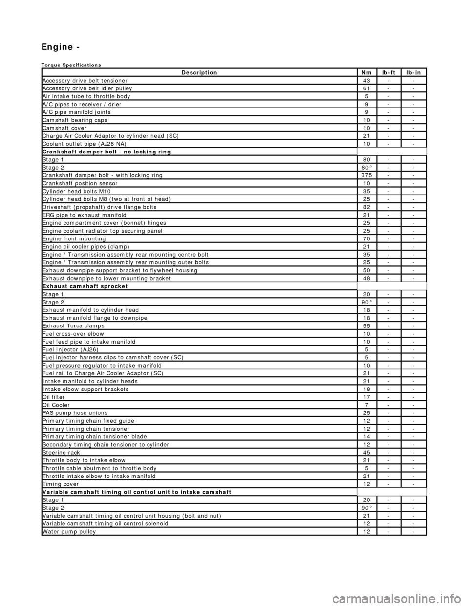
Engi
ne -
Torqu
e Specifications
De
s
cription
Nmlb
-
ft
lb
-
in
A
ccessory
drive belt tensioner
43--
A
ccessory
drive belt idler pulley
61--
Air in
ta
ke tube to throttle body
5--
A/C
pipes t
o receiver / drier
9--
A/C pipe m
anifold joints
9--
Camsh
aft bearin
g caps10--
Ca
msh
aft cove
r10--
Ch
arge Air Co
oler Adaptor to cylinder head (SC)
21--
Co
olan
t outlet pipe (AJ26 NA)
10--
Cran
kshaft damper bolt - no lockin
g ring
St
ag
e 1
80--
Stag
e 2
80°--
C
r
ankshaft damper bolt - with locking ring
37
5--
Cra
nkshaft position sensor
10--
Cy
li
nder head bolts M10
35--
Cy
lin
der head bolts M8 (two at front of head)
25--
Driv
es
haft (propshaft) drive flan
ge bo
l
ts
82--
ERG p
i
pe to exhaust manifold
21--
Engi
ne compartment cover (bonnet) hinges
25--
En
gine
coolant radiator top securing panel
25--
E
ng
ine front mounting
70--
En
gine
oil cooler pipes (clamp)
21--
En
gi
ne / Transmission assembly rear mounting centre bolt
35--
En
gi
ne / Transmission assembly rear mounting outer bolts
25--
Ex
ha
ust downpipe support bracket to flywheel housing
50--
Ex
ha
ust downpipe to lower mounting bracket
48--
E
x
haust camshaft sprocket
St
age 120--
Stage 290 °--
Ex
haust manifold to cylinder head
18--
Ex
ha
ust manifold flange to downpipe
18--
E
x
haust Torca clamps
55--
Fuel cross-over elbo
w
10--
Fu
el f
eed pipe to intake manifold
10--
Fuel
Injector (AJ
26)
5--
Fuel
injector ha
rness clips to camshaft cover (SC)
5--
Fu
el p
ressure re
gu
l
ator to intake manifold
10--
F
u
el rail to Char
ge
A
ir Cooler Adaptor (SC)
21--
In
ta
ke manifold to cylinder heads
21--
Inta
ke elbow support brackets
18--
Oil f
i
lter
17--
Oil C
o
oler
7--
P
AS pu
mp hose unions
25--
P
r
imary timing chain fixed guide
12--
P
r
imary timing chain tensioner
12--
Pr
imary timing chain tensioner blade
14--
S
e
condary timing chain tensioner to cylinder
12--
S
t
eerin
g ra
ck45--
Thro
ttle body to intake elbow
21--
Th
ro
ttle cable abutment to throttle body
5--
Th
ro
ttle intake elbow to intake manifold
21--
Ti
mi
ng cover
12--
Variable camshaft t
i
ming oil control unit to intake camshaft
St
ag
e 1
20--
St
ag
e 2
90
°--
Var
iable camshaft timing oil control unit housing (bolt and nut)
21--
Va
ria
ble camshaft timi
ng oil control solenoid
12--
Wa
ter pump pulley
12--
Page 571 of 2490

I
nstallation
32
.
Clean and inspect all relevant components.
1. F
it the sprockets to the crankshaft.
Th
e teeth of the A-Bank and the B-Bank sprockets on the
crankshaft must be out of phas e with each other. If they
are in-phase after fitting, remove the A-Bank sprocket,
turn it on its vertical axis and refit it.
2. F
it the chain tensioning tool 303 - 532 to the exhaust camshaft
sprocket, B-Bank.
Re
position the sprocket (and
the VVT unit) for the most
advantageous position for use of the tool.
R
emove the tool.
3. R
efit the primary timing chain, B-Bank.
1. Fit the primary chain over the crankshaft sprocket and the VVT unit sprocket. There must be no slack on
the drive side of the primary chain and the VVT unit
must not be rotate d on the camshaft.
Sl
ide the VVT and exhaust sprocket fully rearwards onto
the respective camshafts.
4. Fit the primary chain tensioner blade.
1. Position the tensioner blade to the cylinder block.
Page 573 of 2490

9. F
it the chain tensioning tool 303 - 532 to the exhaust camshaft
sprocket, A-Bank.
Re
position the sprocket (and
the VVT unit) for the most
advantageous position for use of the tool.
R
emove the tool.
10
.
Refit the primary timing chain, A-Bank.
1. Fit the primary chain over the crankshaft sprocket and the VVT unit sprocket. There must be no slack on
the drive side of the primary chain and the VVT unit
must not be rotate d on the camshaft.
11
.
Fit the primary chain tensioner blade.
1. Position the tensioner blade to the cylinder block.
2. Fit the retaining / pivot bolt and tighten it to 12 - 16 Nm.
12. Refit the primary chain tens ioner assembly. Refer to
Operation 12.65.54 in this Section.
U
se a wedge 303 - 533 (or two if required) between the
primary chain tensioner and te nsioner blade, to take up
the slack in the chain.
Page 584 of 2490

13. Tigh
ten the exhaust camshaft
sprocket securing bolt.
1. Install the chain tensioner tool 303-532 to the sprocket holes.
Appl y force
to the tool in an
anti-clockwise direction to
tension the chain on its drive side.
2. Whilst applying the opposing force to the sprocket and chain, tighten the sprock et securing bolt to 115-
125 Nm.
14 .
Tigh
ten the intake camshaft
sprocket securing bolt.
1. Whilst still applying the opposing force to the
sprocket and chain (using 303-532), check that the
wedges are still in place, ti ghten the securing bolt to
115-125 Nm.
R e
move the chain tensioning
tool and the wedge(s).
15. Remove the camshaft locking tool 303-530.
16. Raise the vehicle on the ramp.
17. Remove the crankshaft setting tool 303-531.
18 . Inst
all the crankshaft position sensor.
1. Install the sensor to the flywheel housing and install
the securing bolt. Tighten to 6-8 Nm.
2. Install the access grommet to the housing.
19. Lower the ramp.
20. Install the Timing Cover. Refer to Operation 12.65.01.
21. Move the engine compartment cover from the service position
and connect the gas struts.
22. Remove the paint protection sheets and close the cover.
Page 590 of 2490

The
teeth of the A-Bank and the B-Bank sprockets on the
crankshaft must be out of phas e with each other. If they
are in-phase after fitting, remo ve the sprocket, turn it on
its vertical axis and refit it.
2. Fi
t the chain tensioning tool 303 - 532 to the exhaust camshaft
sprocket.
Re po
sition the sprocket (and
the VVT unit) for the most
advantageous position for use of the tool.
R e
move the tool.
3. Re
fit the primary timing chain.
1. Fit the primary chain to position over the crankshaft sprocket and the VVT unit sprocket. There must be no
slack on the drive side of the primary chain and the
VVT unit must not be rotated on the camshaft.
4. Fit the primary chain tensioner
blade.
1. Position the tensioner blade to the cylinder block.
2. Fit the retaining / pivot bolt and tighten it to 12-16 Nm.
5. Refit the primary chain tensione r assembly. Refer to Operation
12.65.54 in this Section.
U s
e a wedge 303 - 533 (or two if required) between the
primary chain tensioner and te nsioner blade, to take up
the slack in the chain.
Page 623 of 2490

Re
position the sprocket (and the VVT unit) for the most advantageous
position for use of the tool.
R
emove the tool.
25
.
Install the primary timing chain.
R
eposition the VVT unit forwards on the cam journal (do not rotate it)
to allow the chain to cl ear the head casting. Disconnect the primary
chain from the Ty-strap.
1. Install the primary chain to position over the crankshaft sprocket and the VVT unit sprocket. There mu st be no slack on the drive
side of the primary chain and the VVT unit must not be rotated on
the camshaft.
26
.
Install the primary chain tensioner blade.
1. Position the tensioner blade to the cylinder block.
2. Install the retaining / pivot bolt and tighten it to 14 Nm.
27
.
Push the primary chain tensioner piston into the body to provide clearance
for installing.
1. Insert a thin rigid wire through the hole in the end of the tensioner
piston to displace the ball from the non-return valve seat.
2. With the wire in position, press the piston fully into the tensioner body.
Re
move the wire.
28
.
Assemble the tensioner.
1. Install the two mounting bolts to the tensioner.
2. Locate the tensioner back-plate to the two bolts.
29. Install the tensioner to the cylinder block.
1. Position and align the tensioner to the cylinder block and to the mating slot on the rear face of the tensioner blade.
2. Install and tighten the two bolts to 12 Nm.
Page 637 of 2490

To th
e upper face of each bearing surface (two places) in the cylinder
head.
To th
e upper face of each bearing surface (two places) in each bearing
cap.
On
the cam lobes ONLY, not on the base circle area.
17
.
Install the camshafts.
1. Install the camshafts to position in the cylinder head, with the timing flats uppermost.
2. Install the camshaft caps to their respective locations (inlet 0 to 4 and exhaust 5 to 9 from the front) and in the correct orientation
(arrow to front of engine).
3. Install and tighten the cap securing bolts. Tighten evenly, in stages, to 10 Nm.
18. Install the camshaft locking tool 303 - 530, align the camshafts as
necessary.
19
.
Install the chain guide.
• NOTE: The chain guide must be installed so that the slotted hole is
towards the top, and the raised shoulder to the cylinder block. 1. Install the chain guide to the block and locate it onto the upper retaining pin.
2. Install the retaining bolt and tighten it to 12 Nm.
20
.
Push the secondary chain tensioner piston into the body to provide
clearance for installing the chain.
1. Insert a thin rigid wire through the hole in the end of the tensioner
piston to displace the ball from the non-return valve seat.
2. With the wire in position, press the piston fully into the tensioner body.
Re
move the wire.
21
.
Install the secondary chain tensioner to the engine.
1. Fully seat the tensioner to the cylinder head.
2. Install the two bolts which secure the tensioner and tighten to 12 Nm.
22. Install the VVT unit to the engine.
A
ssemble the VVT unit, the exhaust camshaft sprocket and the