Page 1513 of 2490
Automatic Transmission/Transaxle External Contro ls - 4.0L SC V8 - AJ26 -
Selector Lever Cable and Bracket
Removal and Installation
Removal
1. Disconnect the vehicle battery ground lead.
2. Position the selector to N.
3. Remove the J-gate surround, Section 501-05.
4. Remove the console finisher ve neer panel, Section 501-12.
5. Remove the center console assembly, Section 501-12.
6. Raise the vehicle for access.
7. Detach the gear selector cable from the transmission unit.
1. Remove the nut which secures the selector cable ball pin to the selector lever.
2. Lower the transmissi on lift for access.
3. Remove the bolts which secure the selector cable to the transmission casing.
8. Reposition the selector cable.
9. Remove the LH front seat, Section 501-10.
10. Reposition the LH floo r carpet for access.
11. Remove the selector cable to tunnel clip tie strap.
12. Detach the selector cable from the gear shift assembly.
1. Remove the inner cable to shift lever nut.
Page 1515 of 2490
3. Secure the outer cable.
4. Adjust the selector cable in accordance with Operation
44.15.07.
5. Further installation is the reve rse of the removal procedure.
Page 1518 of 2490

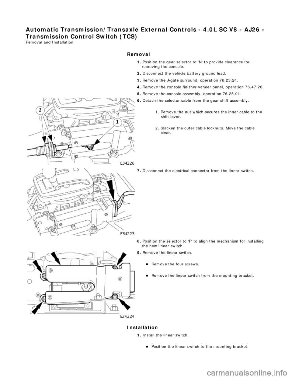
Automatic Transmission/Transaxle External Contro ls - 4.0L SC V8 - AJ26 -
Transmission Control Switch (TCS)
Removal and Installation
Removal
Installation
1. Position the gear selector to 'N' to provide clearance for
removing the console.
2. Disconnect the vehicle battery ground lead.
3. Remove the J-gate surroun d, operation 76.25.24.
4. Remove the console finisher vene er panel, operation 76.47.26.
5. Remove the console assembly, operation 76.25.01.
6. Detach the selector cable from the gear shift assembly.
1. Remove the nut which secures the inner cable to the shift lever.
2. Slacken the outer cable locknuts. Move the cable clear.
7. Disconnect the electrical conne ctor from the linear switch.
8. Position the selector to 'P' to align the mechanism for installing
the new linear switch.
9. Remove the linear switch.
Remove the four screws.
Remove the linear switch fro m the mounting bracket.
1. Install the linear switch.
Position the linear switch to the mounting bracket.
Page 1638 of 2490
Exha
ust System - Catalyti
c Converter LH4.0L NA V8 - AJ27/3.2L NA V8 -
AJ26
Re mo
val and Installation
Remova
l
1.
Op
en the engine compartment and fit paintwork protection
sheets.
2. Remove the front muffler; refer to Operation 30.10.18 in this
section.
3. Re
move the centre trim panel
from the engine compartment.
1. Remove the left hand side enclosure panel.
2. Remove the centre trim panel.
4. Repo
sition the expansion tank from the mounting.
1. Disconnect the coolant level sensor connector.
2. Remove the nuts which secures the tank.
5. CAUT
ION: Note the position of the upstream and
downstream (where fitted) o xygen sensor multiplugs for
reassembly.
Disconnect the oxygen sensor multiplugs.
Di spl
ace the multiplugs from the engine mounting bracket.
Dis
connect the plug(s) from the oxygen sensor(s)
6.
Re
move the four nuts which se
cure the downpipe catalytic
converter to the exhaust manifold.
Page 1640 of 2490
2. Fit a ne
w gasket to the mani
fold mating flange on the
downpipe.
3. Fit
the downpipe catalytic converter.
Fit the down
pipe assemb l
y to the manifold.
Fi
t,
but do not fully tighten, the mounting bracket securing
bolts. (Leave loose until the nu ts securing the downpipe to
the exhaust manifold are fitted.)
4. Lower the ramp.
5. Tighte
n the nuts securing the downpipe flange to the manifold
flange.
6. Connec t
the oxygen sensor multiplugs.
Con
n
ect the plug(s) to the respective (previously noted)
sensor(s).
Cor r
ectly position the multiplu
gs on the mounting bracket.
7. Fit the coolant header tank.
1. Reposition the tank and fit the securing nuts.
Page 1641 of 2490
2.
Connect the harness connector
8. R
efit the centre trim panel and th
e left hand enclosure panel to
the engine compartment.
1. Refit the centre trim panel.
2. Refit the left hand enclosure panel.
9. Raise the ramp.
10
.
Tighten the mounting brac ket securing bolts.
11. Fit the front muffler; refer to Operation 30.10.18.
12. Lower the ramp.
13. Remove the paintwork protection sheets and close the engine
cover.
Page 1642 of 2490
Exha
ust System - Catalytic Conv
erter LH4.0L SC V8 - AJ26
Remo
val and Installation
Remov
a
l
1.
Op
en the engine compartment and fit paintwork protection
sheets.
2. Re
move the centre trim panel
from the engine compartment.
1. Remove the left hand side enclosure panel.
2. Remove the centre trim panel.
3. Repo
sition the expansion tank from the mounting.
1. Disconnect the coolant level sensor connector.
2. Remove the nuts which secures the tank.
4. CAUT
ION: Note the position of the upstream and
downstream (where fitted) o xygen sensor multiplugs for
reassembly.
Disconnect the oxygen sensor multiplugs.
Di spl
ace the multiplugs from the engine mounting bracket.
Dis
connect the plug(s) from the oxygen sensor(s)
5.
Re
move the four nuts which se
cure the downpipe catalytic
converter to the exhaust manifold.
Page 1643 of 2490
6. R
aise the vehicle on a ramp.
7. R
emove the bolts which secure
the rear of the front muffler
assembly to the transmission rear mounting.
8. R
emove the bolts which secure
the front flange of the front
muffler to the downpipe flange.
R
epeat for the flange bolt
s on the opposite side.
9. R
emove the gasket from the front
muffler flange at each side.
R
eposition the front silencer rearwards.
R
emove the gasket from each flange.
10
.
Remove the downpipe catalytic converter.
R
emove the bolts which se
cure the downpipe lower
mounting bracket.
Remove the
downpipe assembly.
11. Remove the oxygen sensor(s).
The downstream sensor i
s fitt
ed only for North American
markets.