Page 1450 of 2490

brackets.
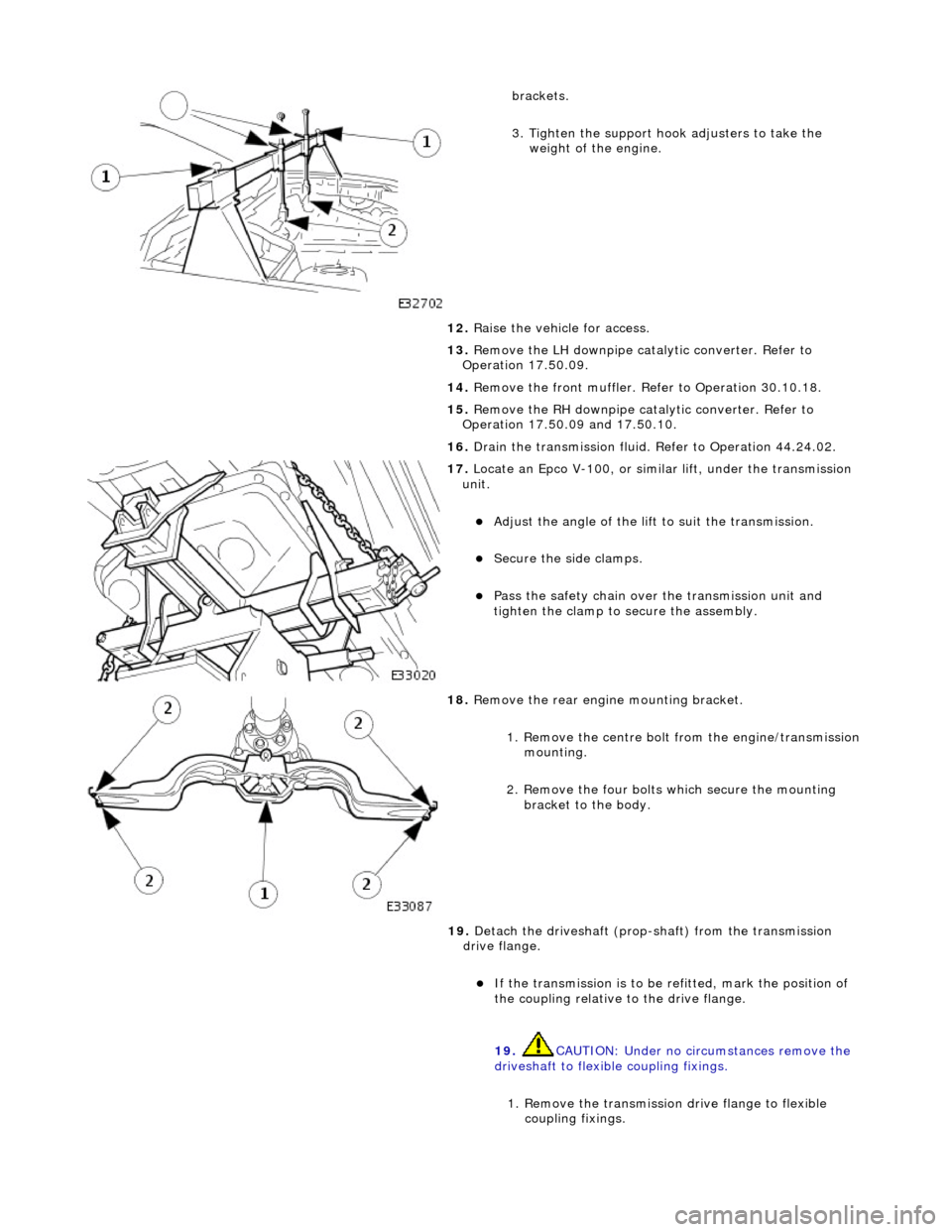
3. Tighten the support hook adjusters to take the weight of the engine.
12. Raise the vehicle for access.
13. Remove the LH downpipe catalytic converter. Refer to
Operation 17.50.09.
14. Remove the front muffler. Re fer to Operation 30.10.18.
15. Remove the RH downpipe catalytic converter. Refer to
Operation 17.50.09 and 17.50.10.
16. Drain the transmission fluid. Refer to Operation 44.24.02.
17. Locate an Epco V-100, or sim ilar lift, under the transmission
unit.
Adjust the angle of the lift to suit the transmission.
Secure the side clamps.
Pass the safety chain over the transmission unit and
tighten the clamp to secure the assembly.
18. Remove the rear engine mounting bracket.
1. Remove the centre bolt from the engine/transmission
mounting.
2. Remove the four bolts which secure the mounting
bracket to the body.
19. Detach the driveshaft (prop- shaft) from the transmission
drive flange.
If the transmission is to be refitted, mark the position of
the coupling relative to the drive flange.
19. CAUTION: Under no circ umstances remove the
driveshaft to flexible coupling fixings.
1. Remove the transmission drive flange to flexible
coupling fixings.
Page 1451 of 2490
20. Lower the transmission unit.
21. Detach the gear selector cable from the transmission unit.
1. Remove the selector cable ball pin to selector lever nut.
2. Lower the transmissi on lift for access.
3. Remove the selector cable to transmission casing bolts.
22. Release the transmission ha rness multiplug bracket.
1. Remove the two bolts which secure the bracket to the
transmission case, noting that one bolt also retains
the dipstick tube.
23. Disconnect the fluid cooler upper pipe.
Remove the bolt which secures the pipe to the cylinder
block and remove the bracket.
Remove the 'banjo' bolt.
Page 1453 of 2490
29. NOTE: Viewed from the rear of the vehicle.
Remove the two bolts which se cure the starter motor power
cable clip.
30. NOTE: Viewed from the rear of the vehicle.
Remove the ground lead bolt.
31. On the LH side.
32. NOTE: Viewed from the rear of the vehicle.
Remove the bolt which secures the cooler upper pipe clip to the
transmission case.
33. NOTE: Viewed from the rear of the vehicle.
Remove the six remaining bolts from the transmission case to
cylinder block.
Page 1454 of 2490
34. NOTE: Do not allow the converter to detach from the
transmission.
Remove the transmission / converter assembly from the
vehicle.
Lower the lift and remove the transmission, ensuring that
the torque converter spigot disengages cleanly.
35. Remove the side clamps and chain for access.
36. Remove the front muffler mounting bracket.
Remove the two bolts which secure the bracket to the
transmission case.
37. Remove the transmission dipstick tube.
1. Remove the fixing which secures the tube to the case.
Discard the filler tube 'O' ring. 2. Fit a blanking plug to the transmission casing orifice.
Page 1458 of 2490
Automatic Transmission/Transaxle - 4.0L SC V8 - AJ26 - Transmission
Installation
Installation
Special Tool(s)
Engine support
303-021
Engine lifting brackets
303-536
1. CAUTION: A new transmission requires a NEW torque
converter.
Installation is the re verse of the removal procedure, noting the
following:
2. Clean all mating faces and relevant parts.
3. Apply lubricant, MOLYCOTE or equivalent to the torque
converter spigot.
4. Fit the screw (lower) securing th e harness link lead heatshield.
Tighten to the specified torque figure.
5. Fit the dipstick lower tube.
Remove the blanking plug and fit a new O-ring seal.
Tighten the bolt to the specified torque figure.
Page 1459 of 2490
6. Fit the mounting bracket for th e front muffler. Tighten the two
bolts to the specified torque figure.
7. Secure the transmission to the engine.
Loosely assemble - Cooler pipe clip bolt.
Loosely assemble - Ground lead bolt.
Loosely assemble - Starter cable clips, two bolts.
Loosely assemble - Catalyst bracket bolts, two each side.
Loosely assemble - Rema ining eight bolts.
Refer to the illustration - tighten in sequence 1,2,3,4 then
in any order.
8. Secure the torque converter to the engine.
1. Fit, but do not tighten, the three bolts which secure the torque converter to the drive plate.
Prevent crankshaft rotation and tighten ALL converter
bolts to the specified torque figure.
2. Fit the blanking plug to the cylinder block access aperture.
9. Secure the oil cooler pipes.
Fit new Dowty washers to each union. Connect the upper
and lower cooler pipes.
Tighten to the specified torque figure.
Page 1464 of 2490
Automatic Transmission/Transaxle External Controls - 4.0L NA V8 -
AJ27/3.2L NA V8 - AJ26 - External Controls
Description and Operation
Introduction
Driver gearshift control is effected by:
The gear shift lever. The accelerator pedal position. The kickdown switch (where fitted). The performance mode pushbutton.
Driver's Selector Module ('J' Gate)
The gear selector lever:
Has seven positions: Park, Reverse, Neutral, Drive, Fourth, Third and Second. Operates the transmission selector shaft and rotary switch, in all positions (except Drive-to-fourth) by means of a
Bowden cable.
Passes driver gearshift requests to the transm ission control module via the rotary switch.
ItemPart NumberDescription
1—Gear selector lever
2—Drive-to-fourth switch connector
3—Neutral position switch connector
4—Park position switch connector
5—Gear selector illumination module
6—Gear selector interlock solenoid
7—Security system Active LED
Page 1465 of 2490

The Drive-to-fourth switch:
Detects when the gear selector lever is moved from Drive to Fourth. Is hard-wired to the transmission control module.
The Neutral position switch:
Is hard-wired to the body processor module. Detects when the gear selector lever is moved to the Neutral position.
The Park position switch:
Is hard-wired to the body processor module. Detects when the gear selector leve r is moved to the Park position.
The gear selector module:
Provides illumination of the gear sele ctor surround, which is dimmable via a CA N signal from the instrument cluster. Provides red illumination, on the gear selector surround, of the gear selected, by CAN signals from the instrument
cluster.
Illuminates the security system Active LED on the gear se lector surround, in response to an input from the body
processor module.
Is connected to the fascia harness via a 12-way connector. Refer to Connec tor Pins Identification, 307-01A.
The gear selector interlock solenoid:
Prevents the gear selector lever from be ing moved from the Park position, unless th e ignition switch is in position II,
and the brake pedal is depressed.
Is controlled by an input from the body processor module.
The seven gear selector positions are:
P : The transmission is mechanically locked (starting available). R : Reverse gear. N : No power to the rear wh eels (starting available). D : All 5 forward gears available. 4 : Upshift to 4th gear only. 3 : Upshift to 3rd gear only. 2 : Upshift to 2nd gear only.
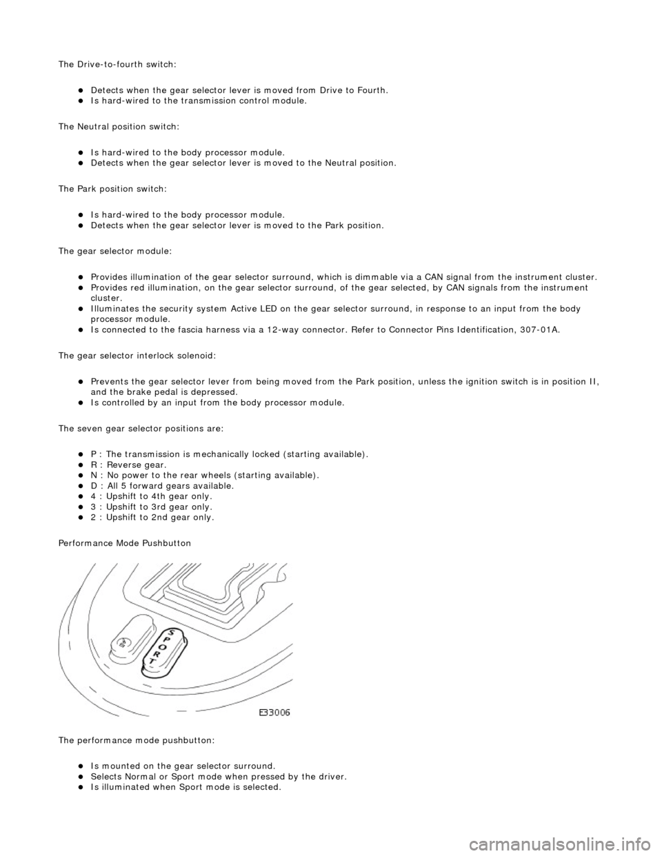
Performance Mode Pushbutton
The performance mode pushbutton:
Is mounted on the gear selector surround. Selects Normal or Sport mode when pressed by the driver. Is illuminated when Sport mode is selected.