Page 1133 of 2490
Intake Air Distribution and Filtering - Su
percharger Outl
et Pipe Gasket
Re
moval and Installation
Remov
al
Installation
1.
R
emove supercharger outlet
duct; refer to 18.50.16.
1. Installation is a reversal of the removal procedure.
Page 1134 of 2490

Intake Air Distribution and Filtering - Thrott
le Body Elbow
Re
mo
val and Installation
Remov
a
l
1.
WARNING: B E
FORE PROCEEDING, IT IS ESSENTIAL THAT
WARNING NOTES GIVEN IN SECTION 100-00 (UNDER HEADING
'SAFETY PRECAUTIONS') AR E READ AND UNDERSTOOD.
Disconnect battery ground cable (IMPORTANT, see SRO
86.15.19 for further information).
2. Re
move air cleaner cover / inta
ke assembly; refer 19.10.30.
3. Remove throttle assemb ly; refer to 19.70.04.
4. Remove exhaust gas recirculation (EGR) valve where installed;
refer 17.45.01.
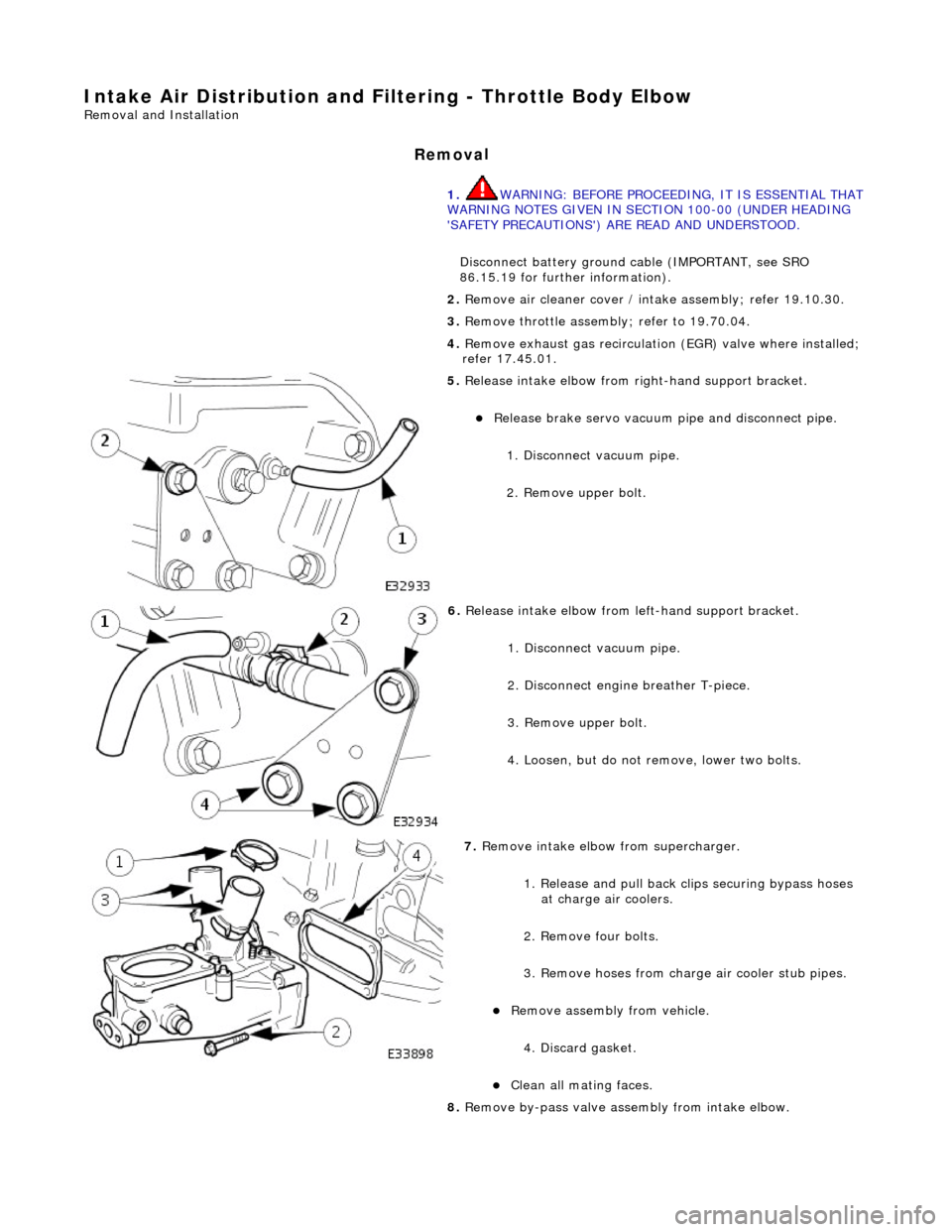
5. Re
lease intake elbow from right-hand support bracket.
Re
lea
se brake servo vacuum pi
pe and disconnect pipe.
1. Disconnect vacuum pipe.
2. Remove upper bolt.
6. Relea
se intake elbow from le
ft-hand support bracket.
1. Disconnect vacuum pipe.
2. Disconnect engine breather T-piece.
3. Remove upper bolt.
4. Loosen, but do not remove, lower two bolts.
7. Re
move intake elbow from supercharger.
1. Release and pull back cl ips securing bypass hoses
at charge air coolers.
2. Remove four bolts.
3. Remove hoses from charge air cooler stub pipes.
Re move as
sembly from vehicle.
4. Discard gasket.
Cle a
n all mating faces.
8. Remove by-pass valve assembly from intake elbow.
Page 1137 of 2490
Intake Air Distribution and Filtering - Throt
tle Body Elbow4.0L NA V8 -
AJ27/3.2L NA V8 - AJ26
Re
moval and Installation
Remov
al
S
pecial Tool(s)
Re
lease tool - quick fit
310-044 (JD 182)
R
elease tool 5 /16 - quick fit
310-054 (JD 203)
1. WARNING: BEFORE PROCEEDING, IT IS ESSENTIAL THAT
THE WARNING NOTES GIVEN IN SECTION 100-00 (UNDER THE
HEADING 'SAFETY PRECAUTIONS') ARE READ AND
UNDERSTOOD.
Disconnect battery ground cable (IMPORTANT, see SRO
86.15.19 for further information).
2. D
epressurize fuel sy
stem; refer to 19.50.02
3. Remove air cleaner cover / intake assembly; refer to 19.10.30.
4. Remove throttle body; refer to 19.70.04.
5. R
elease intake elbow from right-hand support bracket.
Re
lease brake servo vacuum pi
pe and disconnect pipe.
1. Disconnect vacuum pipe.
2. Remove bolt.
6. Release intake elbow from le ft-hand support bracket.
1. Disconnect vacuum pipe.
2. Disconnect engine breather T-piece.
3. Remove bolt.
4. Loosen, but do not remove two bolts.
Page 1142 of 2490

Intake Air Distribution and Filtering - Throttle B
ody Elbow4.0L SC V8 -
AJ26
Re mo
val and Installation
Remova
l
1.
WARNING: BE
FORE PROCEEDING, IT IS ESSENTIAL THAT
WARNING NOTES GIVEN IN SECTION 100-00 (UNDER HEADING
'SAFETY PRECAUTIONS') AR E READ AND UNDERSTOOD.
Disconnect battery ground cable (IMPORTANT, see SRO
86.15.19 for further information).
2. Re
move air cleaner cover / inta
ke assembly; refer 19.10.30.
3. Remove throttle assemb ly; refer to 19.70.04.
4. Remove exhaust gas recirculation (EGR) valve where installed;
refer 17.45.01.
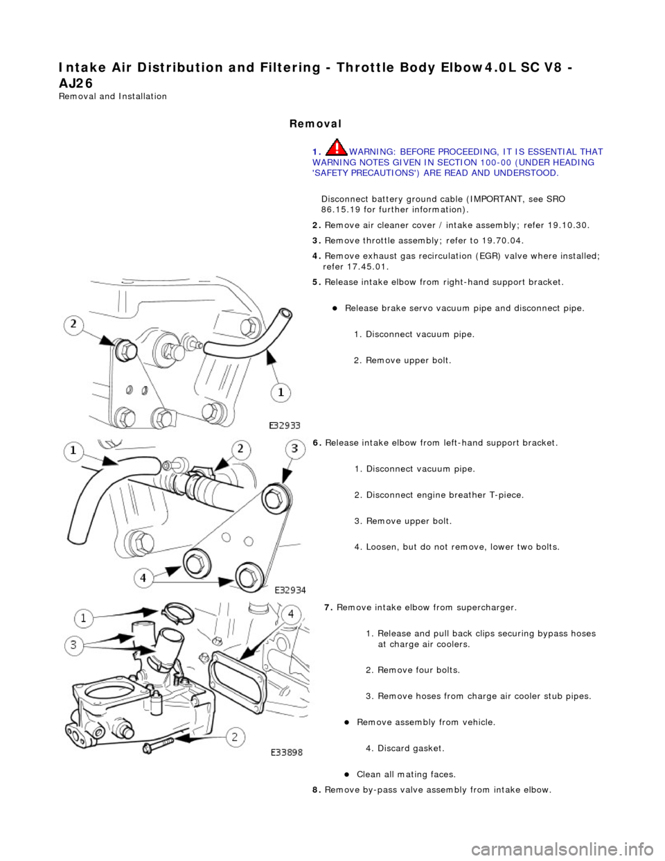
5. Re
lease intake elbow from right-hand support bracket.
Re
lea
se brake servo vacuum pi
pe and disconnect pipe.
1. Disconnect vacuum pipe.
2. Remove upper bolt.
6. Relea
se intake elbow from le
ft-hand support bracket.
1. Disconnect vacuum pipe.
2. Disconnect engine breather T-piece.
3. Remove upper bolt.
4. Loosen, but do not remove, lower two bolts.
7. Re
move intake elbow from supercharger.
1. Release and pull back cl ips securing bypass hoses
at charge air coolers.
2. Remove four bolts.
3. Remove hoses from charge air cooler stub pipes.
Re move as
sembly from vehicle.
4. Discard gasket.
Cle a
n all mating faces.
8. Remove by-pass valve assembly from intake elbow.
Page 1145 of 2490
Intake Air Distribution and Filtering - Throt
tle Body Elbow Gasket
Re
moval and Installation
Remov
al
Installation
1.
R
emove throttle intake elbo
w; refer to (SC)19.70.28.
1. Installation is a reversal of the removal procedure.
Page 1146 of 2490
Intake Air Distribution and Filtering - Throttle B
ody Elbow Gasket4.0L NA
V8 - AJ27/3.2L NA V8 - AJ26
Re mo
val and Installation
Remova
l
Installation
1.
Re
move throttle intake el
bow; refer to 19.70.28.
1. Installation is a reversal of the removal procedure.
Page 1147 of 2490
Intake Air Distribution and Filtering - Throt
tle Body Elbow Gasket4.0L SC
V8 - AJ26
Re
moval and Installation
Remov
al
Installation
1.
R
emove throttle intake elbo
w; refer to (SC)19.70.28.
1. Installation is a reversal of the removal procedure.
Page 1152 of 2490

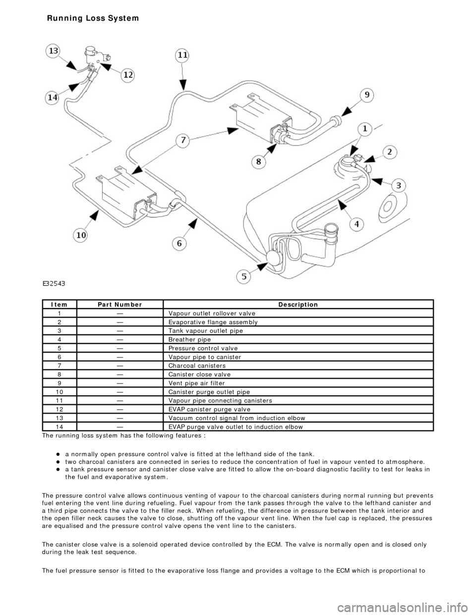
The ru nning loss
system has the following features :
a
normall
y open pressure control valve is fi
tted at the lefthand side of the tank.
two charcoal
canisters are connected in series to reduce th
e concentration of fuel in vapour vented to atmosphere.
a t
ank pressure sensor and canister close
valve are fitted to allow the on-board di agnostic facility to test for leaks in
the fuel and evaporative system.
The pressure control valve allows continuo us venting of vapour to the charcoal canisters during normal running but prevents
fuel entering the vent line duri ng refueling. Fuel vapour from the tank passes through the valve to the lefthand canister and
a third pipe connects the valve to the fill er neck. When refueling, the difference in pressure betw een the tank interior and
the open filler neck causes the valve to cl ose, shutting off the vapour vent line. Wh en the fuel cap is replaced, the pressures
are equalised and the pressure control valve opens the vent line to the canisters.
The canister close valve is a solenoid operated device controlled by the ECM. The valve is normally open and is closed only
during the leak test sequence.
The fuel pressure sensor is fitted to th e evaporative loss flange and provides a volt age to the ECM which is proportional to
Ite
m
Par
t
Number
De
scr
iption
1—Vapour outl
et rol
lover valve
2—Evaporative flan
ge assembly
3—Tank vapour outlet pipe
4—Breather pipe
5—Pressure control
valve
6—Vapour pipe to canister
7—Charcoal cani
sters
8—Cani
st
er close valve
9—Vent pi
pe ai
r filter
10—Canister purge ou
tlet pipe
11—Vapour pipe conn
ecting canisters
12—EVAP canister purge v
a
lve
13—Vacuu
m
control signal from induction elbow
14—EVAP pu
rge valve outlet to induction elbow
Running Loss Sys
tem