Page 389 of 2490
Install brake pads.
1
. Install pads.
2. Position anti-rattle spring.
3. Install pins - make sure pin collets are fully engaged
into caliper.
4. Repeat above procedure to install opposite side brake pads.
5. Fit wheels.
For additional information, refer to: Wheel and Tire
(20
4-04
Wheels and Tires, Remo val and Installation).
6. Remove stands an d lower vehicle.
For additional information, refer to: Using the Workshop Jack
(10
0-02 Jacking and Lifting, General Procedures).
7. CAUTI
ON: Remove brake flui
d spillage immediately from
paint work, with clean water.
Check brake fluid level.
Check brak
e fluid level is
at the maximum mark.
Re
move cloth.
Fi
t cap.
8.
R
emove paint work protection
covers, and close engine
compartment.
9. Start the engine and repeatedly press the brake pedal until
brake pressure is evident.
Page 407 of 2490

The t
andem master cylinder contains two in
dependent pistons, fluid pressure to each brake circuit is controlled by its own
individual piston. Brake fluid is supplied to the master cylinder by the reservoir, which is divided into two sections to preve nt
total fluid loss should one of the circuits fail. A port situated at the bottom of each section of the reservoir supplies the f luid
to each piston.
The fluid reservoir has a fluid-le vel indicator switch installed, which operates when the fluid level is low, causing the brake
fluid level warning-lamp to illuminate.
Bra
ke Caliper
The brake
calipers are of the single piston
type. The caliper carrier, which is secured to the vertical link by two bolts, carr ies
the single-piston caliper housing. The cali per housing is secured to the caliper carrier by two guide-pins and an anti-rattle
spring. When the brakes are applied, the caliper-housing piston pushes the brake pad in front of it, to wards the brake disc.
This movement forces the calipe r housing to move along the guid e-pins, in the opposite direction of the piston, to apply the
second brake pad.
Br
embo Brake Caliper
The four
cylinder brake caliper is rigidly attached to the vert
ical link via an anchor bracket. The caliper is a split assembly
with each side of the caliper, housing two pistons. The two-pairs of opposed pistons act direct ly on the brake pads mounted
one each side of the disc.
Mast
er Cylinder and Reservoir
Page 2065 of 2490

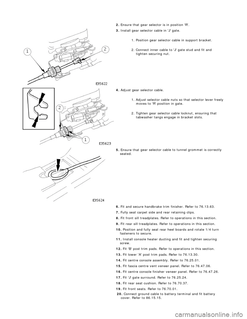
2. Ensure that
gear selector is in position 'R'.
3. Inst
all gear selector cable in 'J' gate.
1. Position gear selector cable in support bracket.
2. Connect inner cable to 'J' gate stud and fit and
tighten securing nut.
4. Adjust
gear selector cable.
1. Adjust selector cable nuts so that selector lever freely
moves to 'R' position in gate.
2. Tighten gear selector ca ble locknut, ensuring that
tabwasher tangs engage in bracket slots.
5. Ensure that
gear selector cable
to tunnel grommet is correctly
seated.
6. Fit and secure handbrake trim finisher. Refer to 76.13.63.
7. Fully seat carpet side and rear retaining clips.
8. Fit front sill treadplates. Refer to operations in this section.
9. Fit rear sill treadplates. Refer to operations in this section.
10. Position and fully seat rear heel boards and rotate 1/4 turn
fasteners to secure.
11. Install console heater ducting and fit and tighten securing
screw.
12. Fit 'B' post trim pads. Refer to operations in this section.
13. Fit lower 'A' post trim pads. Refer to 76.13.30.
14. Fit centre console asse mbly. Refer to 76.25.01.
15. Fit fascia centre ve nt veneer panel. Refer to 76.47.06.
16. Fit centre console finisher vene er panel. Refer to 76.47.26.
17. Fit 'J' gate surround. Refer to 76.25.24.
18. Fit rear seat cushion. Refer to 76.70.37.
19. Fit front seats. Refer to 76.70.01.
20
.
Connect ground cable to batt ery terminal and fit battery
cover. Refer to 86.15.15.