1998 JAGUAR X308 engine
[x] Cancel search: enginePage 1210 of 2490
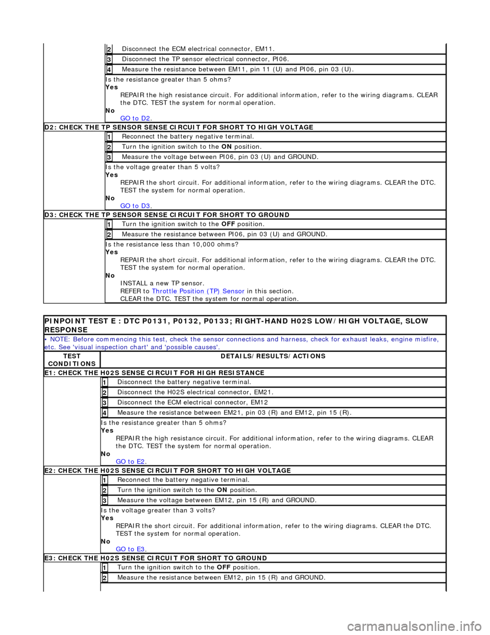
Di
sconnect the ECM electrical connector, EM11.
2
Disc
onne
ct the TP sensor electrical connector, PI06.
3
Meas
ure t
he resistance between EM11, pin 11 (U) and PI06, pin 03 (U).
4
Is th
e res
istance greater than 5 ohms?
Yes REPAIR the high resistance circui t. For additional information, refer to the wiring diagrams. CLEAR
the DTC. TEST the system for normal operation.
No GO to D2
.
D2
: CHECK THE TP SENSOR SENSE CIRCUIT FOR SHORT TO HIGH VOLTAGE
Re
connect the battery negative terminal.
1
Turn the ignition swit
ch to the ON
position.
2
Me
asure the voltage between PI06, pin 03 (U) and GROUND.
3
Is the volt
age greater than 5 volts?
Yes REPAIR the short circuit. For addi tional information, refer to the wiring diagrams. CLEAR the DTC.
TEST the system for normal operation.
No GO to D3
.
D3: CH
ECK THE TP SENSOR SENSE CIRCUIT FOR SHORT TO GROUND
Turn the ignition swi
t
ch to the OFF
position.
1
Measure t
he resistance between PI06, pin 03 (U) and GROUND.
2
Is
t
he resistance less than 10,000 ohms?
Yes REPAIR the short circuit. For addi tional information, refer to the wiring diagrams. CLEAR the DTC.
TEST the system for normal operation.
No INSTALL a new TP sensor.
REFER to Throttle Position (TP) Sensor
in this
section.
CLEAR the DTC. TEST the syst em for normal operation.
PI
NPOINT TEST E : DTC P0131, P0132, P0133; RIGHT-HAND H02S LOW/HIGH VOLTAGE, SLOW
RESPONSE
•
NOTE: Before commencing this test, check the sensor connect
ions and harness, check for exhaust leaks, engine misfire,
etc. See 'visual inspection ch art' and 'possible causes'.
TES
T
CONDITIONS
D E
TAILS/RESULTS/ACTIONS
E1
: CHECK THE H02S
SENSE CI
RCUIT FOR HIGH RESISTANCE
Disc
onnect the battery negative terminal.
1
D
is
connect the H02S electrical connector, EM21.
2
Disc
onne
ct the ECM electrical connector, EM12
3
Meas
ure t
he resistance between EM21, pin 03 (R) and EM12, pin 15 (R).
4
Is th
e res
istance greater than 5 ohms?
Yes REPAIR the high resistance circui t. For additional information, refer to the wiring diagrams. CLEAR
the DTC. TEST the system for normal operation.
No GO to E2
.
E2: CHECK THE H02S
SENSE CIRCUI
T FOR SHORT TO HIGH VOLTAGE
Re
connect the battery negative terminal.
1
Turn the ignition swi
t
ch to the ON
position.
2
Measure t
he voltage between EM12, pin 15 (R) and GROUND.
3
Is th
e volt
age greater than 3 volts?
Yes REPAIR the short circuit. For addi tional information, refer to the wiring diagrams. CLEAR the DTC.
TEST the system for normal operation.
No GO to E3
.
E3: CHECK THE H02S
SENSE CI
RCUIT FOR SHORT TO GROUND
Turn the ignition swi t
ch to the OFF
position.
1
Measure t
he resistance between EM12, pin 15 (R) and GROUND.
2
Page 1212 of 2490
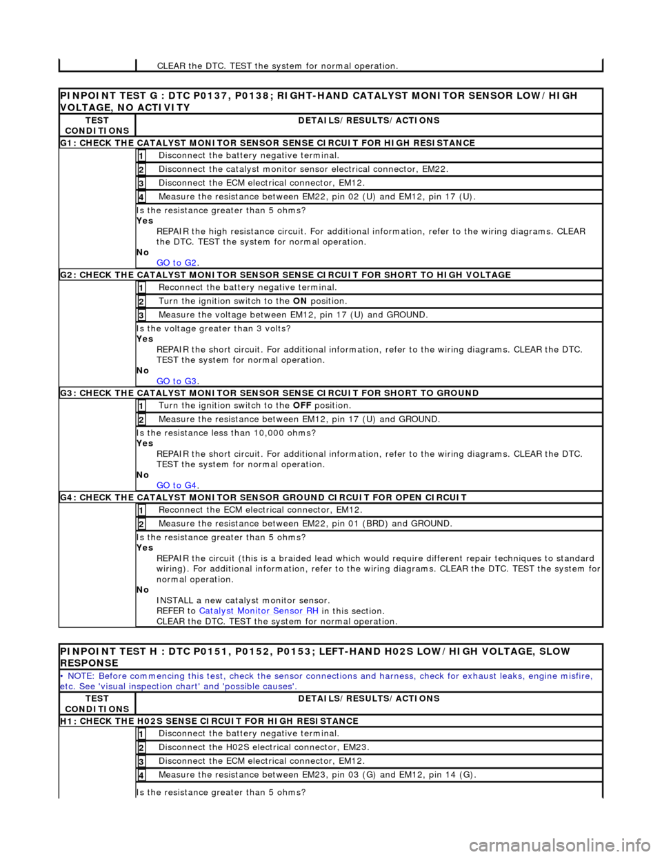
CLEAR th
e DTC. TEST the syst
em for normal operation.
PINPOINT TES
T G : DTC P0137, P0138; RIGH
T-HAND CATALYST MONITOR SENSOR LOW/HIGH
VOLTAGE, NO ACTIVITY
TE S
T
CONDITIONS
D E
TAILS/RESULTS/ACTIONS
G1
: C
HECK THE CATALYST MONITOR SENSOR SENSE CIRCUIT FOR HIGH RESISTANCE
Di
sc
onnect the battery negative terminal.
1
Di
sc
onnect the catalyst monitor sensor electrical connector, EM22.
2
Disc
onne
ct the ECM electrical connector, EM12.
3
Meas
ure t
he resistance between EM22, pin 02 (U) and EM12, pin 17 (U).
4
Is th
e res
istance greater than 5 ohms?
Yes REPAIR the high resistance circui t. For additional information, refer to the wiring diagrams. CLEAR
the DTC. TEST the system for normal operation.
No GO to G2
.
G2: CHECK
THE CATALYST MONITOR SENSOR SE
NSE CIRCUIT FOR SHORT TO HIGH VOLTAGE
Re
connect the battery negative terminal.
1
Turn the ignition swi
t
ch to the ON
position.
2
Measure t
he voltage between EM12, pin 17 (U) and GROUND.
3
Is th
e volt
age greater than 3 volts?
Yes REPAIR the short circuit. For addi tional information, refer to the wiring diagrams. CLEAR the DTC.
TEST the system for normal operation.
No
GO to G3
.
G3: CHECK
THE CATALYST MONITOR SENSOR
SENSE CIRCUIT FOR SHORT TO GROUND
Turn the ignition swit
ch to the OFF
position.
1
Measure t
he resistance between EM12, pin 17 (U) and GROUND.
2
Is t
he resistance less than 10,000 ohms?
Yes REPAIR the short circuit. For addi tional information, refer to the wiring diagrams. CLEAR the DTC.
TEST the system for normal operation.
No GO to G4
.
G4: CHECK
THE CATALYST MONITOR SENSOR
GROUND CIRCUIT FOR OPEN CIRCUIT
Reconn
ect the ECM electrical connector, EM12.
1
Meas
ure t
he resistance between EM22, pin 01 (BRD) and GROUND.
2
Is th
e res
istance greater than 5 ohms?
Yes REPAIR the circuit (this is a braide d lead which would require different repair techniques to standard
wiring). For additional information, refer to the wiring diagrams. CL EAR the DTC. TEST the system for
normal operation.
No INSTALL a new catalyst monitor sensor.
REFER to Catalyst Monitor Sensor RH
in this
section.
CLEAR the DTC. TEST the syst em for normal operation.
PINPOINT TES
T H : DTC P0151, P0152, P0153;
LEFT-HAND H02S LOW/HIGH VOLTAGE, SLOW
RESPONSE
•
NOTE: Before commencing this test, check the sensor connect
ions and harness, check for exhaust leaks, engine misfire,
etc. See 'visual inspection ch art' and 'possible causes'.
TES
T
CONDITIONS
D E
TAILS/RESULTS/ACTIONS
H1:
C
HECK THE H02S SENSE CIRCUIT FOR HIGH RESISTANCE
Di
sc
onnect the battery negative terminal.
1
D
is
connect the H02S electrical connector, EM23.
2
Disc
onne
ct the ECM electrical connector, EM12.
3
Meas
ure t
he resistance between EM23, pin 03 (G) and EM12, pin 14 (G).
4
Is th
e res
istance greater than 5 ohms?
Page 1220 of 2490
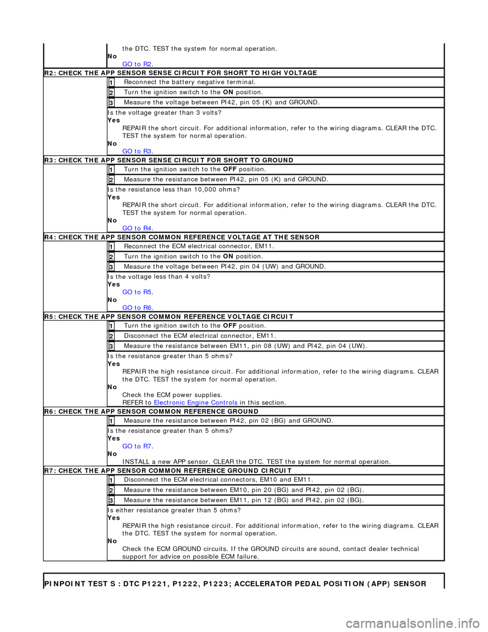
the DT
C. TEST the system for normal operation.
No GO to R2
.
R2: CHECK TH
E APP SENSOR SENSE CIRCUIT FOR SHORT TO HIGH VOLTAGE
R
e
connect the battery negative terminal.
1
Turn the ignition swi
t
ch to the ON
position.
2
Me
asure the voltage between PI42, pin 05 (K) and GROUND.
3
Is th
e volt
age greater than 3 volts?
Yes REPAIR the short circuit. For addi tional information, refer to the wiring diagrams. CLEAR the DTC.
TEST the system for normal operation.
No GO to R3
.
R3: CHECK THE APP SENSOR SENS
E CIRCUIT FOR SHORT TO GROUND
Turn the ignition swi
t
ch to the OFF
position.
1
Me
asure the resistance between PI42, pin 05 (K) and GROUND.
2
Is
t
he resistance less than 10,000 ohms?
Yes REPAIR the short circuit. For addi tional information, refer to the wiring diagrams. CLEAR the DTC.
TEST the system for normal operation.
No GO to R4
.
R4: CHECK THE APP SENSOR COM
MON
REFERENCE VOLTAGE AT THE SENSOR
Reconn
ect the ECM electrical connector, EM11.
1
Turn the ignition swi
t
ch to the ON
position.
2
Measure t
he voltage between PI42, pin 04 (UW) and GROUND.
3
Is th
e volt
age less than 4 volts?
Yes GO to R5
.
No
GO to R6
.
R5: CHECK THE APP SENSOR COM
M
ON REFERENCE VOLTAGE CIRCUIT
Turn the ignition swit
ch to the OFF
position.
1
Di
sconnect the ECM electrical connector, EM11.
2
Measure t
he resistance between EM11,
pin 08 (UW) and PI42, pin 04 (UW).
3
Is the res
istance greater than 5 ohms?
Yes REPAIR the high resistance circui t. For additional information, refer to the wiring diagrams. CLEAR
the DTC. TEST the system for normal operation.
No Check the ECM power supplies.
REFER to Electronic Engine Controls
in this
section.
R6: CHECK THE APP
SENSOR COM
MON REFERENCE GROUND
Meas
ure t
he resistance between PI42, pin 02 (BG) and GROUND.
1
Is th
e res
istance greater than 5 ohms?
Yes GO to R7
.
No
INST
ALL a new APP sensor. CLEAR the DTC.
TEST the system for normal operation.
R7: CHECK THE APP SENSOR COM
MON REFERENCE GROUND CIRCUIT
D
i
sconnect the ECM electrical connectors, EM10 and EM11.
1
Measure t
he resistance between EM10,
pin 20 (BG) and PI42, pin 02 (BG).
2
Measure t
he resistance between EM11,
pin 12 (BG) and PI42, pin 02 (BG).
3
Is either resistance greater
than 5 ohms?
Yes REPAIR the high resistance circui t. For additional information, refer to the wiring diagrams. CLEAR
the DTC. TEST the system for normal operation.
No Check the ECM GROUND circuits. If the GROUND circuits are sound, contact dealer technical
support for advice on possible ECM failure.
PINPO
INT TEST S : DTC P1221, P1222, P1223;
ACCELERATOR PEDAL POSITION (APP) SENSOR
Page 1221 of 2490
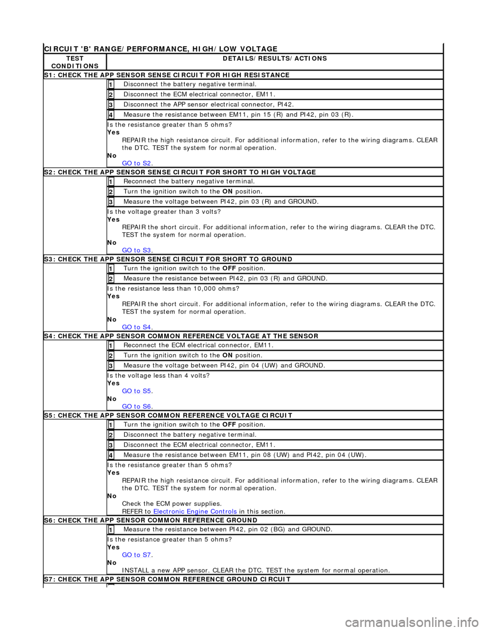
CIRCUI
T 'B' RANGE/PERFORMANCE, HIGH/LOW VOLTAGE
TE
ST
CONDITIONS
D
ETAILS/RESULTS/ACTIONS
S1: CHECK
THE APP SENSOR SENSE CIRCUIT FOR HIGH RESISTANCE
Di
sconnect the battery negative terminal.
1
D
isconnect the ECM electrical connector, EM11.
2
Di
sconnect the APP sensor electrical connector, PI42.
3
Meas
ure the resistance between EM11, pin 15 (R) and PI42, pin 03 (R).
4
Is th
e resistance greater than 5 ohms?
Yes REPAIR the high resistance circui t. For additional information, refer to the wiring diagrams. CLEAR
the DTC. TEST the system for normal operation.
No GO to S2
.
S
2: CHECK THE APP SENSOR SENSE CIRCUIT FOR SHORT TO HIGH VOLTAGE
R
econnect the battery negative terminal.
1
Turn the ignition swi
tch to the ON
position.
2
M
easure the voltage between PI42, pin 03 (R) and GROUND.
3
Is th
e voltage greater than 3 volts?
Yes REPAIR the short circuit. For addi tional information, refer to the wiring diagrams. CLEAR the DTC.
TEST the system for normal operation.
No GO to S3
.
S
3: CHECK THE APP SENSOR SENSE CIRCUIT FOR SHORT TO GROUND
Turn the ignition swi
tch to the OFF
position.
1
Meas
ure the resistance between PI42, pin 03 (R) and GROUND.
2
Is
the resistance less than 10,000 ohms?
Yes REPAIR the short circuit. For addi tional information, refer to the wiring diagrams. CLEAR the DTC.
TEST the system for normal operation.
No GO to S4
.
S4:
CHECK THE APP SENSOR COMMON REFERENCE VOLTAGE AT THE SENSOR
Re
connect the ECM electrical connector, EM11.
1
Turn the ignition swi
tch to the ON
position.
2
Meas
ure the voltage between PI42, pin 04 (UW) and GROUND.
3
Is th
e voltage less than 4 volts?
Yes GO to S5
.
No
GO to S6
.
S5: CHECK
THE APP SENSOR COMM
ON REFERENCE VOLTAGE CIRCUIT
Turn the ignition swi
tch to the OFF
position.
1
Di
sconnect the battery negative terminal.
2
D
isconnect the ECM electrical connector, EM11.
3
Meas
ure the resistance between EM11,
pin 08 (UW) and PI42, pin 04 (UW).
4
Is th
e resistance greater than 5 ohms?
Yes REPAIR the high resistance circui t. For additional information, refer to the wiring diagrams. CLEAR
the DTC. TEST the system for normal operation.
No Check the ECM power supplies.
REFER to Electronic Engine Controls
in this section.
S6: CHECK
THE APP SENSOR COMMON REFERENCE GROUND
Meas
ure the resistance between PI42, pin 02 (BG) and GROUND.
1
Is th
e resistance greater than 5 ohms?
Yes GO to S7
.
No
INSTALL a new APP sensor. CLEAR the DTC. TEST the system for normal operation.
S7: CHECK
THE APP SENSOR COMM
ON REFERENCE GROUND CIRCUIT
Page 1228 of 2490
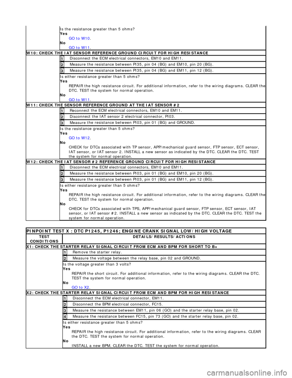
Is the res
istance greater than 5 ohms?
Yes GO to W10
.
No
GO to W11
.
W10 :
CHECK THE IAT SENSOR REFERENCE
GROUND CIRCUIT FOR HIGH RESISTANCE
Di
sconnect the ECM electrical connectors, EM10 and EM11.
1
Meas
ure t
he resistance between PI35,
pin 04 (BG) and EM10, pin 20 (BG).
2
Measure t
he resistance between PI35,
pin 04 (BG) and EM11, pin 12 (BG).
3
Is either resistance greater
than 5 ohms?
Yes REPAIR the high resistance circuit. For additional information, refer to the wiring diagrams. CLEAR the
DTC. TEST the system for normal operation.
No GO to W11
.
W11 :
CHECK THE SENSOR REFERENCE GROUND AT THE IAT SENSOR #2
Re
conn
ect the ECM electrical connectors, EM10 and EM11.
1
Di
sc
onnect the IAT sensor 2 electrical connector, PI03.
2
Meas
ure t
he resistance between PI03, pin 01 (BG) and GROUND.
3
Is th
e res
istance greater than 5 ohms?
Yes GO to W12
.
No
CHECK
for DTCs associated with TP sensor, APP/
mechanical guard sensor, FTP sensor, ECT sensor,
IAT sensor, or IAT sensor 2. INST ALL a new sensor as indicated by the DTC. CLEAR the DTC. TEST
the system for normal operation.
W12 :
CHECK THE IAT SENSOR #2 REFERENC
E GROUND CIRCUIT FOR HIGH RESISTANCE
Di
sconnect the ECM electrical connectors, EM10 and EM11.
1
Meas
ure t
he resistance between PI03,
pin 01 (BG) and EM10, pin 20 (BG).
2
Measure t
he resistance between PI03,
pin 01 (BG) and EM11, pin 12 (BG).
3
Is either resistance greater
than 5 ohms?
Yes REPAIR the high resistance circuit. For additional information, refer to the wiring diagrams. CLEAR the
DTC. TEST the system for normal operation.
No CHECK for DTCs associated with TPS, APP/mechanical guard sensor, FTP sensor, ECT sensor, IAT
sensor, or IAT sensor #2. INSTALL a new sensor as indicated by the DTC. CLEAR the DTC. TEST the
system for normal operation.
PINPO
INT TEST X : DTC P1245, P1246; ENGINE CRANK SIGNAL LOW/HIGH VOLTAGE
TE
S
T
CONDITIONS
D E
TAILS/RESULTS/ACTIONS
X
1
: CHECK THE STARTER RELAY SIGNAL CIRC
UIT FROM ECM AND BPM FOR SHORT TO B+
Re
move the starter relay.
1
Meas
ure t
he voltage between the
relay base, pin 02 and GROUND.
2
Is the volt
age greater than 3 volts?
Yes REPAIR the short circuit. For addi tional information, refer to the wiring diagrams. CLEAR the DTC.
TEST the system for normal operation.
No GO to X2
.
X2
: CHECK THE STARTER RELAY SIGNAL CIRCUI
T FROM ECM AND BPM FOR HIGH RESISTANCE
Di
sconnect the ECM electrical connector, EM11.
1
Disc
onne
ct the BPM electrical connector, FC15.
2
Meas
ure t
he resistance between EM11, pin 06
(GO) and the starter relay base, pin 02.
3
Measure t
he resistance between FC15, pin 73
(GO) and the starter relay base, pin 02.
4
Is either resistance greater
than 5 ohms?
Yes REPAIR the high resistance circui t. For additional information, refer to the wiring diagrams. CLEAR
the DTC. TEST the system for normal operation.
No INSTALL a new BPM. CLEAR the DTC. TEST the system for normal operation.
Page 1230 of 2490
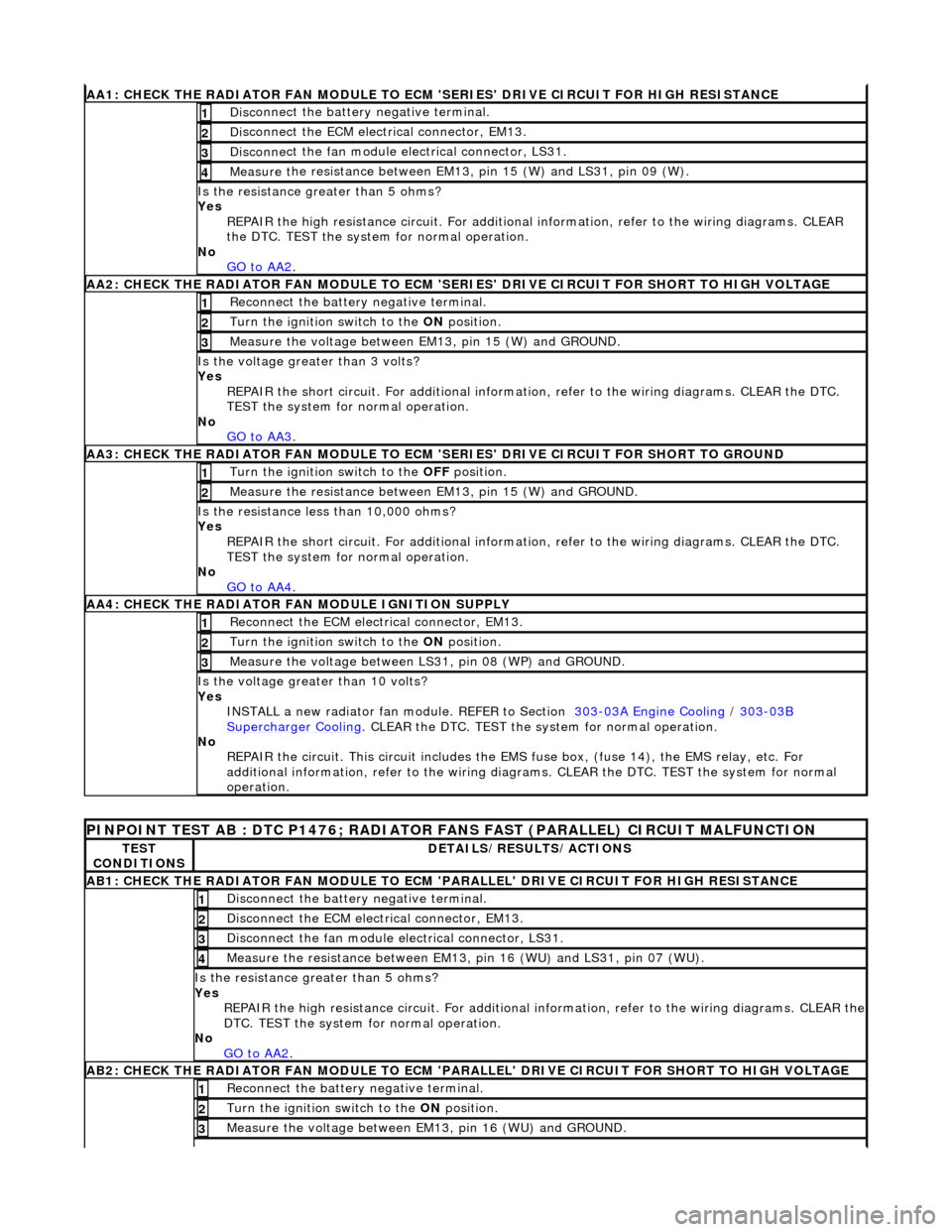
AA1: CHECK THE RA
DIATOR FAN MODULE TO ECM
'SERIES' DRIVE CIRCUIT FOR HIGH RESISTANCE
Disc
onnect the battery negative terminal.
1
D
i
sconnect the ECM electrical connector, EM13.
2
Disc
onne
ct the fan module electrical connector, LS31.
3
Meas
ure t
he resistance between EM13, pin 15 (W) and LS31, pin 09 (W).
4
Is th
e res
istance greater than 5 ohms?
Yes REPAIR the high resistance circui t. For additional information, refer to the wiring diagrams. CLEAR
the DTC. TEST the system for normal operation.
No GO to AA2
.
AA2: CHECK THE RA
DIATOR FAN MODULE TO ECM 'SER
IES' DRIVE CIRCUIT FOR SHORT TO HIGH VOLTAGE
Re
connect the battery negative terminal.
1
Turn the ignition swit
ch to the
ON position.
2
Measure t
he voltage between EM13, pin 15 (W) and GROUND.
3
Is the volt
age greater than 3 volts?
Yes REPAIR the short circuit. For addi tional information, refer to the wiring diagrams. CLEAR the DTC.
TEST the system for normal operation.
No GO to AA3
.
AA3: CHECK THE R A
DIATOR FAN MODULE TO ECM
'SERIES' DRIVE CIRCUIT FOR SHORT TO GROUND
Turn the ignition swit
ch to the
OFF position.
1
Meas ure t
he resistance between EM13, pin 15 (W) and GROUND.
2
Is
t
he resistance less than 10,000 ohms?
Yes
REPAIR the short circuit. For addi tional information, refer to the wiring diagrams. CLEAR the DTC.
TEST the system for normal operation.
No GO to AA4
.
AA4:
CHECK THE RADIATOR FAN MODULE IGNITION SUPPLY
Reconn
ect the ECM electrical connector, EM13.
1
Turn the ignition swit
ch to the
ON position.
2
Measure the voltage between LS 31,
pin 08 (WP) and GROUND.
3
Is the vol
t
age greater than 10 volts?
Yes INSTALL a new radiator fan module. REFER to Section 303
-03
A Engine Cooling
/
303-03B Supercharger Cooli
ng
. CLEA
R the DTC. TEST the sy stem f
or normal operation.
No REPAIR the circuit. This circui t includes the EMS fuse box, (f use 14), the EMS relay, etc. For
additional information, refer to the wiring diagrams. CLEAR the DT C. TEST the system for normal
operation.
PINPOINT TE ST
AB : DTC P1476; RADIATOR
FANS FAST (PARALLEL) CIRCUIT MALFUNCTION
TES
T
CONDITIONS
D E
TAILS/RESULTS/ACTIONS
AB1
:
CHECK THE RADIATOR FAN MODULE TO ECM
'PARALLEL' DRIVE CIRCUIT FOR HIGH RESISTANCE
Disc
onnect the battery negative terminal.
1
D
i
sconnect the ECM electrical connector, EM13.
2
Disc
onne
ct the fan module electrical connector, LS31.
3
Meas
ure t
he resistance between EM13, pin 16 (WU) and LS31, pin 07 (WU).
4
Is th
e res
istance greater than 5 ohms?
Yes REPAIR the high resistance circuit. For additional information, refer to the wiring diagrams. CLEAR the
DTC. TEST the system for normal operation.
No GO to AA2
.
AB2:
CHECK THE RADIATOR FAN MODULE TO ECM 'PARALLEL' DRIVE CIRCUIT FOR SHORT TO HIGH VOLTAGE
R
e
connect the battery negative terminal.
1
Turn the ignition swi
t
ch to the ON
position.
2
Measure t
he voltage between EM13, pin 16 (WU) and GROUND.
3
Page 1231 of 2490
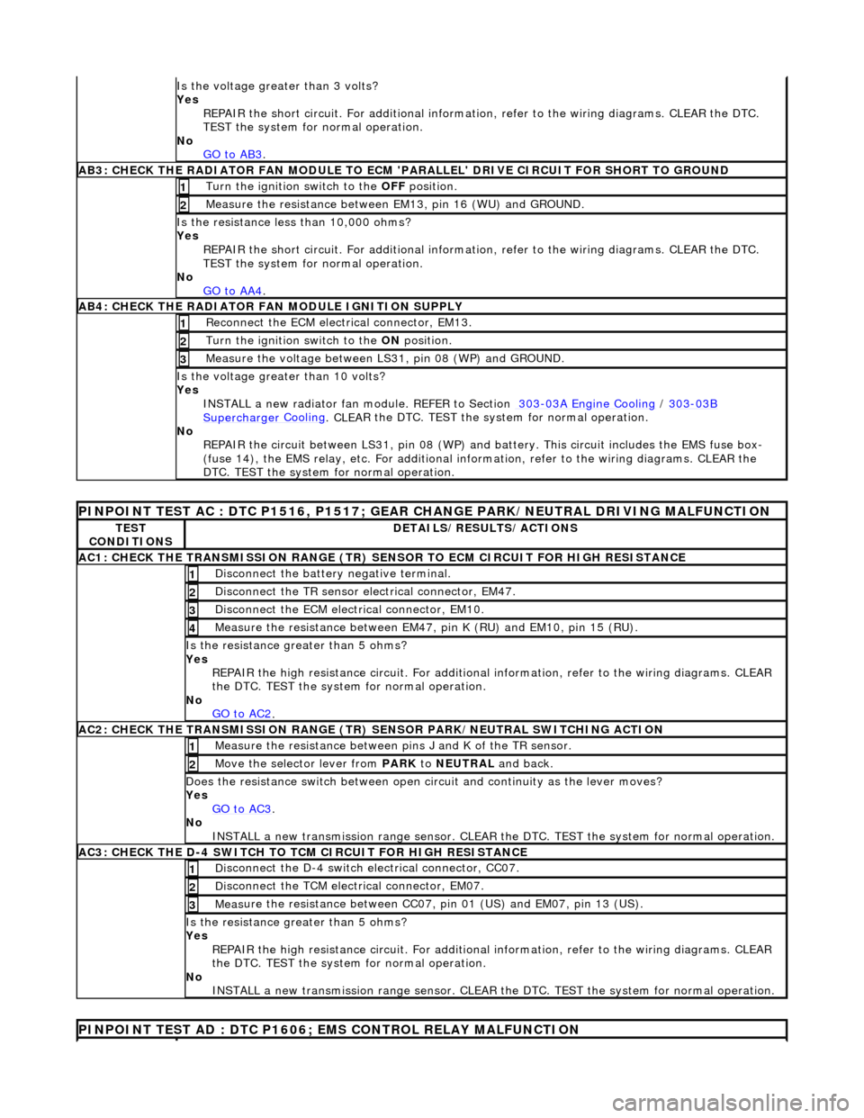
Is th
e voltage greater than 3 volts?
Yes REPAIR the short circuit. For addi tional information, refer to the wiring diagrams. CLEAR the DTC.
TEST the system for normal operation.
No GO to AB3
.
AB3
: CHECK THE RADIATOR FAN MODULE TO ECM
'PARALLEL' DRIVE CIRCUIT FOR SHORT TO GROUND
Turn the ignition swi
tch to the OFF
position.
1
Meas
ure the resistance between EM13, pin 16 (WU) and GROUND.
2
Is
the resistance less than 10,000 ohms?
Yes
REPAIR the short circuit. For addi tional information, refer to the wiring diagrams. CLEAR the DTC.
TEST the system for normal operation.
No GO to AA4
.
AB4
: CHECK THE RADIATOR FAN MODULE IGNITION SUPPLY
Re
connect the ECM electrical connector, EM13.
1
Turn the ignition swi
tch to the ON
position.
2
Measure the
voltage between LS
31, pin 08 (WP) and GROUND.
3
Is the vol
tage greater than 10 volts?
Yes INSTALL a new radiator fan module. REFER to Section 303
-0
3A Engine Cooling
/
30
3
-03
B
Supercharger
Cooling
. CLEA
R the DTC. TEST the sy
stem for normal operation.
No REPAIR the circuit between LS31, pin 08 (WP) and battery. This circuit includes the EMS fuse box-
(fuse 14), the EMS relay, etc. For additional information, refer to the wiring diagrams. CLEAR the
DTC. TEST the system for normal operation.
P
INPOINT TEST AC : DTC P1516, P1517; GEAR
CHANGE PARK/NEUTRAL DRIVING MALFUNCTION
TE
ST
CONDITIONS
D
ETAILS/RESULTS/ACTIONS
AC1: CH
ECK THE TRANSMISSION RANGE (TR) SE
NSOR TO ECM CIRCUIT FOR HIGH RESISTANCE
Di
sconnect the battery negative terminal.
1
Di
sconnect the TR sensor el
ectrical connector, EM47.
2
D
isconnect the ECM electrical connector, EM10.
3
Meas
ure the resistance between EM47, pin K (RU) and EM10, pin 15 (RU).
4
Is th
e resistance greater than 5 ohms?
Yes REPAIR the high resistance circui t. For additional information, refer to the wiring diagrams. CLEAR
the DTC. TEST the system for normal operation.
No GO to AC2
.
AC2: CH
ECK THE TRANSMISSION RANGE (TR)
SENSOR PARK/NEUTRAL SWITCHING ACTION
Meas
ure the resistance between pi
ns J and K of the TR sensor.
1
Mo
ve the selector lever from
PARK to NEUTRAL and back.
2
D
oes the resistance switch between open ci
rcuit and continuity as the lever moves?
Yes GO to AC3
.
No
INSTALL a new transmission range sensor. CLEAR th e DTC. TEST the system for normal operation.
AC3: CH
ECK THE D-4 SWITCH TO
TCM CIRCUIT FOR HIGH RESISTANCE
Di
sconnect the D-4 switch electrical connector, CC07.
1
Di
sconnect the TCM electrical connector, EM07.
2
Meas
ure the resistance between CC07,
pin 01 (US) and EM07, pin 13 (US).
3
Is th
e resistance greater than 5 ohms?
Yes REPAIR the high resistance circui t. For additional information, refer to the wiring diagrams. CLEAR
the DTC. TEST the system for normal operation.
No INSTALL a new transmission range sensor. CLEAR th e DTC. TEST the system for normal operation.
P
INPOINT TEST AD : DTC P1606;
EMS CONTROL RELAY MALFUNCTION
Page 1233 of 2490
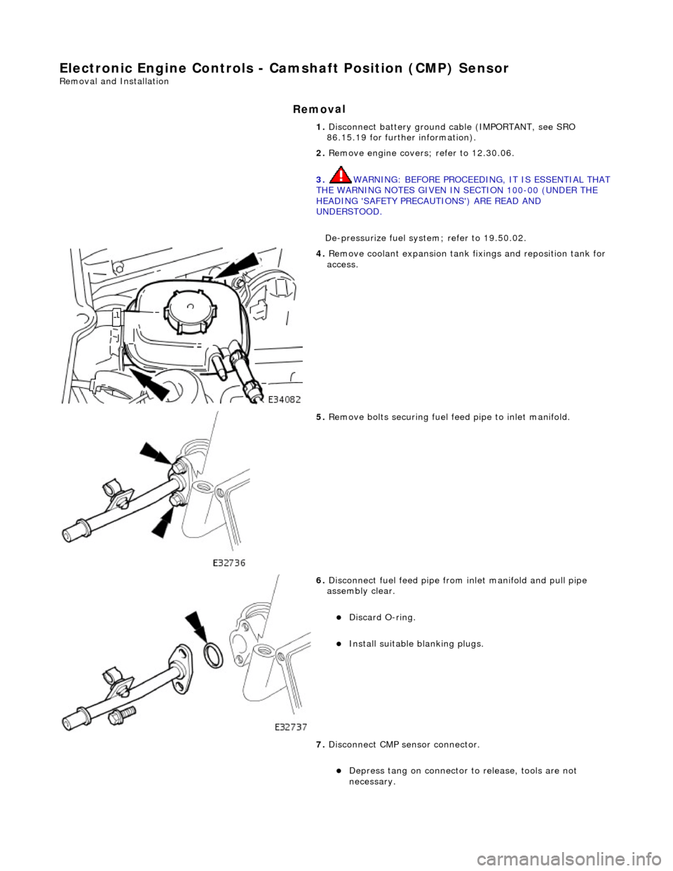
E
lectronic Engine Controls - Ca
mshaft Position (CMP) Sensor
Re
moval and Installation
Remov
al
1.
Disc
onnect battery ground cable (IMPORTANT, see SRO
86.15.19 for further information).
2. Remove engine covers ; refer to 12.30.06.
3. WARNING: BEFORE PROCEEDING, IT IS ESSENTIAL THAT
THE WARNING NOTES GIVEN IN SECTION 100-00 (UNDER THE
HEADING 'SAFETY PRECAUTIONS') ARE READ AND
UNDERSTOOD.
De-pressurize fuel system; refer to 19.50.02.
4. R
emove coolant expansion tank fixings and reposition tank for
access.
5. R
emove bolts securing fuel fe
ed pipe to inlet manifold.
6. Di
sconnect fuel feed pipe from inlet manifold and pull pipe
assembly clear.
Di
scard O-ring.
Inst
all suitable blanking plugs.
7. Disconnect CMP sensor connector.
De
press tang on connector to release, tools are not
necessary.