1998 JAGUAR X308 head lamp
[x] Cancel search: head lampPage 1978 of 2490
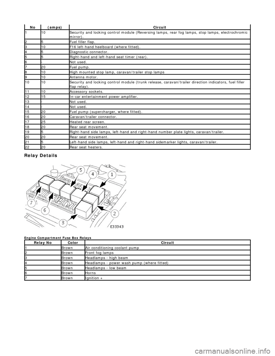
Relay Details
Engine Compartment Fuse Box Relays
No(amps)Circuit
110Security and locking control module (Reversing lamps, rear fog lamps, stop lamps, electrochromic
mirror).
25Fuel filler flap.
310F16 left-hand heelboard (where fitted).
45Diagnostic connector.
55Right-hand and left-han d seat timer (rear).
6-Not used.
720Fuel pump.
810High mounted stop lamp, caravan/trailer stop lamps
910Antenna motor.
1010Security and locking control module (trunk release, caravan/trailer direction indicators, fuel filler
flap relay).
1110Accessory sockets.
1215In-car entertainment power amplifier.
13-Not used.
14-Not used.
1520Fuel pump (supercharger, where fitted).
1620Caravan/trailer connector.
1725Heated rear screen.
1820Rear seat movement.
195Right-hand side lamps, left-h and and right-hand number pl ate lights, caravan/trailer.
2020Rear seat movement.
215Left-hand side lamps, left-hand and right-hand sidemarker lights, caravan/trailer.
2220Rear seat heaters.
Relay NoColorCircuit
1BrownAir conditioning coolant pump
2BrownFront fog lamps
3BrownHeadlamps - high beam
4BrownHeadlamps - power wash pump (where fitted)
5BrownHeadlamps - low beam
6BrownHorns
7BrownIgnition +
Page 2007 of 2490
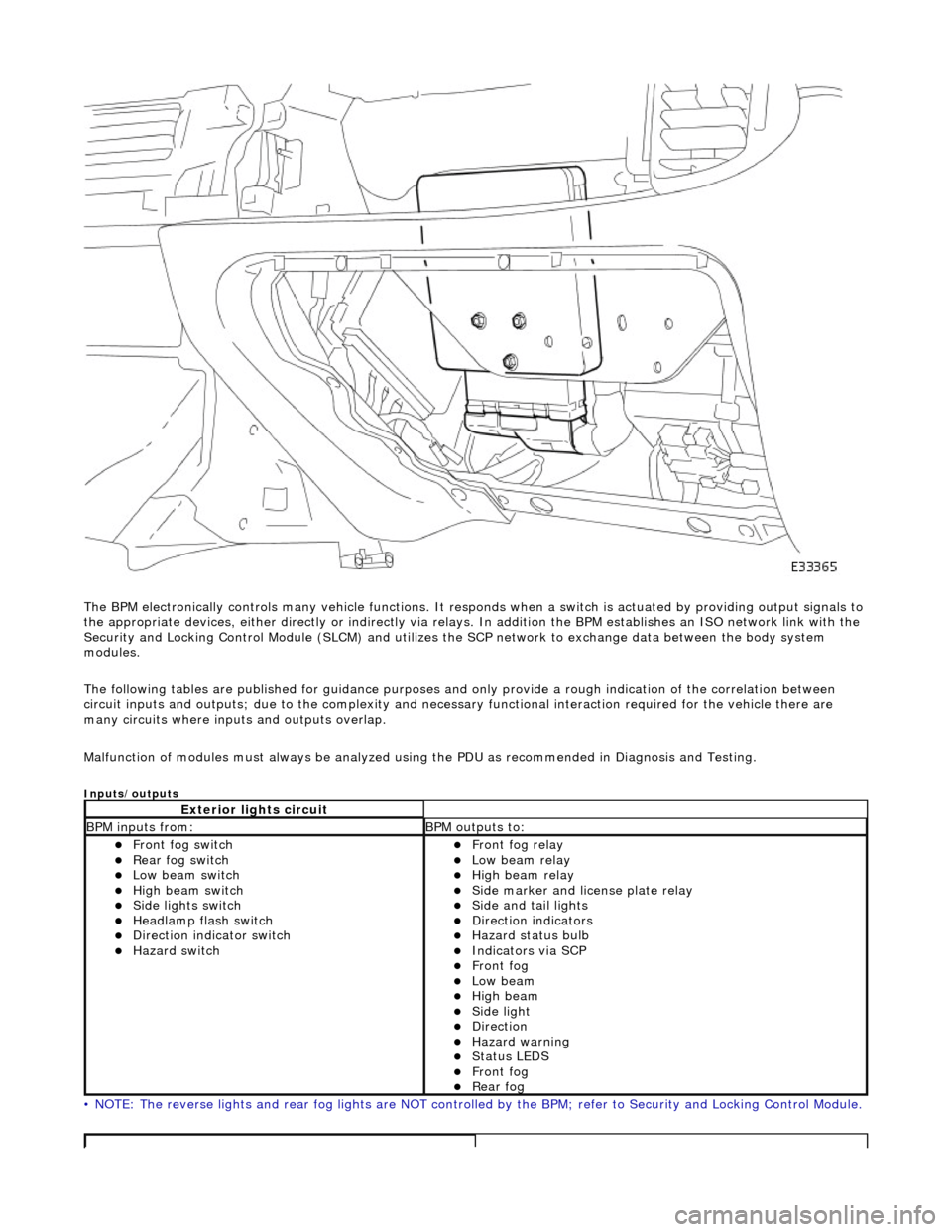
The BPM electronically controls many vehicle functions. It responds when a switch is actuated by providing output signals to
the appropriate devices, either di rectly or indirectly via relays. In addition the BPM establishes an ISO network link with the
Security and Locking Control Module (SLC M) and utilizes the SCP network to exchange data between the body system
modules.
The following tables are publis hed for guidance purposes and only provide a rough indication of the correlation between
circuit inputs and outputs; due to the complexity and necess ary functional interaction required for the vehicle there are
many circuits where inpu ts and outputs overlap.
Malfunction of modules must always be analyzed using the PDU as recommended in Diagnosis and Testing.
Inputs/outputs
• NOTE: The reverse lights and rear fog lights are NOT controlled by the BPM; refer to Security and Locking Control Module.
Exterior lights circuit
BPM inputs from: BPM outputs to:
Front fog switch Rear fog switch Low beam switch High beam switch Side lights switch Headlamp flash switch Direction indicator switch Hazard switch
Front fog relay Low beam relay High beam relay Side marker and license plate relay Side and tail lights Direction indicators Hazard status bulb Indicators via SCP Front fog Low beam High beam Side light Direction Hazard warning Status LEDS Front fog Rear fog
Page 2008 of 2490
Driver Door Module (DDM)
Interior lights circuit
BPM inputs from: BPM outputs to:
Header console courtesy light switch
SCPInstrument and switch illumination. Fade 1 (Header console courtesy lamps) Fade 2 (E-post courtesy lamps) Map lights Sun visor lamps Glovebox lamp Trunk lamps
Washer / wiper circuit
Wiper park switch Low screen wash switch Wiper slow speed switch Wiper fast speed switch Wiper intermittent switch Wash/wipe switch
Power wash relay Wiper motor run Screen wash pump Wiper fast/slow speed
Ignition circuit
Ignition position Auxiliary position Transit relay Mirror fold out Mirror fold flat
Central door locking circuit
Central locking button Valet switch SCP (door modules)
Central door locking relay SCP (door modules, security and locking control
module)
Sun roof ECU
Security system circuit
Hood security switch Horn switches Central locking button SCP (door modules, security and locking control
module)
ISO link (key transponder module)
Horn relay Active security sounder Passive security sounder Security status LED Central door locking relay SCP (door modules, security and locking control
module)
ISO link (key transponder module)
Steering column adjustment circuit
Column adjustment switchesColumn tilt motor Column reach motor
Gear shift interlock circuit
Neutral switch J-gate not in park Keylock solenoid Gearshift interlock solenoid
Seat heaters circuit
Seat heater switchesSeat heater relay Status LED
Seat buckle circuit
Seat buckleAudible warning SCP
Page 2032 of 2490
Front End Body Panels - Radiator Grille Opening Panel Reinforcement Removal and Installation
Removal
Installation
1.
Remove radiator grilles. Refer to 76.55.03.
2. Remove radiator grille surround. (Refer to 76.55.15)
3. Open hood.
4. Fit front fender cover.
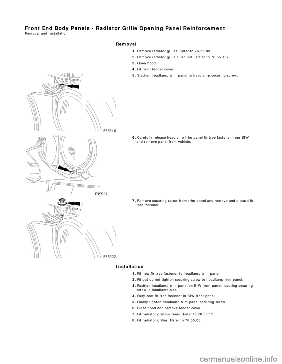
5. Slacken headlamp trim panel to headlamp securing screw.
6. Carefully release headlamp trim panel fir tree fastener from BIW
and remove panel from vehicle.
7. Remove securing screw from trim panel and remove and discard fir
tree fastener.
1. Fit new fir tree fastener to headlamp trim panel.
2. Fit but do not tighten securing screw to headlamp trim panel.
3. Position headlamp trim panel on BIW front panel, locating securing
screw in headlamp slot.
4. Fully seat fir tree fastener in BIW front panel.
5. Finally tighten headlamp trim panel securing screw.
6. Close hood and remove fender cover.
7. Fit radiator grill surround. Refer to 76.55.15
8. Fit radiator grilles. Refer to 76.55.03.
Page 2054 of 2490
Interior Trim and Ornamentation - Interior Trim
Description and Operation
Carpets
The passenger compartment carpet is a one piece moulded constr uction with integral sound deadening material, heel mats
and driver's footrest. The carpet is attach ed to the vehicle floor by plastic clips fitted below the door treadplates. Removal of the carpet necessitates re moval of the front seats, lifting of the centre console rear extens ion and removal of the heelboard
carpet.
Fascia
The full width, slush moulded, soft feel PVC fascia is mounted on an injection moulded armature and is faced with wood
veneer. In addition to the air conditioning and central, outer and demisting vents, it accepts instrument packs dedicated to
market requirements and a centrally mounted analogue clock.
Doors
The one-piece door casings are trimmed in UEV to match the seating, with wood veneer at the waistline and a carpet insert
at the front lower corner. Each casing is secured to the door inner panel by fir tree press fast eners along the lower section,
two armrest fixings at the centre and vene er panel dowels and fixings at the top. The armrests which are common to front
and rear doors, are trimmed in matching leather or UEV according to specification. The door switchpacks, dedicated to
driver and front or rear passenger, are in corporated in the armrests. A speaker is in stalled in the lower section of each door
and a tweeter is incorporated behind each interior door handle escutcheon. Where premium ICE is fitted, the front tweeters
are installed in the upper A posts.
A, B, C and D Posts
On each side,a grained UEV finisher trimmed to match the headlining is secured to the 'A' post and cantrail by fir tree
fasteners locating in BIW apertures. The upper 'D' post finisher is trimmed and secured in the same manner. The single
piece'B/C' post finishers, also finished in grained matching UEV, each have a front se at belt exit aperture and are secured to
the BIW by four spring clips and two fir tree fasteners.
Headlining
The one-piece headlining consists of a 6mm thick polyurethane foam membrane covered with suede effect knitted polyester. The headlining is secured to the BIW roof by body tangs, the roof console, sun visors, combined grab handles and coat
hooks, the cantrail finishers and where fitt ed, the sliding roof finisher and clips.
Trunk
Carpet covered trims line the trunk and are secured by fir tr ee fasteners to the sides and front inner panel. The carpet
covered, two-section, removable trunk fl oor provides access to the spare wheel and wheel changing equipment, the battery
and electrical carrier. The floor board rests on the spare wheel, with the front and rear edges locating in blocks on the fuel
tank backboard and the rear of the body. The support blocks provide for two floor he ight settings to accommodate either a
space saver or full size spare wheel.A moulded finisher covering the rear of the trunk below the sill is secured to the rear
panel by tabs and fir tree fasteners. Finish er panels fitted to the rear lamp units provide trunk interior access to the lamps.
The trunk lid underside is fitted with a removabl e moulded liner and two trunk illumination lights.
Page 2099 of 2490
Exterior Trim and Ornamentation - Exterior Trim
Description and Operation
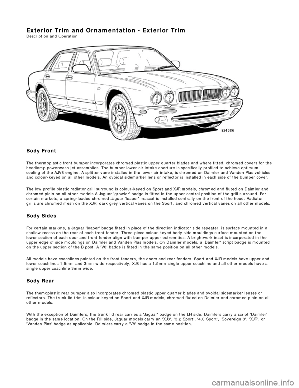
Body Front
The thermoplastic front bumper incorporates chromed plastic upper quarter blades and where fitted, chromed covers for the headlamp powerwash jet assemblie s. The bumper lower air intake aperture is specifically profiled to achieve optimum
cooling of the AJV8 engine. A splitter vane installed in the lowe r air intake, is chromed on Daimler and Vanden Plas vehicles
and colour-keyed on all other models. An ov oidal sidemarker lens or reflector is installed in each side of the bumper cover.
The low profile plastic radiator grill surround is colour-keyed on Sport and XJR mo dels, chromed and fluted on Daimler and
chromed plain on all other models .A Jaguar 'growler' badge is fitted in the upper central positi on of the grill surround. For
certain markets, a spring-loaded chromed Ja guar 'leaper' mascot is installed centrally on the front of the hood. Radiator
grills are chromed mesh on the XJR, dark grey vertical vanes on the Sport, and chromed ve rtical vanes on all other models.
Body Sides
For certain markets, a Jaguar 'l eaper' badge fitted in place of the direction indicator side re peater, is surface mounted in a
shallow recess on the rear of each fro nt fender. Three-piece colour-keyed body side mouldings surface mounted on the
lower section of each door and front fender align with bumper upper extremities. A brightwork inset is incorporated in the
upper edge of side mouldings on Daimler and Vanden Plas models. On Daimler models, a 'Daimler' script badge is mounted
on the upper section of the B post. A 'V8' badge is fitted in the same position on all other models.
All models have coachlines painted on th e front fenders, the doors and rear fender s. Sport and XJR models have upper and
lower coachlines 1.5mm an d 3mm wide respectively, XJ8 has a 1.5mm single upper coachline and all other models have a
single upper coachline 3mm wide.
Body Rear
The themoplastic rear bumper also inco rporates chromed plastic upper quarter blades and ovoi dal sidemarker lenses or
reflectors. The trunk lid trim is colour-keyed on Sport and XJ R models, chromed fluted on Daimler and chromed plain on all
other models.
With the exception of Daimlers, the trunk lid rear carries a 'Jaguar' badge on the LH side. Daimlers carry a script 'Daimler'
badge in the same location. On th e RH side, Jaguar models carry an 'XJ8', '3.2 Sport', '4.0 Sport', 'Sovereign 8', 'XJR', or
'Vanden Plas' badge as applic able. Daimlers carry a 'V8' badge in the same position.
Page 2274 of 2490
Remote Central Locking Transmitter Unit
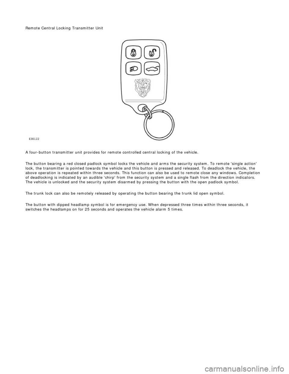
A four-button transmitter unit provides for remote controlled central locking of the vehicle.
The button bearing a red closed padlock sy mbol locks the vehicle and arms the security system. To remote 'single action'
lock, the transmitter is pointed towards the vehicle and this bu tton is pressed and released. To deadlock the vehicle, the
above operation is repeated with in three seconds. This function can also be used to remote close any windows. Completion
of deadlocking is indicated by an audible 'chirp' from the security system and a single flash from the direction indicators.
The vehicle is unlocked and the security system disarmed by pressing the button with the open padlock symbol.
The trunk lock can also be remotely released by op erating the button bearing the trunk lid open symbol.
The button with dipped headlamp symbol is for emergency us e. When depressed three times within three seconds, it
switches the headlamps on for 25 seconds and operates the vehicle alarm 5 times.
Page 2307 of 2490
cooling duct.
The windshield washer is operated by pressing the button at the end of the wiper control stalk switch. Pressing and
releasing the button operates the washer for 1 to 1.4 seconds and the wiper completes three sweeps. An optional drip wipe
function adds a further sweep of the wiper after a 4 second delay, to clear residual fluid from the windshield. If the button is
held depressed, the washer and wiper will operate continuous ly for up to 20 seconds. When the button is released, the
wiper will again complete three further sweeps.
Headlamp Powerwash
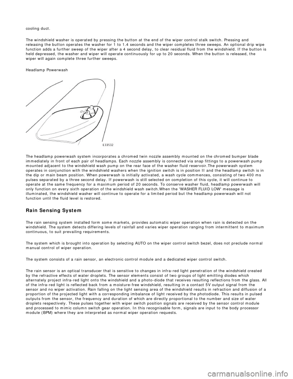
The headlamp powerwash system incorporates a chromed twin nozzle assembly mounted on the chromed bumper blade
immediately in front of each pair of he adlamps. Each nozzle assembly is connected via snap fittings to a powerwash pump
mounted adjacent to the windshield wash pump on the rear face of the washer fluid reservoir.The powerwash system
operates in conjunction with the windshield washers when the ignition switch is in position II and the headlamp switch is in
the dip or main beam position. When powerwash is initially activated, a wash cycle commences, consisting of two 400 ms
pulses separated by a three second delay. If powerwash is still selected on completion of this cycle, it will continue to
operate at the same frequency for a maximum period of 20 se conds. To conserve washer fluid, headlamp powerwash will
only function on every sixth operation of the windshie ld wash switch.When the 'WASHER FLUID LOW' message is
illuminated, the windshield washer will continue to operat e for a limited period but the headlamp powerwash will not
function until the fluid level is restored.
Rain Sensing System
The rain sensing system installed form so me markets, provides automatic wiper operation when rain is detected on the
windshield. The system detects differing le vels of rainfall and varies wiper operation ranging from intermittent to maximum
continuous, to suit prevailing requirements.
The system which is brought into operation by selecting AUTO on the wiper control switch bezel, does not preclude normal
manual control of wiper operation.
The system consists of a rain sensor, an electronic control module and a dedicated wiper control switch.
The rain sensor is an optical transducer that is sensitive to changes in infra-red light penetration of the windshield created
by the refractive effects of water drople ts. The sensor elements consist of two groups of light emitting diodes which
alternately project infra-red light onto th e windshield and a photo-diode that receiv es resulting reflections from the glass. A ll
of the infra-red light is reflected back from a moisture-free windshield, resulting in a contact 5V output signal from the
sensor and no wiper activation. Rain falling on the light sensing area of the wi ndshield results in refraction and diffusion of a
proportion of the projected light with a corresponding imbalance of light received by the photodiode. This results in pulsed
outputs from the sensor, the frequency and duration of which are directly proportional to the number and size of water
droplets respectively. These pulses together with wiper switch position signals are received by the sensor control module
and processed to mimic column switch gear operation. In this recognisable form, signals are input to the body processor
module (BPM) where they are interprete d as normal wiper operation requests.