Page 1918 of 2490
Exterior Lighting -
Bulbs
Torques
DescriptionCapacityType
Flasher Side Repeater12V 5WCapless Long Life
Fog Lamp - Front12V 51WHalogen HB4 Long Life
Fog Lamp - Rear Guard12V 21WP21W, Bayonet Long Life
Front Direction Indicator12V 21WBayonet Amber Long Life
Front Parking (side) Lamp12V 5WCapless Long Life
Headlamp - Main12V 55WHalogen H7
Headlamp - Dip12V 55WHalogen H7
High Mounted Stop Lamp12V 5WCapless Long Life
License Plate Lamp12V 5WFestoon Long Life
Rear Direction Indicator12V 21WPY21W, Bayonet Amber Long Life
Reverse Lamp12V 21WP21W, Bayonet Long Life
Side Marker Lamp12V 5WCapless Long Life
Stop/Tail Lamp12V 21/5WTwin Filament Bayonet Long Life
ComponentNm
Rear Lamp Assembly to Body3
Page 1919 of 2490

Exterior Lighting - Exterior Lighting
Description and Operation
A multi-function switch located on the left stalk of the steering column switch assembly permits selection of either parking
(side), headlamps, auto-headlamp or off. Selection of a particular mode provides the appropriate input to the body
processor module (BPM).
Where the auto headlamp function is incorporated, a light sensor in the interior rear view mirror monitors ambient light and
provides an input to the BPM. The BPM responds by switching the low beam headlamps on or off as appropriate for the
prevailing light conditions.
The front and rear fog lamp switch is located on the fascia outboard of the steering column.
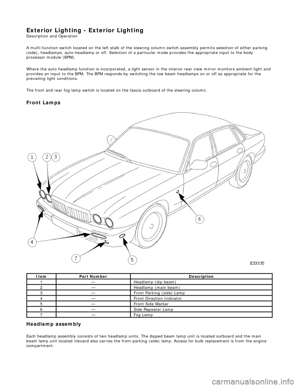
Front Lamps
Headlamp assembly
Each headlamp assembly consists of tw o headlamp units. The dipped beam lamp unit is located outboard and the main
beam lamp unit located inboard also carries the front parking (side) lamp. Access for bulb replacement is from the engine
compartment.
ItemPart NumberDescription
1—Headlamp (dip beam)
2—Headlamp (main beam)
3—Front Parking (side) Lamp
4—Front Direction Indicator
5—Front Side Marker
6—Side Repeater Lamp
7—Fog Lamp
Page 1933 of 2490
Exterior Lighting - Headlamp Assembly
Removal and Installation
Removal
1. Remove radiator grill. Refer to 76.55.03.
2. Remove radiator grill surro und. Refer to 76.55.15.
3. Remove headlamp trim panel. Refer to 76.11.23.
4. Disconnect headlamp levelling actuator if fitted.
5. Disconnect headlamp assembly harness connector.
6. Remove headlamp assembly to body lower nuts.
7. Remove headlamp to body upper nuts.
Page 1934 of 2490
Installation
8. Remove headlamp assembly from vehicle.
1. Position headlamp assembly on body and install upper nuts.
2. Install headlamp to body lower nuts.
3. Connect headlamp assembly harness connector.
4. Connect headlamp levelling actuator harness connector if
fitted.
Page 1935 of 2490
5. Align headlamp beams.
6. Install headlamp trim panel. Refer to 76.11.23.
7. Install radiator grill surround. Refer to 76.55.15.
8. Install radiator gril l. Refer to 76.55.03.
Page 1936 of 2490
Exterior Lighting - Headlamp Leveling Motor
Removal and Installation
Removal
Installation
1. Disconnect harness multiplug from headlamp levelling
actuator.
2. Rotate actuator 1/4 turn inwards, tilt forward end downward
and withdraw assembly from headlamp.
1. With forward end tilted downward , position actuator assembly
on headlamp.
2. Align actuator with headlamp an d rotate it 1/4 turn outwards
to engage and fully seat.
3. Connect harness multiplug to actuator.
4. Carry out headlamp beam al ignment to the appropriate
alignment equipment instructions.
Page 1937 of 2490
Exterior Lighting - High Beam Headlamp
Removal and Installation
Removal
Installation
1. Remove headlamp assembly fo r access. Refer to 86.41.33.
2. Release bulb holder securing tangs and position holder for
access.
3. Rotate pilot bulb holder 1/4 turn and withdraw holder.
4. Invert headlamp assembly.
5. Release headlamp unit adju sting screws and pivot.
1. Install headlamp unit on adjusting screw and pivot seats.
Page 1938 of 2490
2. Invert headlamp assembly.
3. Install pilot bulb holder in headla mp unit and rotate 1/4 turn to
secure.
4. Install headlamp assembly bulb holder.
5. Install headlamp assembly. Refer to 86.41.33.
6. Align headlamp beams.