Page 1375 of 2490
Automatic Transmission/Transaxle - 4.0L NA V8 - AJ27/3.2L NA V8 - AJ26
- Transmission
Removal
Removal
Special Tool(s)
Engine support
303-021
Engine lifting brackets
303-536
1. Select N gear position.
2. Open the engine compartment and fit paintwork protection
sheets.
3. Disconnect battery ground cable.
Remove the battery cover.
4. Remove the engine covers (12.30.06).
5. Remove the air intake tube, MAFM and air cleaner cover assy,
(19.10.30).
6. Install engine lifting bracket 303 - 536 at the rear RH.
7. Reposition the coolant he ader tank for access.
1. Remove the securing bolt.
Page 1381 of 2490
Automatic Transmission/Transaxle - 4.0L NA V8 - AJ27/3.2L NA V8 - AJ26
- Input Shaft Seal
Disassembly and Assembly of Subassemblies
Special Tool(s)
Oil seal replacer
307-357
1. Remove the transmission unit, 44.20.01.
2. Remove the torque converter from the transmission unit,
44.17.07.
3. Remove the front pump seal.
Remove and discard the seal retaining snap-ring.
Using a 'Snap-on' oil seal puller, remove and discard the
seal.
4. Clean the seal housing.
5. Installation is th e reverse of the re moval procedure.
6. Use tool 307 - 357 to install the seal.
Lubricate the seal pr ior to fitting.
Page 1382 of 2490

Automatic Transmission/Transaxle - 4.0L NA V8 - AJ27/3.2L NA V8 - AJ26
- Torque Converter
Disassembly and Assembly of Subassemblies
Special Tool(s)
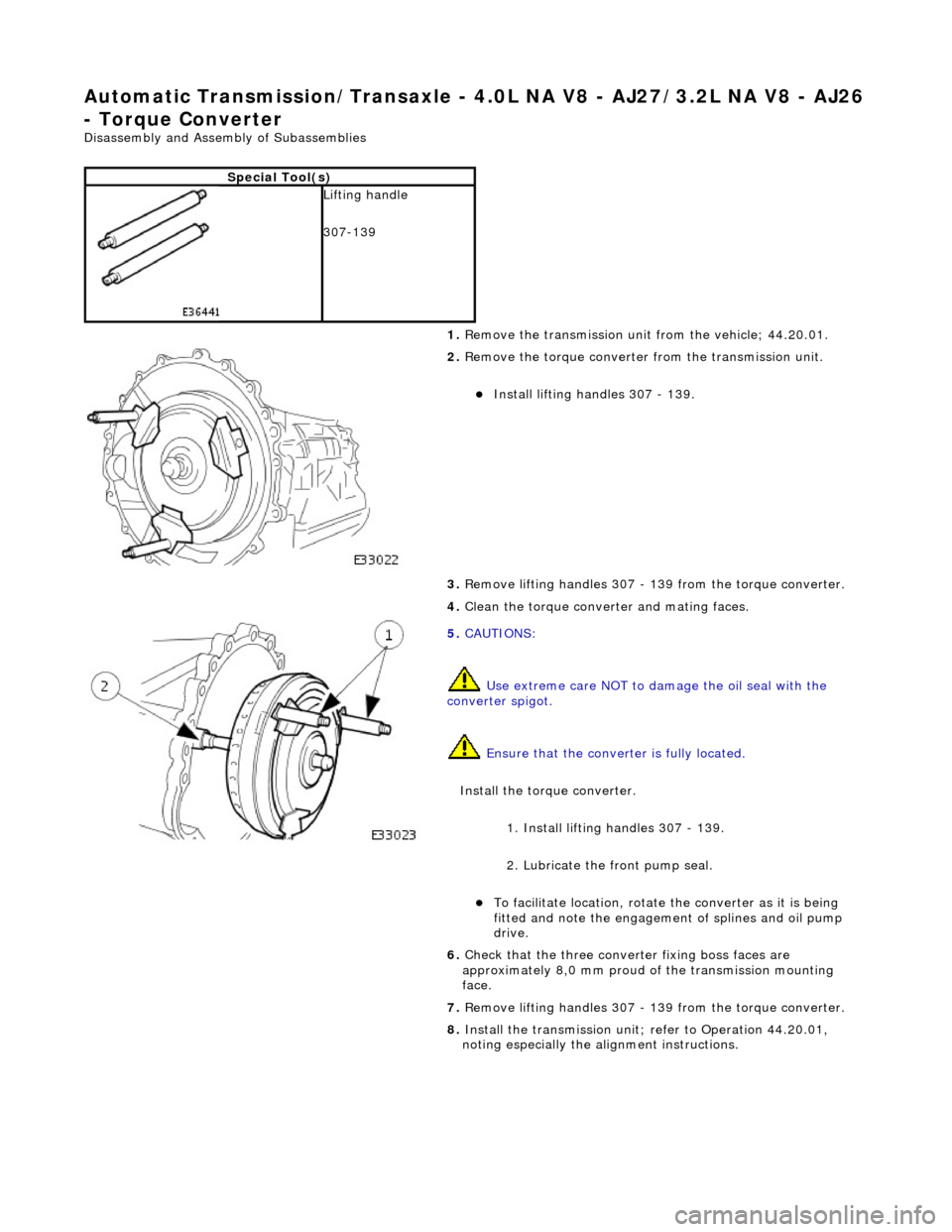
Lifting handle
307-139
1. Remove the transmission unit from the vehicle; 44.20.01.
2. Remove the torque converter from the transmission unit.
Install lifting handles 307 - 139.
3. Remove lifting handles 307 - 139 from the torque converter.
4. Clean the torque conver ter and mating faces.
5. CAUTIONS:
Use extreme care NOT to damage the oil seal with the
converter spigot.
Ensure that the conver ter is fully located.
Install the torque converter.
1. Install lifting handles 307 - 139.
2. Lubricate the front pump seal.
To facilitate location, rotate the converter as it is being
fitted and note the engagement of splines and oil pump
drive.
6. Check that the three conver ter fixing boss faces are
approximately 8,0 mm proud of the transmission mounting
face.
7. Remove lifting handles 307 - 139 from the torque converter.
8. Install the transmission unit; refer to Operation 44.20.01,
noting especially the alignment instructions.
Page 1383 of 2490
Automatic Transmission/Transaxle - 4.0L NA V8 - AJ27/3.2L NA V8 - AJ26
- Transmission
Installation
Installation
Special Tool(s)
Engine support
303-021
Engine lifting brackets
303-536
1. Clean all mating faces and relevant parts.
2. Apply lubricant, Molycote or equivalent, to the spigot of the
torque converter.
3. Align the engine drive plate.
1. Rotate the crankshaft to position the ORANGE dot
within the indicated sector.
• NOTE: Viewed from the rear of the vehicle.
2. Keeping the dot within the sector, align the nearest converter fixing hole to the access aperture.
4. Align the torque converter
1. Rotate the converter to position the BLUE dot within the indicated sector.
2. Keeping the dot within the sector, align the nearest fixing boss as indicated, so that when the two units
are mated, the converter need only be moved the
minimum amount.
Page 1388 of 2490

Automatic Transmission/Transaxle - 4.0L SC V8 - AJ26 -
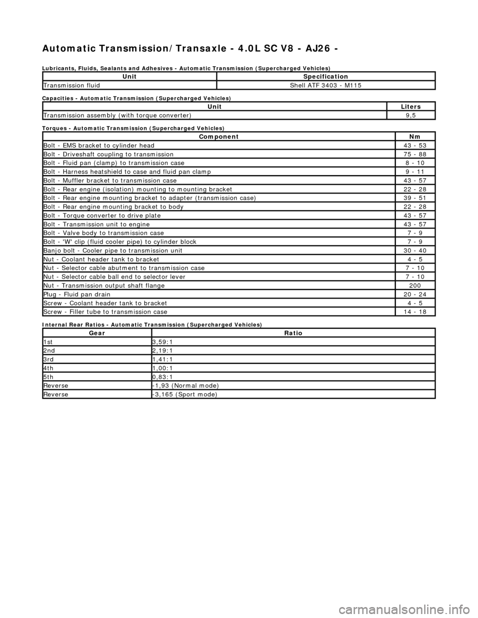
Lubricants, Fluids, Sealants and Adhesives - Automatic Transmission (Supercharged Vehicles)
Capacities - Automatic Transmission (Supercharged Vehicles)
Torques - Automatic Transmission (Supercharged Vehicles)
Internal Rear Ratios - Automatic Transmission (Supercharged Vehicles)
UnitSpecification
Transmission fluidShell ATF 3403 - M115
UnitLiters
Transmission assembly (with torque converter)9,5
ComponentNm
Bolt - EMS bracket to cylinder head43 - 53
Bolt - Driveshaft coupling to transmission75 - 88
Bolt - Fluid pan (clamp) to transmission case8 - 10
Bolt - Harness heatshield to case and fluid pan clamp9 - 11
Bolt - Muffler bracket to transmission case43 - 57
Bolt - Rear engine (isolation) mounting to mounting bracket22 - 28
Bolt - Rear engine mounting brac ket to adapter (transmission case)39 - 51
Bolt - Rear engine mounting bracket to body22 - 28
Bolt - Torque converter to drive plate43 - 57
Bolt - Transmission unit to engine43 - 57
Bolt - Valve body to transmission case7 - 9
Bolt - 'W' clip (fluid cooler pipe) to cylinder block7 - 9
Banjo bolt - Cooler pipe to transmission unit30 - 40
Nut - Coolant header tank to bracket4 - 5
Nut - Selector cable abutment to transmission case7 - 10
Nut - Selector cable ball end to selector lever7 - 10
Nut - Transmission output shaft flange200
Plug - Fluid pan drain20 - 24
Screw - Coolant header tank to bracket4 - 5
Screw - Filler tube to transmission case14 - 18
GearRatio
1st3,59:1
2nd2,19:1
3rd1,41:1
4th1,00:1
5th0,83:1
Reverse-1,93 (Normal mode)
Reverse-3,165 (Sport mode)
Page 1389 of 2490
Automatic Transmission/Transaxle - 4.0L SC V8 - AJ26 - Transmission
Description
Description and Operation
Transmission Assembly
This electronically controlled five speed unit is unique to supercharged vehicles.
Introduction
Parts List
Transmission Fluid
It is not necessary to change the transmis sion fluid in normal service; routine level checking is not required. The sealed
dipstick tube is fitted for service requir ements only, with a dipstick being availa ble as a special tool and NOT fitted as
standard.
Components and Functions
Transmission Casing
The following components are housed within the casing;
ItemPart NumberDescription
1—Torque converter housing
2—Breather
3—Transmission casing
4—Drive flange (output shaft)
5—Fluid pan
6—Selector lever
Page 1400 of 2490

Automatic Transmission/Transaxle - 4.0L SC V8 - AJ26 - Diagnostic
Strategy
Diagnosis and Testing
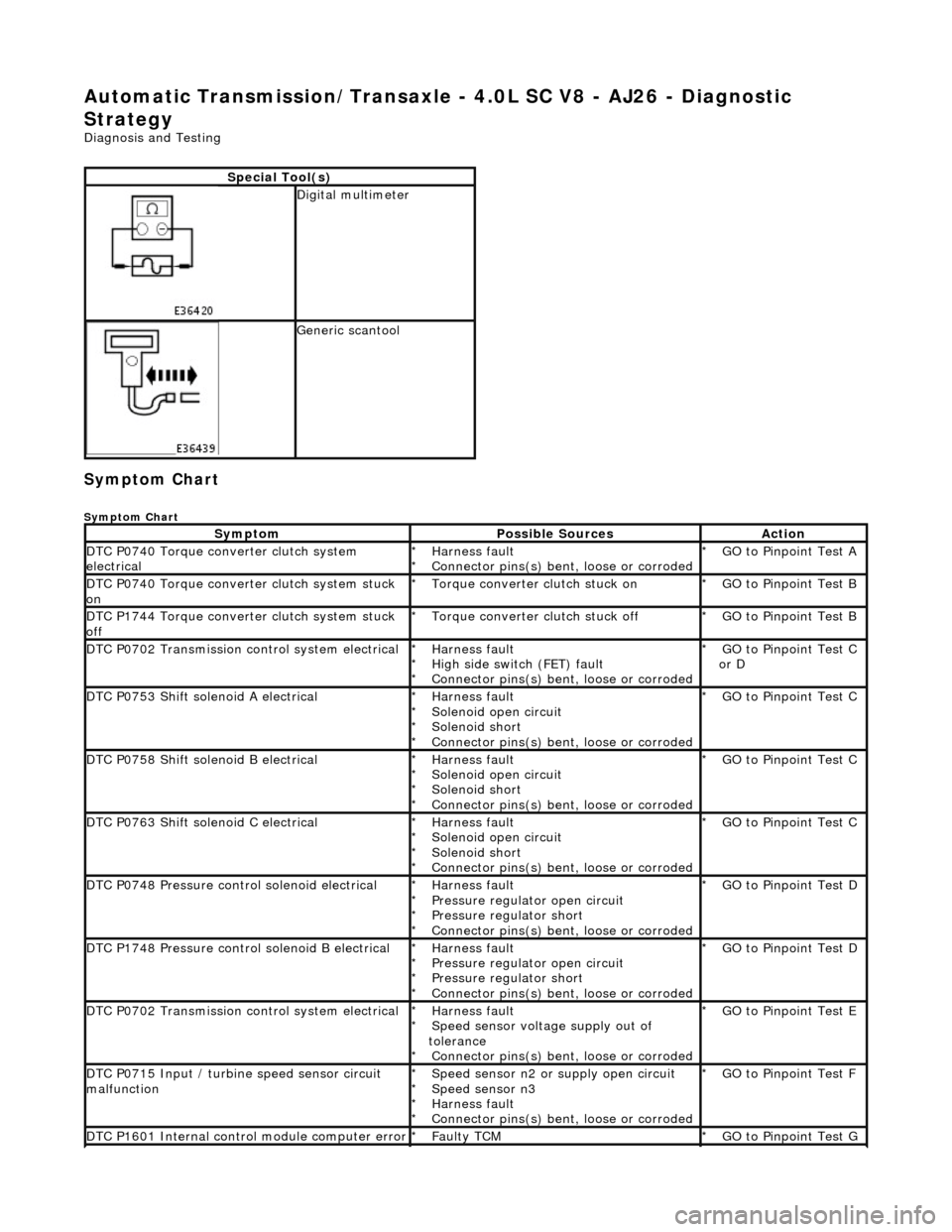
Symptom Chart
Symptom Chart
Special Tool(s)
Digital multimeter
Generic scantool
SymptomPossible SourcesAction
DTC P0740 Torque converter clutch system
electricalHarness fault
Connector pins(s) bent , loose or corroded
*
*GO to Pinpoint Test A
*
DTC P0740 Torque converter clutch system stuck
onTorque converter clutch stuck on
*GO to Pinpoint Test B
*
DTC P1744 Torque converter clutch system stuck
offTorque converter clutch stuck off
*GO to Pinpoint Test B
*
DTC P0702 Transmission control system electricalHarness fault
High side switch (FET) fault
Connector pins(s) bent , loose or corroded
*
*
*GO to Pinpoint Test C
or D
*
DTC P0753 Shift solenoid A electricalHarness fault
Solenoid open circuit
Solenoid short
Connector pins(s) bent
, loose or corroded
*
*
*
*GO to Pinpoint Test C *
DTC P0758 Shift solenoid B electricalHarness fault
Solenoid open circuit
Solenoid short
Connector pins(s) bent
, loose or corroded
*
*
*
*GO to Pinpoint Test C *
DTC P0763 Shift solenoid C electricalHarness fault
Solenoid open circuit
Solenoid short
Connector pins(s) bent
, loose or corroded
*
*
*
*GO to Pinpoint Test C *
DTC P0748 Pressure control solenoid electricalHarness fault
Pressure regulator open circuit
Pressure regulator short
Connector pins(s) bent
, loose or corroded
*
*
*
*GO to Pinpoint Test D *
DTC P1748 Pressure control solenoid B electricalHarness fault
Pressure regulator open circuit
Pressure regulator short
Connector pins(s) bent
, loose or corroded
*
*
*
*GO to Pinpoint Test D *
DTC P0702 Transmission control system electricalHarness fault
Speed sensor voltage supply out of
tolerance Connector pins(s) bent , loose or corroded
*
*
*GO to Pinpoint Test E
*
DTC P0715 Input / turbine speed sensor circuit
malfunctionSpeed sensor n2 or supply open circuit
Speed sensor n3
Harness fault
Connector pins(s) bent , loose or corroded
*
*
*
*GO to Pinpoint Test F
*
DTC P1601 Internal control module computer errorFaulty TCM
*GO to Pinpoint Test G *
Page 1429 of 2490
Automatic Transmission/Transaxle - 4.0L SC V8 - AJ26 - Transmission
Fluid Drain and Refill
General Procedures
Special Tool(s)
Dipstick
307-379
1. Disconnect the battery ground lead.
2. Raise the vehicle for access.
3. NOTE: This procedure will not re move residual fluid from the
torque converter.
Drain the transmission fluid.
3. WARNING: TRANSMISSION FLUID MAY CAUSE
SEVERE BURNS, ENSURE THAT ALL SAFETY PROCEDURES
ARE OBSERVED AND THAT THE RECEPTACLE FOR WASTE
HAS SUFFICIENT CAPACITY.
Carefully remove the drain pl ug and discard the sealing
washer.
4. Refit the drain plug and tighten to the specified torque figure.
Use a new sealing washer.
5. Connect the PDU to monitor the fluid temperature.
6. Access the dipstick tube.
1. Break off the dipstick tube plug locking plate.
2. Push the locking pin downward, into the plug.
3. Remove the dipstick tube plug.
Push the locking pin through the tube plug and discard the
pin.