Page 1671 of 2490
F
it the front muffler fully into
the intermediate mufflers.
2. Con
nect the front muffler flanges to the catalytic converters.
F
it a new gasket to each flange.
Con
nect the front muffler flanges to the catalytic
converters; move the front muffler / intermediate
mufflers assembly forwards.
Tigh
ten the flange nuts (left-hand and right-hand sides),
front muffler to catalytic converters.
3. F
it the bolts which secure the front muffler rear mounting to
the rear of the gearbox.
4. Re
position the intermediate mu
fflers to the front muffler to
align the correct referenc e / index indicator ring.
Ti
ghten the clamps (left-han
d and right-hand sides),
intermediate mufflers to front muffler.
5. Lower the ramp.
Page 1673 of 2490
I
nstallation
7.
Clean and inspect al l e
xhaust joints.
1. Fi
t the intermediate muffler assembly.
F
it the muffler assembly to the axle carrier and to the
over-axle mounting rubber.
2. Locate the intermedi
ate muffl
er to the front muffler.
3. Cor
rectly position the front muffl
er in the catalytic converters
to align the correct reference / index indicator ring..
Tigh
ten the clamps (left-hand
and right-hand sides), front
muffler to catalytic converters.
4. Correctly position the intermedia te muffler at the front muffler
to align the correct reference / index indicator ring..
Tigh
ten the clamp, intermediate
mufflers to front muffler.
Page 1676 of 2490
2. Locate the intermediate muffl er to the front muff
ler.
3. Cor r
ectly position the intermedia
te muffler at the front muffler
to align the correct refere nce / index indicator ring.
Tighte
n the clamp, intermediate
muffler to front muffler.
4. NO TE
: If necessary, loosen and rotate the intermediate
muffler, at the front to intermediate muffler joint, to achieve the
tailpipe trim settings. Refer to Specifications in this section.
Correctly position the rear muffler assembly.
Connect the rear muffl
er to the intermediate muffler and
insert to the Nominal indicator ring, rotating back and
forth to aid engagement.
Chec k
that the mounting is located correctly into the
mounting rubber.
Chec k
that the tailpi
pe position is wi thin the specified
settings, adjusting engageme nt within the Maximum and
Minimum indicator rings if necessary. Refer to
Specifications in this section.
5. Tighten the securing clamp, in termediate muffler to rear
muffler.
Page 1679 of 2490
I
nstallation
7.
Clean and inspect al l e
xhaust joints.
1. Fi
t the intermediate muffler assembly.
F
it the muffler assembly to the axle carrier and to the
over-axle mounting rubber.
2. Locate the intermedi
ate muffl
er to the front muffler.
3. Cor
rectly position the front muffl
er in the catalytic converters
to align the correct reference / index indicator ring..
Tigh
ten the clamps (left-hand
and right-hand sides), front
muffler to catalytic converters.
4. Correctly position the intermedia te muffler at the front muffler
to align the correct reference / index indicator ring..
Tigh
ten the clamp, intermediate
mufflers to front muffler.
Page 1682 of 2490
2. Locate the intermediate muffl er to the front muff
ler.
3. Cor r
ectly position the intermedia
te muffler at the front muffler
to align the correct refere nce / index indicator ring.
Tighte
n the clamp, intermediate
muffler to front muffler.
4. NO TE
: If necessary, loosen and rotate the intermediate
muffler, at the front to intermediate muffler joint, to achieve the
tailpipe trim settings. Refer to Specifications in this section.
Correctly position the rear muffler assembly.
Connect the rear muffl
er to the intermediate muffler and
insert to the Nominal indicator ring, rotating back and
forth to aid engagement.
Chec k
that the mounting is located correctly into the
mounting rubber.
Chec k
that the tailpi
pe position is wi thin the specified
settings, adjusting engageme nt within the Maximum and
Minimum indicator rings if necessary. Refer to
Specifications in this section.
5. Tighten the securing clamp, in termediate muffler to rear
muffler.
Page 1744 of 2490

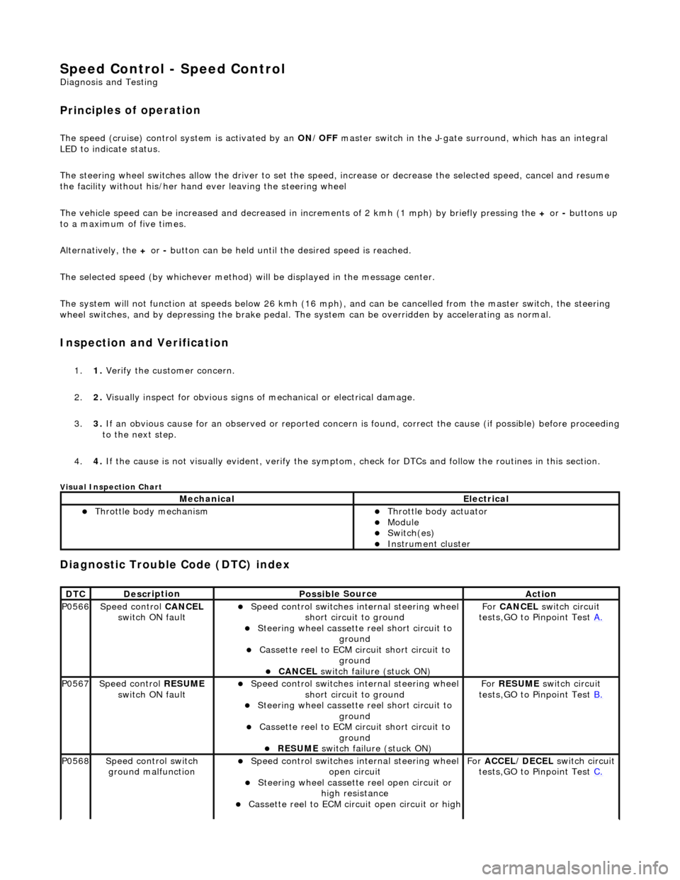
Speed Control - Speed
Control
D
iagn
osis and Testing
Pri
n
ciples of operation
The s
p
eed (cruise) control sy
stem is activated by an ON/OFF master switch in the J-gate surround, which has an integral
LED to indicate status.
The steering wheel switches allow the driver to set the speed, increase or decrease the selected speed, cancel and resume
the facility without his/her hand ever leaving the steering wheel
The vehicle speed can be increased an d decreased in increments of 2 kmh (1 mph) by briefly pressing the + or - buttons up
to a maximum of five times.
Alternatively, the + or - button can be held until th e desired speed is reached.
The selected speed (by whichever method) w ill be displayed in the message center.
The system will not function at speeds below 26 kmh (16 mph), and can be cancelled from the master switch, the steering
wheel switches, and by depressing th e brake pedal. The system can be overridden by accelerating as normal.
In
spection and Verification
1.
1. Veri fy the customer concern.
2. 2. Vis
ually inspect for obvious signs of mechanical or electrical damage.
3. 3. If an obvious cause for an observed or reported concern is found, correct the cause (if possible) before proceeding
to the next step.
4. 4. If the cause is not visually evident, verify the symptom, check for DTCs and follow the routines in this section.
Vi
sual Inspection Chart
Diagnostic Trouble Code (D
TC) index
MechanicalElectrical
Throttle body mechan
ism
Throttle body actuator
Module Switch(es) Instrument cluster
DTC
De
scr
iption
Possib
l
e Source
Acti
o
n
P0566Speed
c
ontrol
CANCEL
switch ON fault
Speed
control switches internal steering wheel
short circuit to ground
St
eering wheel cassette reel short circuit to
ground
Cassette reel to ECM circ
uit short circuit to
ground
CANCEL
switch failure (stuck ON)
Fo
r
CANCEL switch circuit
tests,GO to Pinpoint Test A.
P0567Speed c
ontrol
RESUME
switch ON fault
Speed
control switches internal steering wheel
short circuit to ground
St
eering wheel cassette reel short circuit to
ground
Cassette reel to ECM circ
uit short circuit to
ground
RESUME swit
ch failure (stuck ON)
For
RESUME switch circuit
tests,GO to Pinpoint Test B.
P0568Spee
d control switch
ground malfunction
Speed
control switches internal steering wheel
open circuit
St
eering wheel cassette reel open circuit or
high resistance
Cassette reel to ECM ci
rcuit open circuit or high
For
ACCEL/DECEL switch circuit
tests,GO to Pinpoint Test C.
Page 2329 of 2490

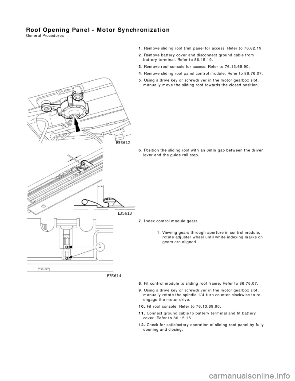
Roof Opening Panel - Motor Synchronization
General Procedures
1.
Remove sliding roof trim panel for access. Refer to 76.82.19.
2. Remove battery cover and disc onnect ground cable from
battery terminal. Refer to 86.15.19.
3. Remove roof console for ac cess. Refer to 76.13.69.90.
4. Remove sliding roof panel cont rol module. Refer to 86.76.07.
5. Using a drive key or screwdriver in the motor gearbox slot,
manually move the sliding roof towards the closed position.
6. Position the sliding roof with an 8mm gap between the driven
lever and the guide rail step.
7. Index control module gears.
1. Viewing gears through aperture in control module, rotate adjuster wheel until white indexing marks on
gears are aligned.
8. Fit control module to sliding r oof frame. Refer to 86.76.07.
9. Using a drive key or screwdriver in the motor gearbox slot,
manually rotate the spindle 1/4 turn counter-clockwise to re-
engage the motor drive.
10. Fit roof console. Refer to 76.13.69.90.
11. Connect ground cable to batt ery terminal and fit battery
cover. Refer to 86.15.15.
12. Check for satisfactory operation of sliding roof panel by fully
opening and closing.