1998 JAGUAR X308 turn signal
[x] Cancel search: turn signalPage 1030 of 2490
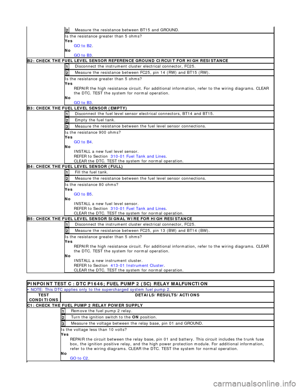
Measure t
he resistance
between BT15 and GROUND.
2
Is the res
istance greater than 5 ohms?
Yes GO to B2
.
No
GO to B3
.
B2: CHECK THE FUEL
LEVEL SENSOR REFERE
NCE GROUND CIRCUIT FOR HIGH RESISTANCE
Disc
onnect the instrument cluster electrical connector, FC25.
1
Meas
ure t
he resistance between FC25, pin 14 (RW) and BT15 (RW).
2
Is the res
istance greater than 5 ohms?
Yes REPAIR the high resistance circui t. For additional information, refer to the wiring diagrams. CLEAR
the DTC. TEST the system for normal operation.
No GO to B3
.
B3: CHECK THE FUEL
LEVEL SENSOR (EMPTY)
Di
sc
onnect the fuel level sensor electrical connectors, BT14 and BT15.
1
Empty the fuel
tank. 2
Measure t
he resistance between the
fuel level sensor connections.
3
Is t
he resistance 900 ohms?
Yes GO to B4
.
No
INST
ALL a new fuel level sensor.
REFER to Section 310
-0 1
Fuel Tank and Lines
.
CLEAR t h
e DTC. TEST the system for normal operation.
B4:
CHECK
THE FUEL LEVEL SENSOR (FULL)
Fi
ll
the fuel tank.
1
Meas
ure t
he resistance between the
fuel level sensor connections.
2
Is
the resistance 80 ohms?
Yes GO to B5
.
No
INST
ALL a new fuel level sensor.
REFER to Section 310
-0 1
Fuel Tank and Lines
.
CLEAR t h
e DTC. TEST the system for normal operation.
B
5
: CHECK THE FUEL LEVEL SENSOR SIGNAL WIRE FOR HIGH RESISTANCE
Di
sc
onnect the instrument cluster electrical connector, FC25.
1
Meas
ure t
he resistance between FC25, pin 13 (BW) and BT14 (BW).
2
Is th
e res
istance greater than 5 ohms?
Yes REPAIR the high resistance circui t. For additional information, refer to the wiring diagrams. CLEAR
the DTC. TEST the system for normal operation.
No INSTALL a new instrument cluster.
REFER to Section 413
-01
Instrume
nt Cluster
.
CLEAR t h
e DTC. TEST the system for normal operation.
P
INPOINT TEST C : DTC P1646; FU
EL PUMP 2 (SC) RELAY MALFUNCTION
•
NO
TE: This DTC applies only to the
supercharged system fuel pump 2.
TES
T
CONDITIONS
D E
TAILS/RESULTS/ACTIONS
C
1
: CHECK THE FUEL PUMP 2 RELAY POWER SUPPLY
R
e
move the fuel pump 2 relay.
1
Turn the ignition swi
t
ch to the
ON position.
2
Meas
ure t
he voltage between the
relay base, pin 01 and GROUND.
3
Is the volt
age less than 10 volts?
Yes REPAIR the circuit between the rela y base, pin 01 and battery. This circuit includes the trunk fuse
box, the ignition positive relay, and the high power protection module. For additional information,
refer to the wiring diagrams. CLEAR the DTC. TEST the system for normal operation.
No GO to C2
.
Page 1067 of 2490
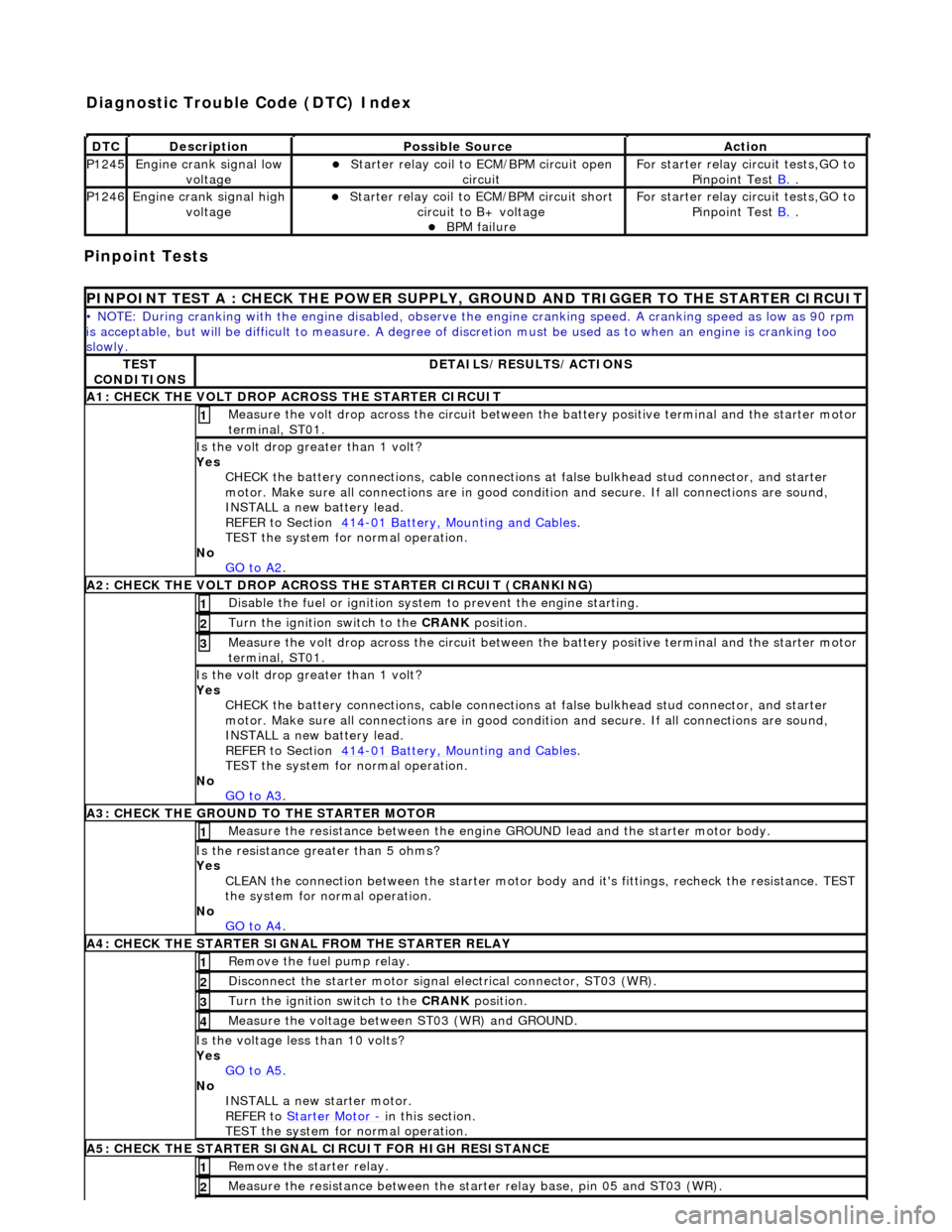
Pinpoint Tests
DT
C
De
scription
Possib
le Source
Acti
on
P1245Engine
crank signal low
voltage
Starter relay
coil to
ECM/BPM circuit open
circuit
F
or starter relay circuit tests,GO to
Pinpoint Test B.
.
P1246Engine
crank signal high
voltage
Starter relay
coil to ECM/BPM circuit short
circuit to B+ voltage
B
PM failure
F
or starter relay circuit tests,GO to
Pinpoint Test B.
.
P
INPOINT TEST A : CHECK THE
POWER SUPPLY, GROUND AND TRI GGER TO THE STARTER CIRCUIT
•
NOTE: During cranking with the engine disabled, observe the engine cranking speed. A cranking speed as low as 90 rpm
is acceptable, but will be difficult to measure. A degree of discretion must be used as to when an engine is cranking too
slowly.
TE
ST
CONDITIONS
D
ETAILS/RESULTS/ACTIONS
A1: CHECK
THE VOLT DROP AC
ROSS THE STARTER CIRCUIT
M
easure the volt drop across the circuit between the battery positive terminal and the starter motor
terminal, ST01.
1
Is the vol
t drop greater than 1 volt?
Yes CHECK the battery connections, cable connections at false bulkhead stud connector, and starter
motor. Make sure all connections are in good co ndition and secure. If all connections are sound,
INSTALL a new battery lead.
REFER to Section 414
-0
1 Battery, Mounting and Cables
.
TEST the system
for normal operation.
No GO to A2
.
A2: CHECK
THE VOLT DROP ACROSS
THE STARTER CIRCUIT (CRANKING)
Di
sable the fuel or ignition system to prevent the engine starting.
1
Turn the ignition swi
tch to the CRANK
position.
2
M
easure the volt drop across the circuit between the battery positive terminal and the starter motor
terminal, ST01.
3
Is the vol
t drop greater than 1 volt?
Yes CHECK the battery connections, cable connections at false bulkhead stud connector, and starter
motor. Make sure all connections are in good co ndition and secure. If all connections are sound,
INSTALL a new battery lead.
REFER to Section 414
-0
1 Battery, Mounting and Cables
.
TEST the system
for normal operation.
No GO to A3
.
A3:
CHECK THE GROUND TO THE STARTER MOTOR
Meas
ure the resistance between the engine GROUND lead and the starter motor body.
1
Is th
e resistance greater than 5 ohms?
Yes CLEAN the connection between the starter motor body and it's fittings, recheck the resistance. TEST
the system for normal operation.
No GO to A4
.
A4
: CHECK THE STARTER SIGNAL FROM THE STARTER RELAY
R
emove the fuel pump relay.
1
Di
sconnect the starter motor signal
electrical connector, ST03 (WR).
2
Turn the ignition swi
tch to the CRANK
position.
3
M
easure the voltage between ST03 (WR) and GROUND.
4
Is th
e voltage less than 10 volts?
Yes GO to A5
.
No
INSTALL a new starter motor.
REFER to Starter Motor
-
in t
his section.
TEST the system for normal operation.
A5
: CHECK THE STARTER SIGNAL CIRCUIT FOR HIGH RESISTANCE
R
emove the starter relay.
1
Meas
ure the resistance between the st
arter relay base, pin 05 and ST03 (WR).
2
Diagnostic Trouble Code (D
TC) Index
Page 1068 of 2490
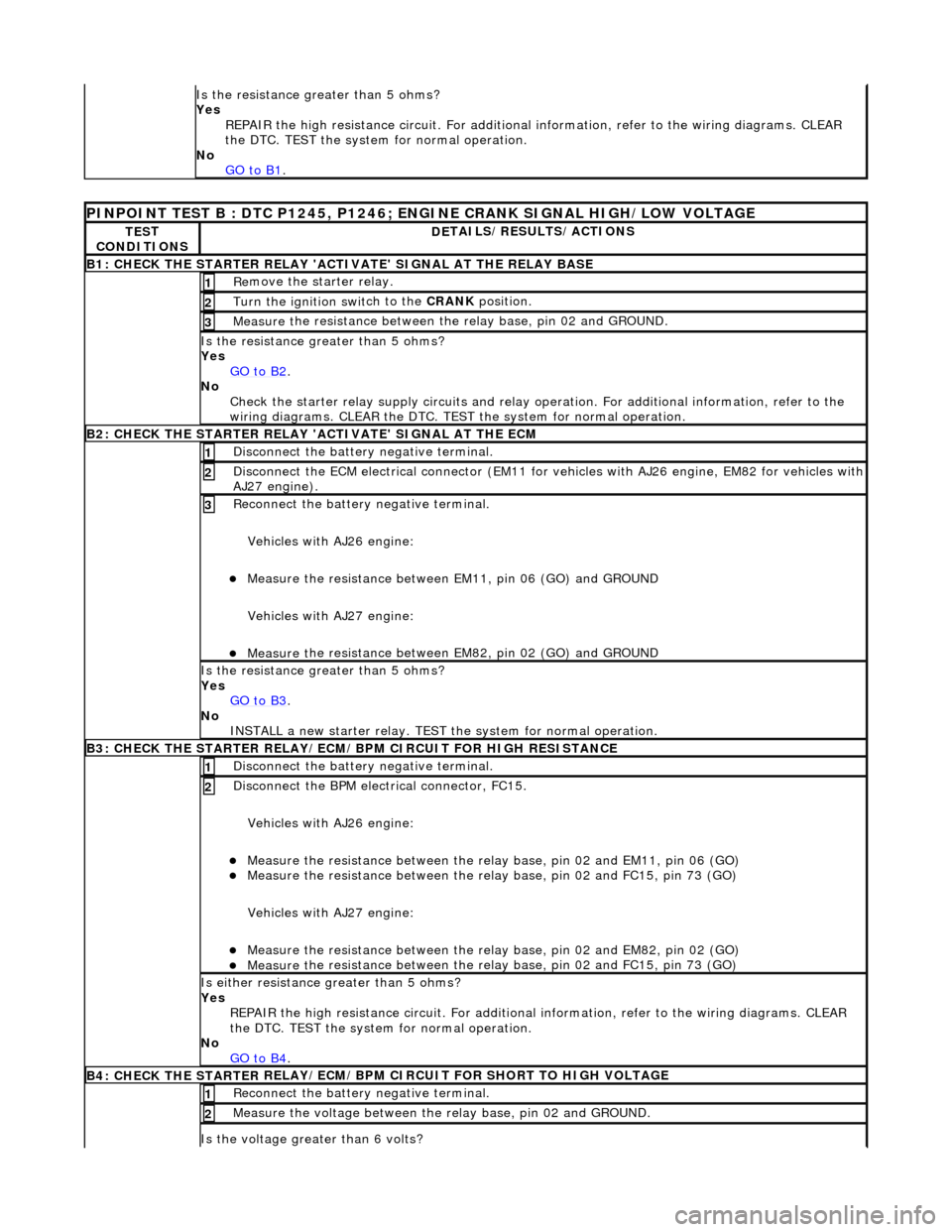
Is the res
istance greater than 5 ohms?
Yes REPAIR the high resistance circui t. For additional information, refer to the wiring diagrams. CLEAR
the DTC. TEST the system for normal operation.
No GO to B1
.
PINPOINT TES
T B : DTC P1245, P1246; ENGINE CRANK SIGNAL HIGH/LOW VOLTAGE
TE
S
T
CONDITIONS
D E
TAILS/RESULTS/ACTIONS
B1: CHECK
THE STARTER
RELAY 'ACTIV
ATE' SIGNAL AT THE RELAY BASE
Re
move the starter relay.
1
Turn the ignition swi
t
ch to the CRANK
position.
2
Measure t
he resistance between th
e relay base, pin 02 and GROUND.
3
Is the res
istance greater than 5 ohms?
Yes GO to B2
.
No Check t
he starter relay supply circui
ts and relay operation. For additi onal information, refer to the
wiring diagrams. CLEAR the DTC. TEST the system for normal operation.
B2: CHECK THE STARTER
RELAY 'A
CTIVATE' SIGNAL AT THE ECM
Disc
onnect the battery negative terminal.
1
D
i
sconnect the ECM electrical connector (EM11 for vehicles with AJ26 engine
, EM82 for vehicles with
AJ27 engine).
2
R e
connect the battery negative terminal.
Vehicles with AJ26 engine:
Meas ure t
he resistance between EM11, pin 06 (GO) and GROUND
Vehicles with AJ27 engine:
Meas ure t
he resistance between EM82, pin 02 (GO) and GROUND
3
Is th
e res
istance greater than 5 ohms?
Yes GO to B3
.
No
IN
STALL a new starter relay. TEST
the system for normal operation.
B3: CHECK THE STARTER
RELAY/ECM/BPM CIRCUIT FOR HIGH RESISTANCE
Di sc
onnect the battery negative terminal.
1
Disc
onne
ct the BPM electrical connector, FC15.
Vehicles with AJ26 engine:
Meas ure t
he resistance between the relay
base, pin 02 and EM11, pin 06 (GO)
Measure t
he resistance between the relay
base, pin 02 and FC15, pin 73 (GO)
Vehicles with AJ27 engine:
Meas ure t
he resistance between the relay
base, pin 02 and EM82, pin 02 (GO)
Measure t
he resistance between the relay
base, pin 02 and FC15, pin 73 (GO)
2
Is either resistance greater
than 5 ohms?
Yes REPAIR the high resistance circui t. For additional information, refer to the wiring diagrams. CLEAR
the DTC. TEST the system for normal operation.
No GO to B4
.
B4: CHECK THE STARTER
RE
LAY/ECM/BPM CIRCUIT FOR SHORT TO HIGH VOLTAGE
Re
connect the battery negative terminal.
1
Meas
ure t
he voltage between the
relay base, pin 02 and GROUND.
2
Is the volt
age greater than 6 volts?
Page 1165 of 2490
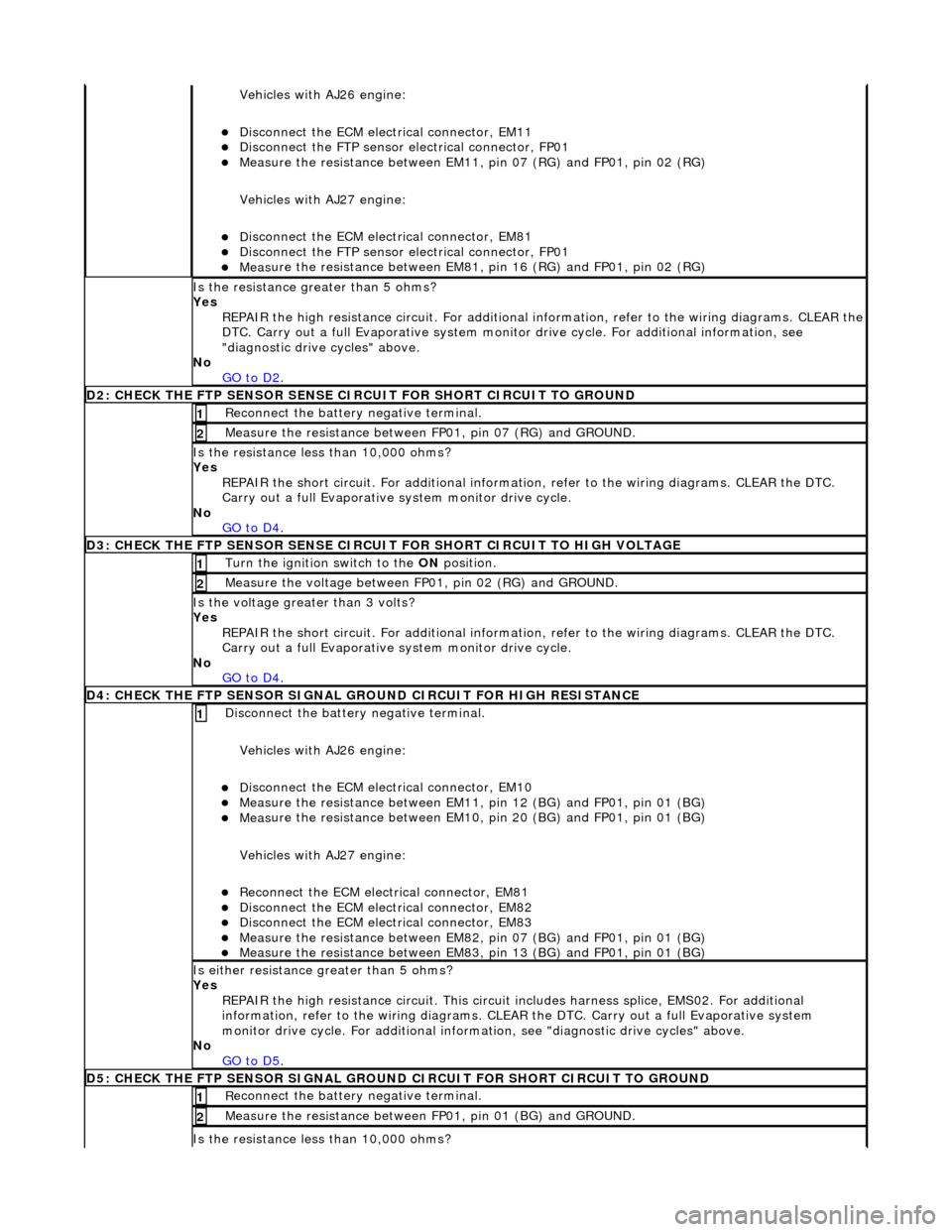
Vehicles with AJ26 en
gine:
D
isconnect the ECM electrical connector, EM11
Di
sconnect the FTP sensor electrical connector, FP01
Meas
ure the resistance between EM11,
pin 07 (RG) and FP01, pin 02 (RG)
Vehicles with AJ27 engine:
D
isconnect the ECM electrical connector, EM81
Di
sconnect the FTP sensor electrical connector, FP01
Meas
ure the resistance between EM81,
pin 16 (RG) and FP01, pin 02 (RG)
Is th
e resistance greater than 5 ohms?
Yes REPAIR the high resistance circuit. For additional information, refer to the wiring diagrams. CLEAR the
DTC. Carry out a full Evaporative system monitor drive cycle. For additional information, see
"diagnostic drive cycles" above.
No GO to D2
.
D2: CHECK
THE FTP SENSOR SENSE CI
RCUIT FOR SHORT CIRCUIT TO GROUND
R
econnect the battery negative terminal.
1
Meas
ure the resistance between
FP01, pin 07 (RG) and GROUND.
2
Is
the resistance less than 10,000 ohms?
Yes REPAIR the short circuit. For addi tional information, refer to the wiring diagrams. CLEAR the DTC.
Carry out a full Evaporative system monitor drive cycle.
No GO to D4
.
D3: CHECK
THE FTP SENSOR SENSE CIRCUI
T FOR SHORT CIRCUIT TO HIGH VOLTAGE
Turn the ignition swi
tch to the ON
position.
1
Measure the
voltage between FP
01, pin 02 (RG) and GROUND.
2
Is th
e voltage greater than 3 volts?
Yes REPAIR the short circuit. For addi tional information, refer to the wiring diagrams. CLEAR the DTC.
Carry out a full Evaporative system monitor drive cycle.
No GO to D4
.
D
4: CHECK THE FTP SENSOR SIGNAL GROUND CIRCUIT FOR HIGH RESISTANCE
Di
sconnect the battery negative terminal.
Vehicles with AJ26 engine:
D
isconnect the ECM electrical connector, EM10
Meas
ure the resistance between EM11, pin 12 (BG) and FP01, pin 01 (BG)
Meas
ure the resistance between EM10, pin 20 (BG) and FP01, pin 01 (BG)
Vehicles with AJ27 engine:
Re
connect the ECM electrical connector, EM81
D
isconnect the ECM electrical connector, EM82
D
isconnect the ECM electrical connector, EM83
Meas
ure the resistance between EM82, pin 07 (BG) and FP01, pin 01 (BG)
Meas
ure the resistance between EM83, pin 13 (BG) and FP01, pin 01 (BG)
1
Is either resi
stance
greater than 5 ohms?
Yes REPAIR the high resistance circui t. This circuit includes harness splice, EMS02. For additional
information, refer to the wiring diagrams. CLEAR the DTC. Carry out a full Evaporative system
monitor drive cycle. For additional informat ion, see "diagnostic drive cycles" above.
No GO to D5
.
D5:
CHECK THE FTP SENSOR SIGNAL GROUND
CIRCUIT FOR SHORT CIRCUIT TO GROUND
R
econnect the battery negative terminal.
1
Meas
ure the resistance between
FP01, pin 01 (BG) and GROUND.
2
Is
the resistance less than 10,000 ohms?
Page 1198 of 2490
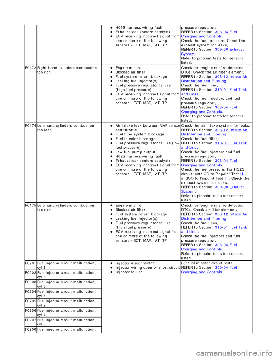
H02S harness wiri
ng fault
E
x
haust leak (before catalyst)
ECM receivi
n
g incorrect signal from
one or more of the following
sensors - ECT, MAF, IAT, TP
pr essure regulator,
REF
ER to Section 303
-04
Fu
el
Charging and Con
t
rols
.
Chec k the
fuel pressure. Check the
exhaust system for leaks,
REFER to Section 309
-00 Ex
haust
Sy
ste
m
.
R e
fer to pinpoint tests for sensors
listed.
P0172Right -
hand cylinders combustion
too rich
Engine m
isfire
Bl
ocked air
filter
F
u
el system return blockage
Leak
i
ng fuel injector(s)
F
u
el pressure regulator failure
(high fuel pressure)
ECM receivi n
g incorrect signal from
one or more of the following
sensors - ECT, MAF, IAT, TP
Chec k for 'en
gine misfire detected'
DTCs. Check the air filter element,
REFER to Section 303
-1 2
Intake Air
Distribu
tion and Filterin
g
.
Chec k the
fuel lines,
REFER to Section 310
-01 Fu
el Tank
and Lines.
Chec k the
fuel injectors and fuel
pressure regulator,
REFER to Section 303
-04 Fu
el
Charging and Con
t
rols
.
R e
fer to pinpoint tests for sensors
listed.
P0174L e
ft-hand cylinders combustion
too lean
Air in
take leak between MAF senso
r and th
ro
ttle
F
u
el filter system blockage
F
u
el injector blockage
F
u
el pressure regulator failure (low
fuel pressure)
Low fu
el pump output
H0
2S harness wiri
ng fault
E
x
haust leak (before catalyst)
ECM receivi
n
g incorrect signal from
one or more of the following
sensors - ECT, MAF, IAT, TP
Check the ai r intak
e system for leaks,
REFER to Section 303
-1 2
Intake Air
Distribu
tion and Filterin
g
.
Check the fuel fi lter,
REF
ER to Section 310
-01
Fu
el Tank
and Lines.
Chec k the
fuel injectors and fuel
pressure regulator,
REFER to Section 303
-04 Fu
el
Charging and Con
t
rols
.
Chec k the
fuel pressure. For HO2S
circuit tests,GO to Pinpoint Test H.
,
a n
dGO to Pinpoint Test
I.
. Check
the
exhaust system for leaks,
REFER to Section 309
-00 Ex
haust
Sy
ste
m
.
R e
fer to pinpoint tests for sensors
listed.
P0175L e
ft-hand cylinders combustion
too rich
Engine m
isfire
Bl
ocked air
filter
F
u
el system return blockage
Leak
i
ng fuel injector(s)
F
u
el pressure regulator failure
(high fuel pressure)
ECM receivi n
g incorrect signal from
one or more of the following
sensors - ECT, MAF, IAT, TP
Chec k for 'en
gine misfire detected'
DTCs. Check air filter element,
REFER to Section 303
-1 2
Intake Air
Distribu
tion and Filterin
g
.
Chec k the
fuel lines,
REFER to Section 310
-01 Fu
el Tank
and Lines.
Chec k the
fuel injectors and fuel
pressure regulator,
REFER to Section 303
-04 Fu
el
Charging and Cont
rols
.
Re
fer to pinpoint tests for sensors
listed.
P0201 Fu
el injector circuit malfunction,
cyl 1
Injector discon n
ected
Inject
or wir
ing open or short circuit
Injector fail
ure
F
o
r fuel injector
circuit tests,
REFER to Section 303
-04 Fu
el
Charging and Con
t
rols
. P0202F
u
el injector circuit malfunction,
cyl 3
P0203F u
el injector circuit malfunction,
cyl 5
P0204F u
el injector circuit malfunction,
cyl 7
P0205F u
el injector circuit malfunction,
cyl 2
P0206F u
el injector circuit malfunction,
cyl 4
P0207F u
el injector circuit malfunction,
cyl 6
P0208F u
el injector circuit malfunction,
Page 1931 of 2490
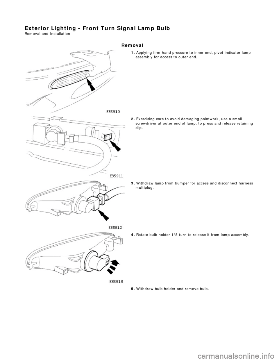
Exterior Lighting - Front Turn Signal Lamp Bulb
Removal and Installation
Removal
1. Applying firm hand pressure to inner end, pivot indicator lamp
assembly for access to outer end.
2. Exercising care to avoid dama ging paintwork, use a small
screwdriver at outer end of lamp, to press and release retaining clip.
3. Withdraw lamp from bumper for access and disconnect harness multiplug.
4. Rotate bulb holder 1/8 turn to release it from lamp assembly.
5. Withdraw bulb holder and remove bulb.
Page 1958 of 2490
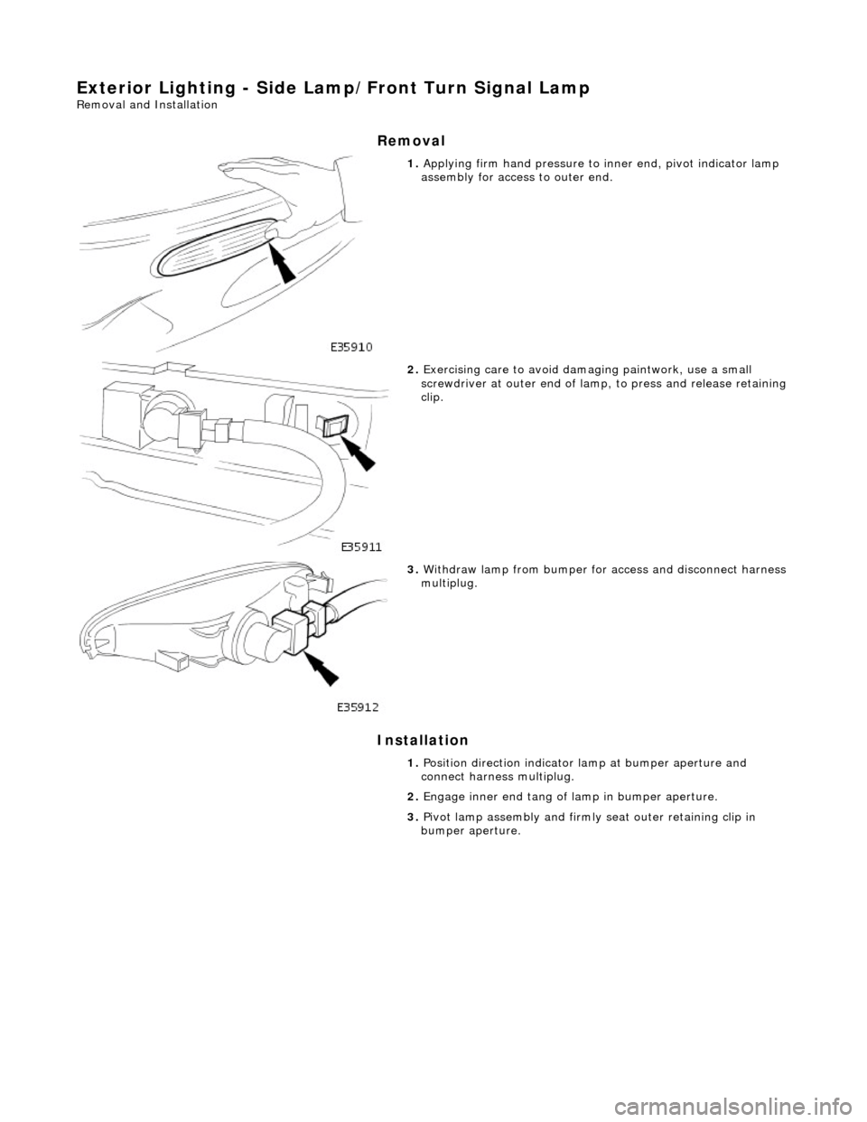
Exterior Lighting - Side Lamp/Front Turn Signal Lamp
Removal and Installation
Removal
Installation
1. Applying firm hand pressure to inner end, pivot indicator lamp
assembly for access to outer end.
2. Exercising care to avoid dama ging paintwork, use a small
screwdriver at outer end of lamp, to press and release retaining clip.
3. Withdraw lamp from bumper for access and disconnect harness multiplug.
1. Position direction indicator la mp at bumper aperture and
connect harness multiplug.
2. Engage inner end tang of lamp in bumper aperture.
3. Pivot lamp assembly and firmly seat outer retaining clip in
bumper aperture.
Page 1959 of 2490
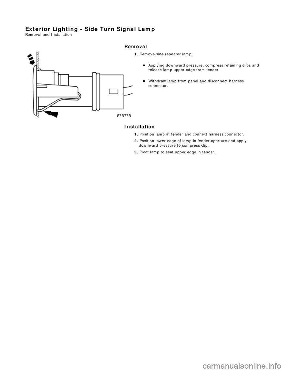
Exterior Lighting - Side Turn Signal Lamp
Removal and Installation
Removal
Installation
1. Remove side repeater lamp.
Applying downward pressure, compress retaining clips and
release lamp upper edge from fender.
Withdraw lamp from panel and disconnect harness
connector.
1. Position lamp at fender and connect harness connector.
2. Position lower edge of lamp in fender aperture and apply
downward pressure to compress clip.
3. Pivot lamp to seat upper edge in fender.