Page 1149 of 2490

The E
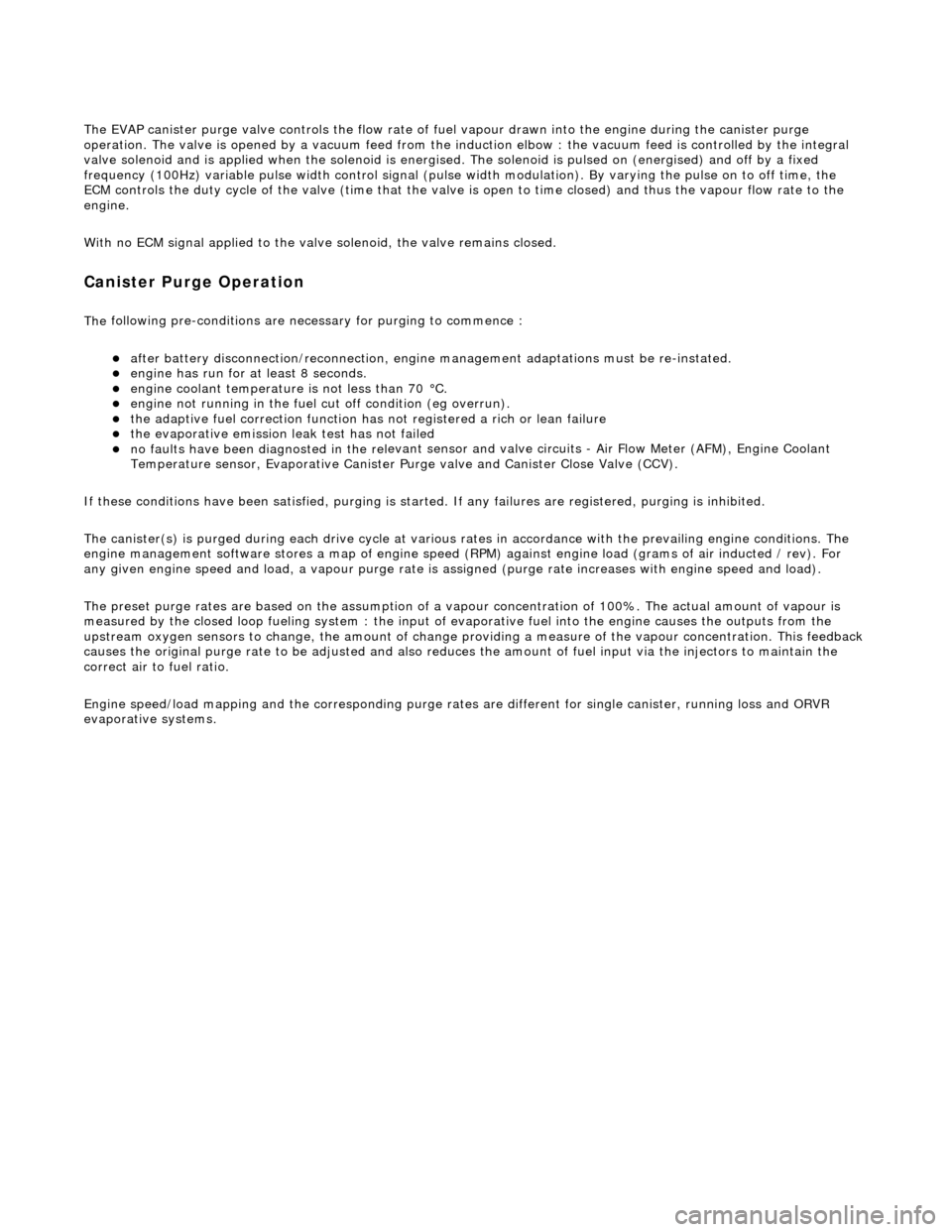
VAP canister purge valve controls th
e flow rate of fuel vapour drawn into the engine during the canister purge
operation. The valve is opened by a vacu um feed from the induction elbow : the vacu um feed is controlled by the integral
valve solenoid and is applied when the so lenoid is energised. The solenoid is pulsed on (energised) and off by a fixed
frequency (100Hz) variable pulse width control signal (pulse width modulation). By varying the pulse on to off time, the
ECM controls the duty cycle of the valve (time that the valve is open to time closed) and thus the vapour flow rate to the
engine.
With no ECM signal applied to the va lve solenoid, the valve remains closed.
Can
ister Purge Operation
The
following pre-conditions are ne
cessary for purging to commence :
aft
er battery disconnection/reconnection, engine
management adaptations must be re-instated.
engine has run for
at least 8 seconds.
engi
ne coolant temperature is not less than 70 °C.
engine
not running in the fuel
cut off condition (eg overrun).
t
he adaptive fuel correction
function has not registered a rich or lean failure
t
he evaporative emission leak test has not failed
no faults have been diagnosted in th
e rel
evant sensor and valve circuits -
Air Flow Meter (AFM), Engine Coolant
Temperature sensor, Evaporativ e Canister Purge valve and Canister Close Valve (CCV).
If these conditions have been satisfied, purging is started. If any failures are registered, purging is inhibited.
The canister(s) is purged during each driv e cycle at various rates in accordance with the prevailing engine conditions. The
engine management software st ores a map of engine speed (RPM) against engine load (grams of air inducted / rev). For
any given engine speed and load, a vapour purge rate is assigned (purge rate increases with engine speed and load).
The preset purge rates are base d on the assumption of a vapour concentratio n of 100%. The actual amount of vapour is
measured by the closed loop fueling system : the input of evaporative fuel into the engine causes the outputs from the
upstream oxygen sensors to change, the am ount of change providing a measure of the vapour concentration. This feedback
causes the original purge rate to be adju sted and also reduces the amount of fuel input via the injectors to maintain the
correct air to fuel ratio.
Engine speed/load mapping and the corresp onding purge rates are different for single canister, running loss and ORVR
evaporative systems.
Page 1241 of 2490

E
lectronic Engine Controls - Engine
Control Module (ECM) Adaptation
Gen
eral Procedures
When to car
ry out adaptations
DTCs P1000/P1111 Conditions for adaptation
Fuelling Adaptations Drive Cycle
•
NOTE: Make sure the engine is at normal operating
temperature. (75°C, 167°F) 1.
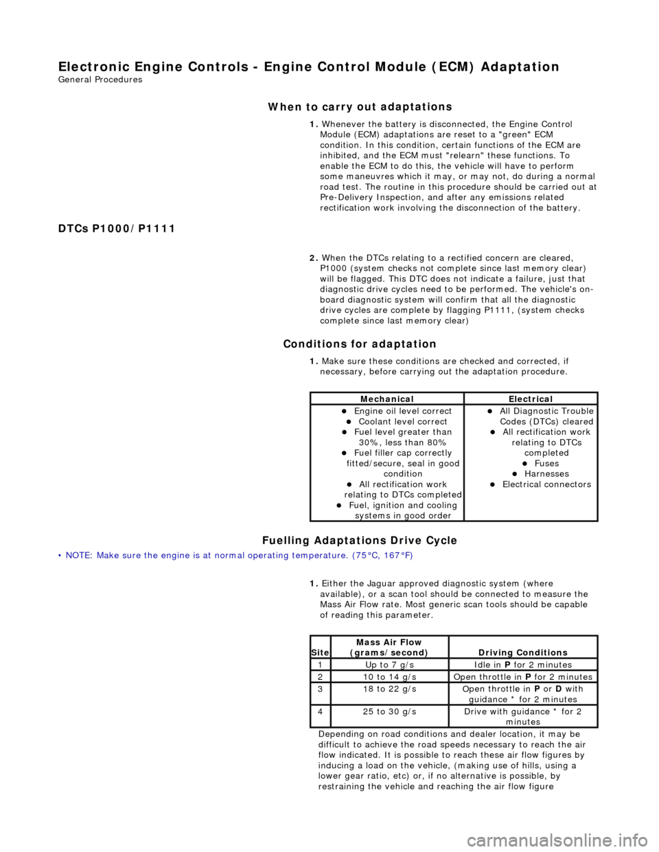
Whenever the battery is disconnected, the Engine Control
Module (ECM) adaptations are reset to a "green" ECM
condition. In this condition, certain functions of the ECM are
inhibited, and the ECM must "r elearn" these functions. To
enable the ECM to do this, the vehicle will have to perform
some maneuvres which it may, or may not, do during a normal
road test. The routine in this pr ocedure should be carried out at
Pre-Delivery Inspection, and after any emissions related
rectification work involving the disconnection of the battery.
2. When the DTCs relating to a rectified concern are cleared,
P1000 (system checks not complete since last memory clear)
will be flagged. This DTC does no t indicate a failure, just that
diagnostic drive cycles need to be performed. The vehicle's on-
board diagnostic system will confirm that all the diagnostic
drive cycles are complete by flagging P1111, (system checks
complete since last memory clear)
1. Make sure these conditions are checked and corrected, if
necessary, before carrying ou t the adaptation procedure.
MechanicalElectrical
Engi
ne oil level correct
Coo
lant level correct
F
uel level greater than
30%, less than 80%
F
uel filler cap correctly
fitted/secure, seal in good condition
Al
l rectification work
relating to DTCs completed
F
uel, ignition and cooling
systems in good order
Al
l Diagnostic Trouble
Codes (DTCs) cleared
Al
l rectification work
relating to DTCs completed
F
uses
Harnes
ses
E
lectrical connectors
1.
Either
the Jaguar approved diagnostic system (where
available), or a scan tool should be connected to measure the
Mass Air Flow rate. Most generi c scan tools should be capable
of reading this parameter.
Depending on road conditions and dealer location, it may be
difficult to achieve the road sp eeds necessary to reach the air
flow indicated. It is possible to reach these air flow figures by
inducing a load on the vehicle, (making use of hills, using a
lower gear ratio, etc) or, if no alternative is possible, by
restraining the vehicle and re aching the air flow figure
Si
te
Mass Air Flow
(gra
ms/second)
D
riving Conditions
1Up t
o 7 g/s
Idle
in
P for 2 minutes
21
0 to 14 g/s
O
pen throttle in
P for 2 minutes
31
8 to 22 g/s
O
pen throttle in
P or D with
guidance * for 2 minutes
42
5 to 30 g/s
D
rive with guidance * for 2
minutes
Page 1341 of 2490
3. NOTE: Ensure extreme clea nliness and never reuse
transmission fluid.
Using a new gasket, install the fl uid pan and tighten the fixings
to the specified torque figure.
4. Connect the battery and fit the battery cover..
Reset the radio and the clock.
5. Refer to (44.24.02) for fluid fill procedure.
Page 1351 of 2490
Fit the inpu
t speed sensor and
tighten the retaining screw to
the specified to rque figure..
5. Re
position the inte
rnal harness for.
R
elease the internal harness
from the retaining clips.
6. Connect
the five pressure re
gulator connectors and three
solenoid connectors.
7. N
OTE: Ensure extreme clea
nliness and never reuse
transmission fluid.
Using a new gasket, install the fl uid pan and tighten the twenty-
two fixings to the specified. torque figure
8. Connect the battery and fit the battery cover..
Reset th
e radio and the clock.
9. Refer to (44.24.02) for fluid fill procedure.
10. Check for leaks and remove spilt fluid.
Page 1353 of 2490
Installation
1.
NOTE: M6 fixing.
Connect the multiplug, install the output speed sensor and
securing bracket. Tighten the screw to the specified torque
figure.
2. NOTE: Ensure extreme clea nliness and never reuse
transmission fluid.
Using a new gasket, install the fl uid pan and tighten the twenty-
two fixings to the specified. torque figure.
3. Connect the battery and fit the battery cover..
Reset the radio and the clock.
4. Refer to (44.24.02) for fluid fill procedure.
Page 1356 of 2490
3. NOTE: Ensure extreme clea nliness and never reuse
transmission fluid.
Using a new gasket, install the fl uid pan and tighten the twenty-
two fixings to the specified torque figure.
4. Connect the battery and fit the battery cover..
Reset the radio and the clock.
5. Refer to (44.24.02) for fluid fill procedure.
Page 1358 of 2490
Installation
1.
NOTE: A replacement TCM may only be obtained from an
authorized Jaguar dealer and MU ST be ordered against the VIN.
Fitting a new TCM is the revers e of the removal procedure.
At this point ensure that the ECM is correctly located and
pushed fully rearward against the housing.
2. Connect the battery and fit the battery cover..
Reset the radio and the clock.
Page 1366 of 2490
Using a new gasket, install the fluid pan and tighten the twenty-
two bolts to the specified torque figure.
8. Connect the battery and fit the battery cover..
Reset the radio and the clock.
9. Refer to (44.24.02) for fluid fill procedure.