Page 1864 of 2490

Information and Message Center - Information and Message Center
Description and Operation
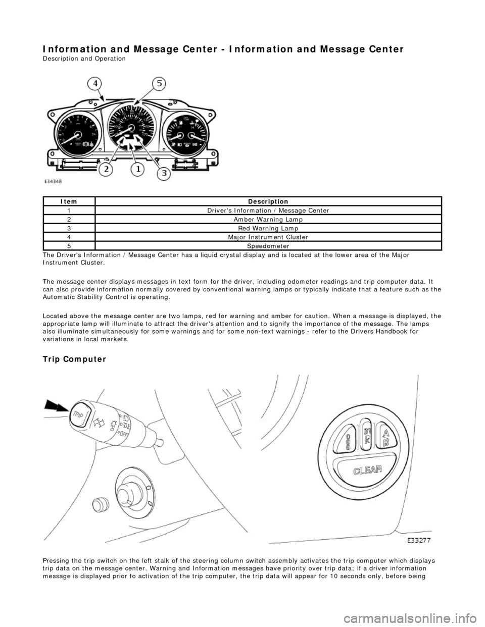
The Driver's Information / Message Center has a liquid crystal display and is located at the lower area of the Major
Instrument Cluster.
The message center displays messages in text form for the driver, including odometer readings an d trip computer data. It
can also provide information normally covered by conventional wa rning lamps or typically indicate that a feature such as the
Automatic Stability Control is operating.
Located above the message center are two lamps, red for warning and amber for caution. When a message is displayed, the
appropriate lamp will illuminate to attract the driver's attention and to signify the importance of the message. The lamps
also illuminate simultaneously for some warnings and for some non-text warnin gs - refer to the Drivers Handbook for
variations in local markets.
Trip Computer
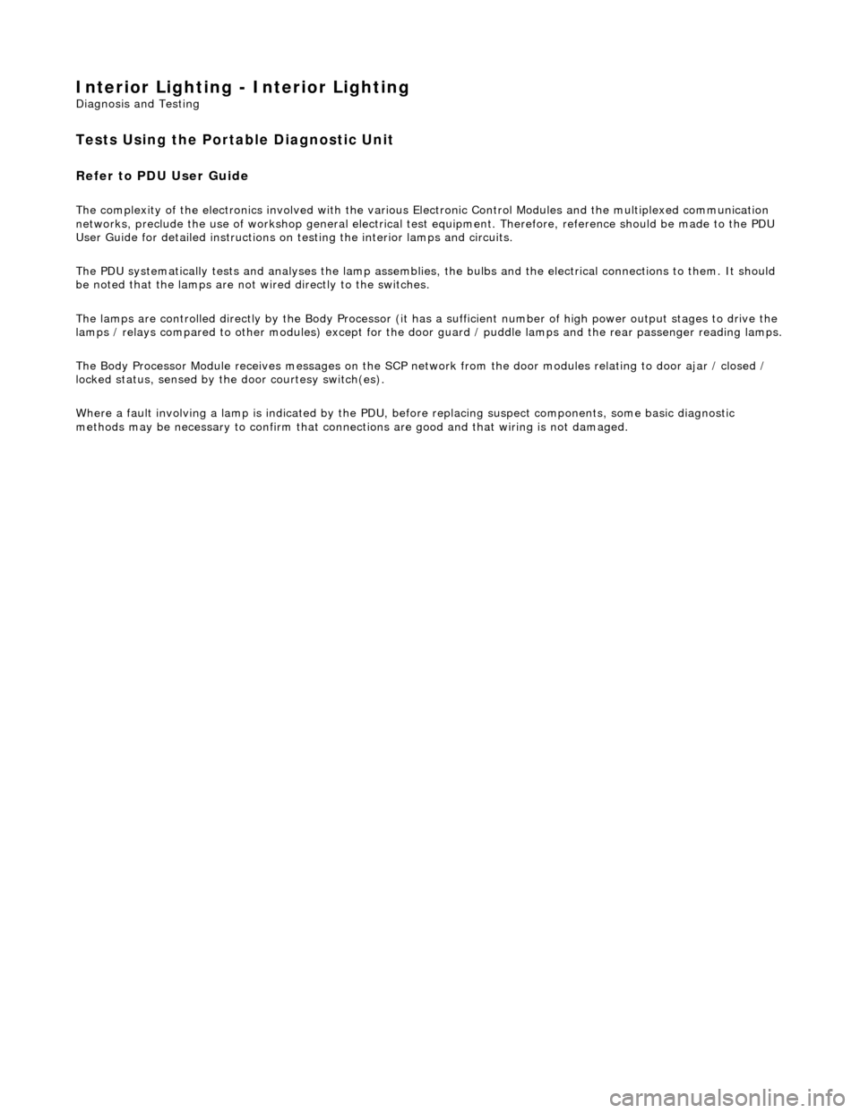
Pressing the trip switch on the left stalk of the steering colu mn switch assembly activates the trip computer which displays
trip data on the message center. Warning and Information messages have priority ov er trip data; if a driver information
message is displayed prior to activation of the trip computer , the trip data will appear for 10 seconds only, before being
ItemDescription
1Driver's Information / Message Center
2Amber Warning Lamp
3Red Warning Lamp
4Major Instrument Cluster
5Speedometer
Page 1865 of 2490
replaced by the original message.
Each successive press of the trip switch causes the computer to continually cycle through the stored data which is then
displayed on the message center.
The trip computer switch pack, mounted on the fascia is only enabled while the trip computer output is displayed. Refer to
the Drivers Handbook for fu ll operating instructions.
Page 1866 of 2490
Information and Message Center - Information and Message Center
Diagnosis and Testing
Tests Using the Portable Diagnostic Unit
Refer to PDU User Guide
The complexity of the electronics involved with the speedomete r and instrument cluster, of which the Message Center is a
part, and the two multiplexed communication networks which ar e connected to it preclude the use of workshop general
electrical test equipment. Therefore, refe rence should be made to the PDU User Guide for detailed instructions on testing
the speedometer and odometer.
The PDU systematically te sts and analyses all functions and the various systems affected by it.
Where a fault is indicated, before replac ing a component, some basic diagnostic methods may be necessary to confirm that
connections are good and that wiring is not damaged.
Page 1867 of 2490
Information and Message Center - Message Center Switch
Removal and Installation
Removal
Installation
1.
Disconnect battery ground cable; refer to 86.15.19.
2. Remove instrument panel veneer panel; refer to 76.47.24.
3. Remove trip computer switch pack.
Use suitable small screwdriver to displace upper retaining
tang.
Reposition switch pack for access to connector.
Disconnect connector and remove switch pack.
1. Installation is reverse of removal.
Page 1904 of 2490
Audio Unit - Audio System
Description and Operation
The choice of two entertainment system s is available; base or premium.
The base system comprises a radio cassette player with in tegral message display and "Phone Ready" controls for an
accessory telephone; door speakers and tweeters.
The premium system has the following additional components: power amplifier, CD autochanger, sub-woofer and 'A' post
tweeters fitted instead of front door tweeters.
Both systems can be operated remotely by use of switches loca ted on the steering wheel and have an electrically operated
aerial.
Telephone controls incorporated in the ra dio cassette unit facilitate inclusion of the GSM hands free telephone system
available as optional equipment.
After diagnostic or repair operations, refer to the Sound System Handbook for setting-up procedures and operation.
Page 1905 of 2490
The CD Autochanger and amplifier are mounte d on a bracket as a single assembly located at the left hand side of the trunk.
The complete assembly must be removed before the CD Autochanger and amplifier can be separated.
When the CD option is selected, the CD unit cycles through a self-check sequence and indicates the current status on the
message display. Refer to the Sound System Ha ndbook for complete operating instructions.
Page 1964 of 2490

Interior Lighting - Interior Lighting
Diagnosis and Testing
Tests Using the Portable Diagnostic Unit
Refer to PDU User Guide
The complexity of the electronics involved with the various Electronic Control Modules and the multiplexed communication
networks, preclude the use of workshop general electrical test equipment. Therefore, reference should be made to the PDU
User Guide for detailed inst ructions on testing the interior lamps and circuits.
The PDU systematically tests and analyses the lamp assemblies, the bulbs and the electrical connections to them. It should
be noted that the lamps are not wired directly to the switches.
The lamps are controlled directly by the Bo dy Processor (it has a sufficient number of high power output stages to drive the
lamps / relays compared to other module s) except for the door guard / puddle lamps and the rear passenger reading lamps.
The Body Processor Module receives messages on the SCP network from the door modules relating to door ajar / closed /
locked status, sensed by the door courtesy switch(es).
Where a fault involving a lamp is indicated by the PDU, be fore replacing suspect components, some basic diagnostic
methods may be necessary to confirm that connecti ons are good and that wiring is not damaged.
Page 2307 of 2490

cooling duct.
The windshield washer is operated by pressing the button at the end of the wiper control stalk switch. Pressing and
releasing the button operates the washer for 1 to 1.4 seconds and the wiper completes three sweeps. An optional drip wipe
function adds a further sweep of the wiper after a 4 second delay, to clear residual fluid from the windshield. If the button is
held depressed, the washer and wiper will operate continuous ly for up to 20 seconds. When the button is released, the
wiper will again complete three further sweeps.
Headlamp Powerwash
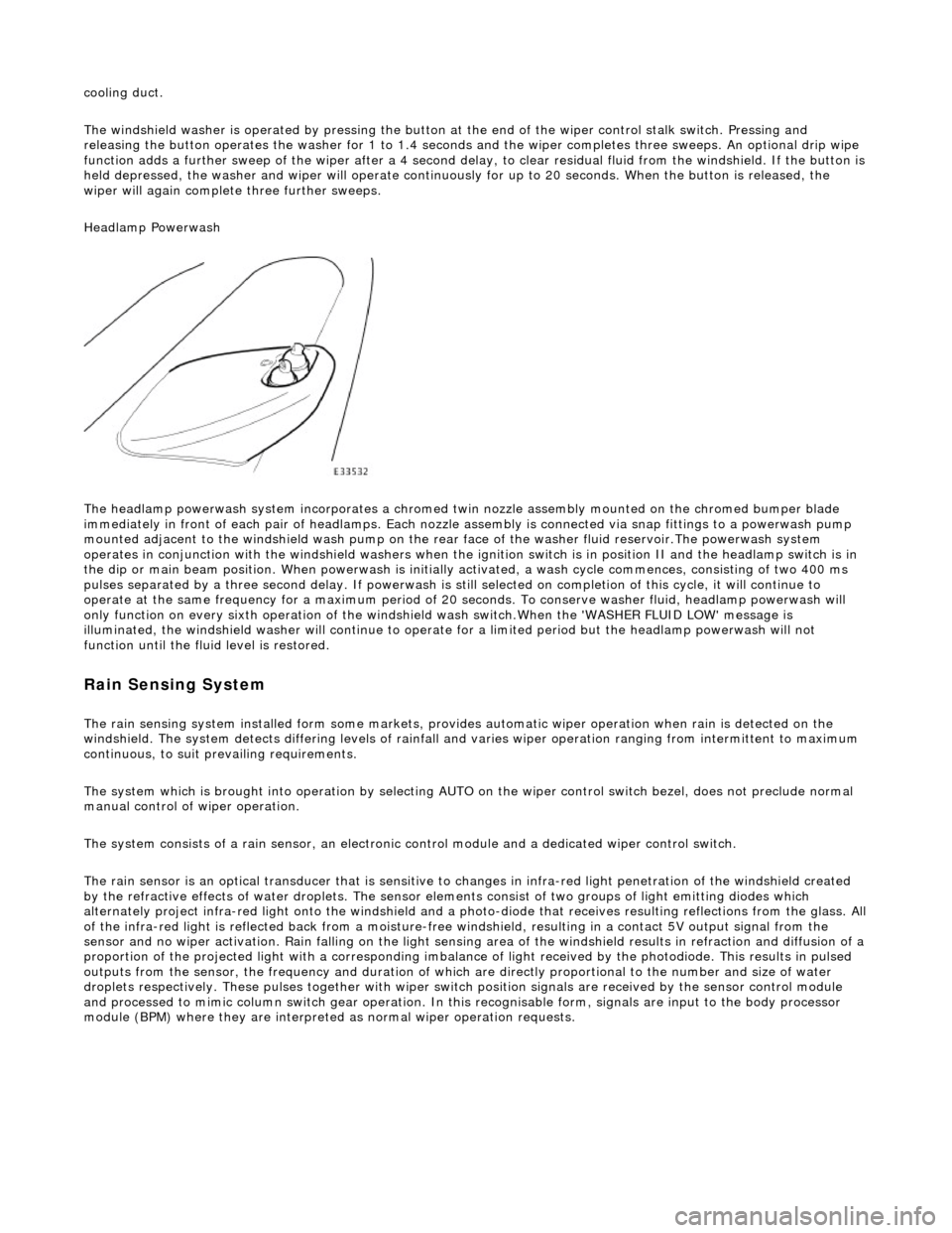
The headlamp powerwash system incorporates a chromed twin nozzle assembly mounted on the chromed bumper blade
immediately in front of each pair of he adlamps. Each nozzle assembly is connected via snap fittings to a powerwash pump
mounted adjacent to the windshield wash pump on the rear face of the washer fluid reservoir.The powerwash system
operates in conjunction with the windshield washers when the ignition switch is in position II and the headlamp switch is in
the dip or main beam position. When powerwash is initially activated, a wash cycle commences, consisting of two 400 ms
pulses separated by a three second delay. If powerwash is still selected on completion of this cycle, it will continue to
operate at the same frequency for a maximum period of 20 se conds. To conserve washer fluid, headlamp powerwash will
only function on every sixth operation of the windshie ld wash switch.When the 'WASHER FLUID LOW' message is
illuminated, the windshield washer will continue to operat e for a limited period but the headlamp powerwash will not
function until the fluid level is restored.
Rain Sensing System
The rain sensing system installed form so me markets, provides automatic wiper operation when rain is detected on the
windshield. The system detects differing le vels of rainfall and varies wiper operation ranging from intermittent to maximum
continuous, to suit prevailing requirements.
The system which is brought into operation by selecting AUTO on the wiper control switch bezel, does not preclude normal
manual control of wiper operation.
The system consists of a rain sensor, an electronic control module and a dedicated wiper control switch.
The rain sensor is an optical transducer that is sensitive to changes in infra-red light penetration of the windshield created
by the refractive effects of water drople ts. The sensor elements consist of two groups of light emitting diodes which
alternately project infra-red light onto th e windshield and a photo-diode that receiv es resulting reflections from the glass. A ll
of the infra-red light is reflected back from a moisture-free windshield, resulting in a contact 5V output signal from the
sensor and no wiper activation. Rain falling on the light sensing area of the wi ndshield results in refraction and diffusion of a
proportion of the projected light with a corresponding imbalance of light received by the photodiode. This results in pulsed
outputs from the sensor, the frequency and duration of which are directly proportional to the number and size of water
droplets respectively. These pulses together with wiper switch position signals are received by the sensor control module
and processed to mimic column switch gear operation. In this recognisable form, signals are input to the body processor
module (BPM) where they are interprete d as normal wiper operation requests.