Page 2311 of 2490
Wipers and Washers - Headlamp Washer Pump
Removal and Installation
Removal
Installation
1.
Remove battery cover and disc onnect ground cable from
battery terminal. Refer to 86.15.19.
2. Raise front of vehicle and support on stands.
3. Remove RH front wheel.
4. Remove RH wheelarch liner. Refer to Section 501-02.
5. Position a suitable drain recept acle under washer reservoir.
6. Supporting reservoir, ca refully withdraw pump.
7. Allow fluid to drain from reservoir.
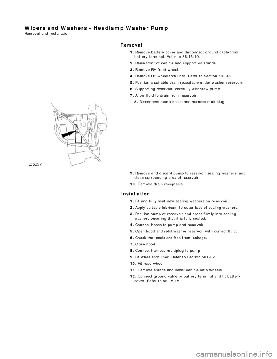
8. Disconnect pump hoses and harness multiplug.
9. Remove and discard pump to re servoir sealing washers. and
clean surrounding area of reservoir.
10. Remove drain receptacle.
1. Fit and fully seat new sealing washers on reservoir.
2. Apply suitable lubricant to outer face of sealing washers.
3. Position pump at reservoir and press firmly into sealing
washers ensuring that it is fully seated.
4. Connect hoses to pump and reservoir.
5. Open hood and refill washer re servoir with correct fluid.
6. Check that seals are free from leakage.
7. Close hood.
8. Connect harness multiplug to pump.
9. Fit wheelarch liner. Refe r to Section 501-02.
10. Fit road wheel.
11. Remove stands and lowe r vehicle onto wheels.
12. Connect ground cable to batt ery terminal and fit battery
cover. Refer to 86.15.15.
Page 2314 of 2490
Wipers and Washers - Windshield Washer Pump
Removal and Installation
Removal
Installation
1.
Remove battery cover and disc onnect ground cable from
battery terminal. Refer to 86.15.19.
2. Raise front of vehicle and support on stands.
3. Remove RH front wheel.
4. Remove RH wheelarch liner. Refer to Section 501-02.
5. Position a suitable drain recept acle under washer reservoir.
6. Supporting reservoir, ca refully withdraw pump.
7. Allow fluid to drain from reservoir.
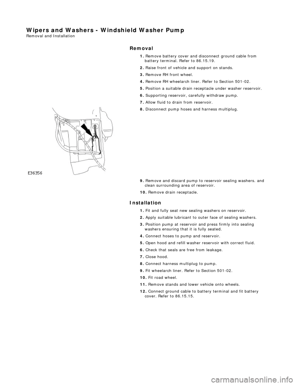
8. Disconnect pump hoses and harness multiplug.
9. Remove and discard pump to re servoir sealing washers. and
clean surrounding area of reservoir.
10. Remove drain receptacle.
1. Fit and fully seat new sealing washers on reservoir.
2. Apply suitable lubricant to outer face of sealing washers.
3. Position pump at reservoir and press firmly into sealing
washers ensuring that it is fully seated.
4. Connect hoses to pump and reservoir.
5. Open hood and refill washer re servoir with correct fluid.
6. Check that seals are free from leakage.
7. Close hood.
8. Connect harness multiplug to pump.
9. Fit wheelarch liner. Refe r to Section 501-02.
10. Fit road wheel.
11. Remove stands and lowe r vehicle onto wheels.
12. Connect ground cable to batt ery terminal and fit battery
cover. Refer to 86.15.15.
Page 2315 of 2490
Wipers and Washers - Windshield Washer Reservoir
Removal and Installation
Removal
Installation
1.
Open hood and fit fender cover.
2. Raise front of vehicle and support on stands.
3. Remove RH front wheel.
4. Remove RH front wheel arch li ner. Refer to Section 501-02.
5. Remove front undertray. Refer to Section 501-02.
6. Remove windshield washer and headlamp powerwash pumps
from reservoir. Refer to op erations in this section.
7. Disconnect Low Level indicator mu ltiplug. Refer to operations
in this section.
8. Carefully remove filler cap from reservoir filler neck.
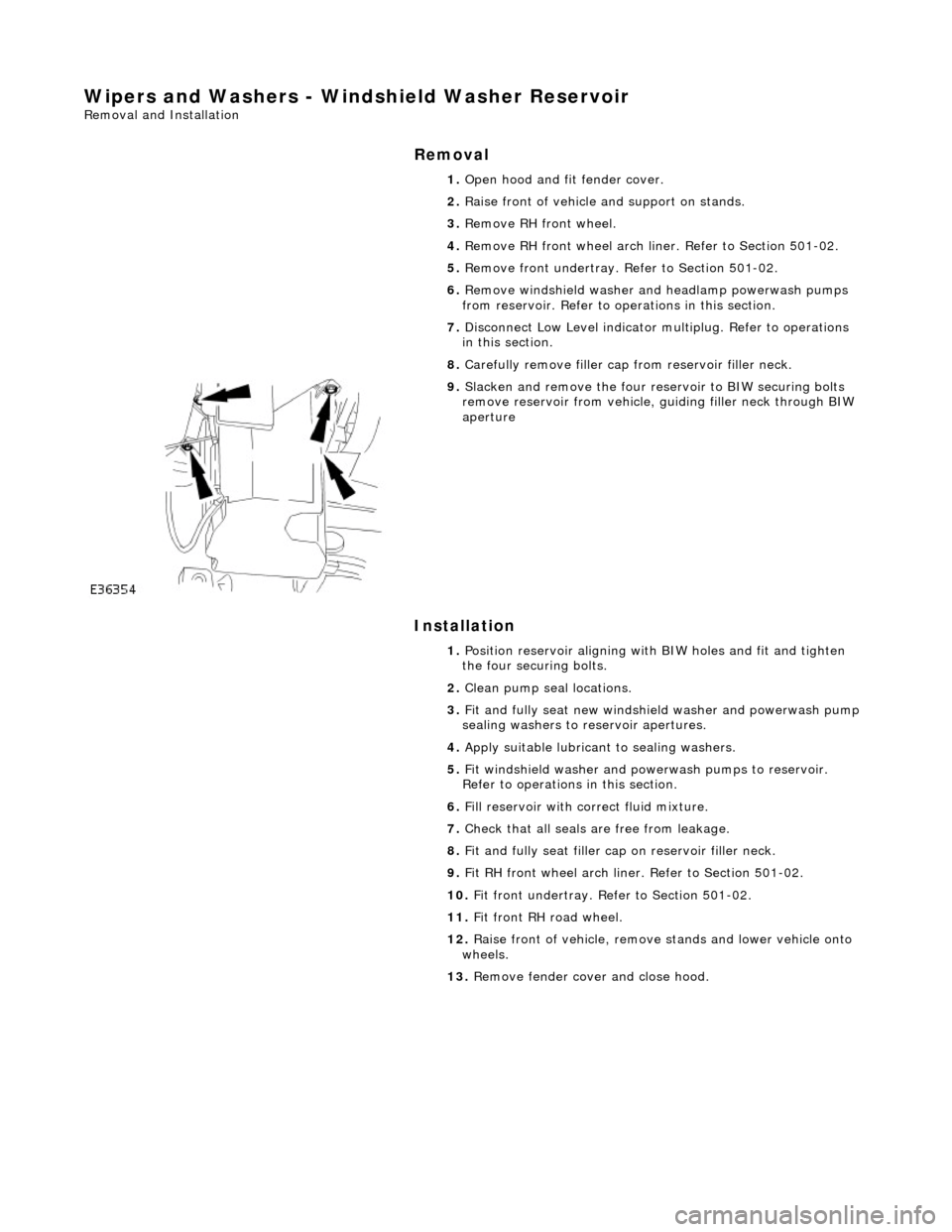
9. Slacken and remove the four re servoir to BIW securing bolts
remove reservoir from vehicle, guiding filler neck through BIW
aperture
1. Position reservoir aligning with BIW holes and fit and tighten
the four securing bolts.
2. Clean pump seal locations.
3. Fit and fully seat new windshie ld washer and powerwash pump
sealing washers to reservoir apertures.
4. Apply suitable lubricant to sealing washers.
5. Fit windshield washer and powerwash pumps to reservoir.
Refer to operations in this section.
6. Fill reservoir with correct fluid mixture.
7. Check that all seals are free from leakage.
8. Fit and fully seat filler cap on reservoir filler neck.
9. Fit RH front wheel arch liner. Refer to Section 501-02.
10. Fit front undertray. Refer to Section 501-02.
11. Fit front RH road wheel.
12. Raise front of vehicle, remove stands and lower vehicle onto
wheels.
13. Remove fender cover and close hood.
Page 2421 of 2490
Uni-Body, Subframe and Mounting System - Front Axle Crossmember
Removal and Installation
Removal
CAUTION: Replacement of nuts and bolts: Various thread-locking devices are used on nuts and bolts throughout the
vehicle. These devices restrict the number of times a nut or bolt can be used. See section 100-00 for information.
Special Tool(s)
Tie-Rod-End Taper Separator
211-098 (JD 100)
Engine Support Beam
303-021 (MS 53D)
1. Position vehicle on a four-post lift.
2. Raise front of vehicle and support on stands.
3. Remove battery cover and disc onnect ground cable from
battery terminal. Refer to section 86.15.15.
4. Open hood to service position, and fit covers to fenders.
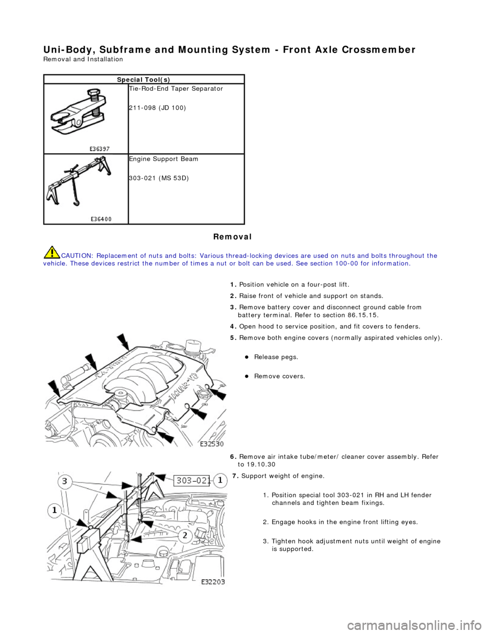
5. Remove both engine covers (nor mally aspirated vehicles only).
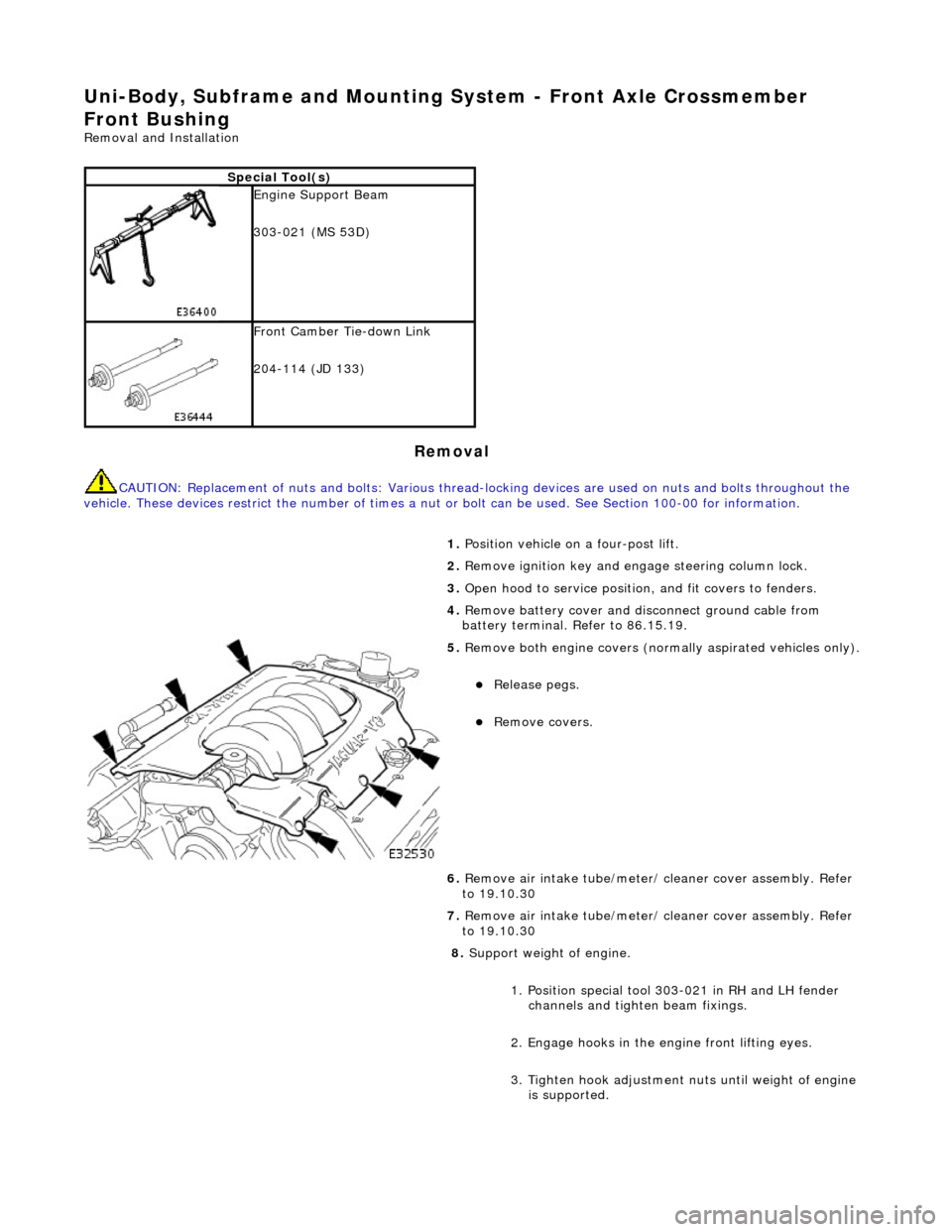
Release pegs.
Remove covers.
6. Remove air intake tube/meter/ cleaner cover assembly. Refer
to 19.10.30
7. Support weight of engine.
1. Position special tool 303-021 in RH and LH fender channels and tighte n beam fixings.
2. Engage hooks in the en gine front lifting eyes.
3. Tighten hook adjustment nuts until weight of engine is supported.
Page 2439 of 2490
Uni-Body, Subframe and Mounting System - Front Axle Crossmember
Front Bushing
Removal and Installation
Removal
CAUTION: Replacement of nuts and bolts: Various thread-locking devices are used on nuts and bolts throughout the
vehicle. These devices restrict the number of times a nut or bolt can be used. See Section 100-00 for information.
Special Tool(s)
Engine Support Beam
303-021 (MS 53D)
Front Camber Tie-down Link
204-114 (JD 133)
1. Position vehicle on a four-post lift.
2. Remove ignition key and en gage steering column lock.
3. Open hood to service position, and fit covers to fenders.
4. Remove battery cover and disc onnect ground cable from
battery terminal. Refer to 86.15.19.
5. Remove both engine covers (nor mally aspirated vehicles only).
Release pegs.
Remove covers.
6. Remove air intake tube/meter/ cleaner cover assembly. Refer
to 19.10.30
7. Remove air intake tube/meter/ cleaner cover assembly. Refer
to 19.10.30
8. Support weight of engine.
1. Position special tool 303-021 in RH and LH fender channels and tighte n beam fixings.
2. Engage hooks in the en gine front lifting eyes.
3. Tighten hook adjustment nuts until weight of engine is supported.
Page 2450 of 2490
Uni-Body, Subframe and Mounting System - Front Axle Crossmember
Front Bushing Heat Shield
Removal and Installation
Removal
CAUTION: Replacement of nuts and bolts: Various thread-locking devices are used on nuts and bolts throughout the
vehicle. These devices restrict the number of times a nut or bolt can be used. See Section 100-00 for information.
Special Tool(s)
Engine Support Beam
303-021 (MS 53D)
Front Camber Tie-down Link
204-114 (JD 133)
1. Position vehicle on a four-post lift.
2. Remove ignition key and en gage steering column lock.
3. Open hood to service position, and fit covers to fenders.
4. Remove battery cover and disc onnect ground cable from
battery terminal. Refer to section 86.15.15.
5. Remove both engine covers (nor mally aspirated vehicles only).
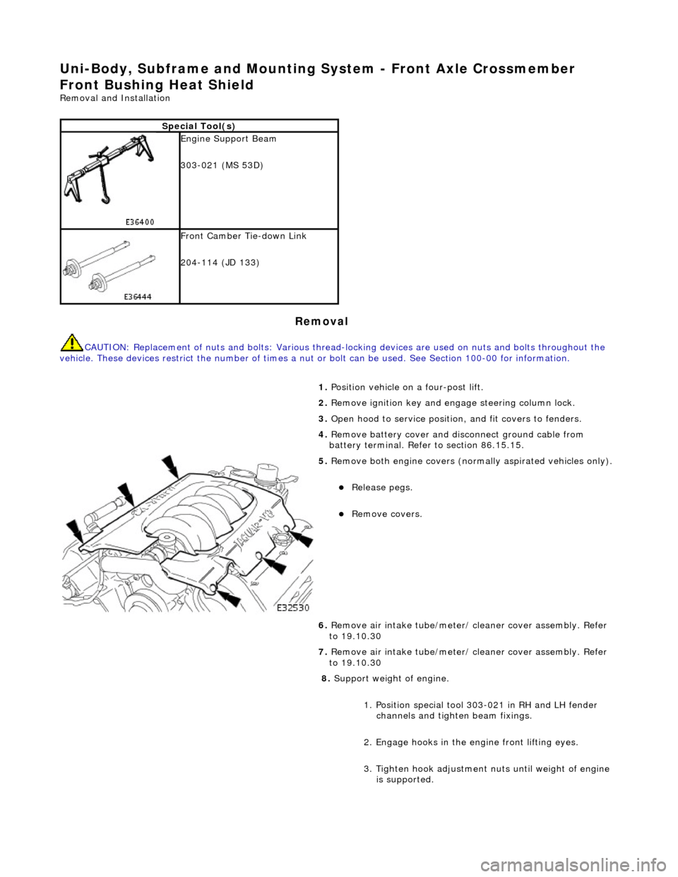
Release pegs.
Remove covers.
6. Remove air intake tube/meter/ cleaner cover assembly. Refer
to 19.10.30
7. Remove air intake tube/meter/ cleaner cover assembly. Refer
to 19.10.30
8. Support weight of engine.
1. Position special tool 303-021 in RH and LH fender channels and tighte n beam fixings.
2. Engage hooks in the en gine front lifting eyes.
3. Tighten hook adjustment nuts until weight of engine is supported.
Page 2461 of 2490
Uni-Body, Subframe and Mounting System - Front Axle Crossmember Rear
Bushing
Removal and Installation
Removal
CAUTION: Replacement of nuts and bolts: Various thread-locking devices are used on nuts and bolts throughout the
vehicle. These devices restrict the number of times a nut or bolt can be used. See section 100-00 for information.
Special Tool(s)
Tie-Rod-End Taper Separator
211-098 (JD 100)
Engine Support Beam
303-021 (MS 53D)
1. Position vehicle on a four-post lift.
2. Raise front of vehicle and support on stands.
3. Remove battery cover and disc onnect ground cable from
battery terminal. Refer to section 86.15.15.
4. Open hood to service position, and fit covers to fenders.
5. Remove both engine covers (nor mally aspirated vehicles only).
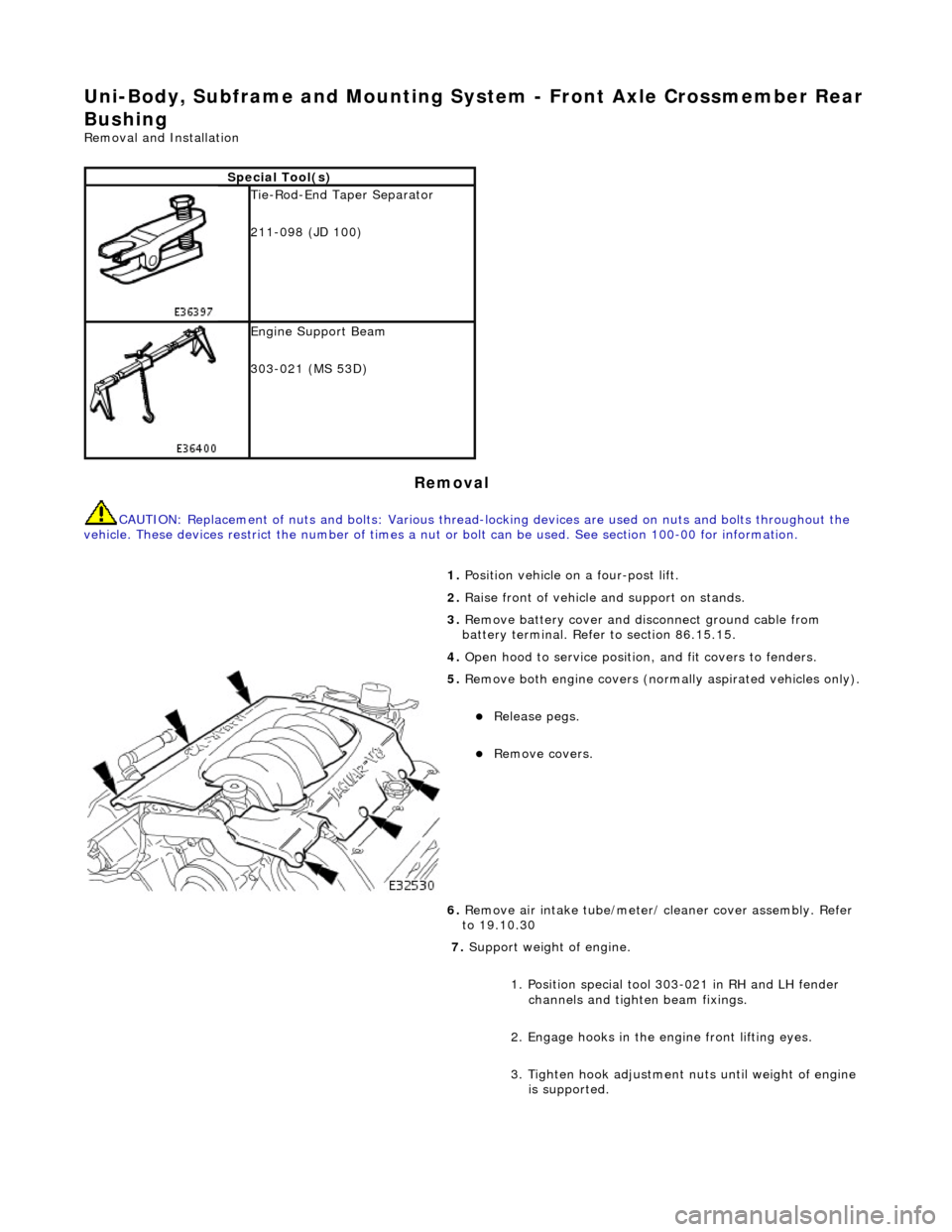
Release pegs.
Remove covers.
6. Remove air intake tube/meter/ cleaner cover assembly. Refer
to 19.10.30
7. Support weight of engine.
1. Position special tool 303-021 in RH and LH fender channels and tighte n beam fixings.
2. Engage hooks in the en gine front lifting eyes.
3. Tighten hook adjustment nuts until weight of engine is supported.
Page:
< prev 1-8 9-16 17-24