Page 1032 of 2490
Fuel Char
ging and Controls - Fu
el Injection Supply Manifold LH
Remo
val and Installation
Remov
a
l
Installation
1. Re
move fuel injectors; refer to (SC) 18.10.01.
2. Disc
onnect fuel feed
pipe from fuel rail.
1. Remove two bolts.
2. Reposition fuel feed pipe.
3. Discard O-ring.
3. Re
move fuel rail from charge air cooler adaptor.
1. Remove three bolts.
2. Reposition fuel rail and remove cross-over pipe securing bolt.
Di
scard O-ring from fuel cross-over pipe.
R
e
move fuel rail.
4. Re
move seals between fuel rail
and charge air cooler adaptor.
1. Discard seals.
2. Clean and inspect mating faces.
1. Install new seals between fuel rail and charge air cooler
adapter ensuring that they are fully seated.
2. Install fuel rail to fuel cross-over pipe.
Inst al
l new O-ring and lubricate with petroleum jelly.
1. Install bolt.
Page 1034 of 2490
Fuel Char
ging and Controls - Fu
el Injection Supply Manifold RH
Remo
val and Installation
Remov
a
l
1.
Re
move fuel injectors; refer to (SC) 18.10.01.
2. Disc
onnect fuel pressure regulator.
1. Remove bolts.
2. Reposition pres sure regulator.
Disc
ard O-ring.
3. Re
move fuel rail from charge air cooler adaptor.
1. Remove three bolts.
2. Remove fuel rail; still co nnected to fuel crossover pipe
and fuel return pipe.
4. Re
move fuel rail from fuel cross-over pipe.
1. Remove bolt.
2. Discard O-ring.
5. Re
move fuel rail to charge air cooler adaptor seals.
1. Discard seals.
2. Clean and inspect mating faces.
Page 1036 of 2490
Fuel Char
ging and Controls - Fuel
Injection Supply Manifold Pipe
Remo
val and Installation
Remov
a
l
WARNING: B
E
FORE PROCEEDING, IT IS ESSENTIAL THAT
THE WARNING NOTES GIVEN IN SECTION 100-00 (UNDER
THE HEADING 'SAFETY PRECAUTION S') ARE READ AND UNDERSTOOD.
In
stallation
1.
De
pressurize fuel syst
em; refer to 19.50.02.
2. Disconnect battery ground cable (IMPORTANT, see SRO
86.15.19 for further information).
3. Re
move inlet manifold
fuel cross-over pipe.
Plac
e cloth under pipe elbows
to collect any spillage.
Remove e
lbow securing screws.
Di
sc
onnect first elbow.
Disc
onnect remaining elbow and remove assembly.
Discard O
-
ring seals
from pipe elbows.
Clean relevant parts and mating faces.
1. NOTE : Install
and lubricate new O-ring seals.
Installation is th e reverse of the removal procedure.
Page 1690 of 2490

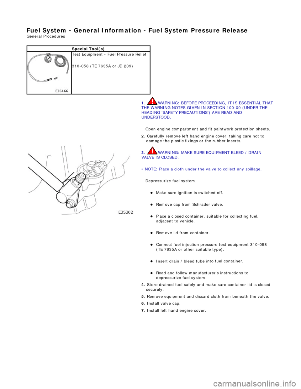
Fuel System - General Information - Fuel System Pressure Rele
ase
Gen
e
ral Procedures
S p
ecial Tool(s)
Tes
t
Equipment - Fuel Pressure Relief
310-058 (TE 7635A or JD 209)
1. WARNING: BEFORE PROCEEDING, IT IS ESSENTIAL THAT
THE WARNING NOTES GIVEN IN SECTION 100-00 (UNDER THE
HEADING 'SAFETY PRECAUTIONS') ARE READ AND
UNDERSTOOD.
Open engine compartment and fi t paintwork protection sheets.
2. Carefull
y remove left
hand engine cover, taking care not to
damage the plasti c fixings or the rubber inserts.
3. WA
RNING: MAKE SURE EQUIPMENT BLEED / DRAIN
VALVE IS CLOSED.
• NOTE: Place a cloth under the valve to collect any spillage.
Depressurize fuel system.
Make sure ignition i s
switched off.
R
e
move cap from Schrader valve.
Pla
c
e a closed container, su
itable for collecting fuel,
adjacent to vehicle.
R e
move lid from container.
Conne
ct
fuel injection pressu
re test equipment 310-058
(TE 7635A or other suitable type).
Insert drain / bleed tu be i
nto fuel container.
R
e
ad and follow manufacturer's instructions to
depressurize fuel system.
4. Store drained f u
el safely and make
sure container lid is closed
securely.
5. Remove equipment and discard cloth from beneath the valve.
6. Install valve cap.
7. Install left hand engine cover.
Page 1691 of 2490

Fuel System - Gener
al Information - Fuel Tank Draining
Gen
eral Procedures
1.
WARNING: BEFORE PROCEEDING, IT IS ESSENTIAL THAT
THE WARNING NOTES GIVEN IN SECTION 100-00 (UNDER THE
HEADING 'SAFETY PRECAUTIONS') ARE READ AND
UNDERSTOOD.
Remove the battery. Refer to operation 86.15.01.
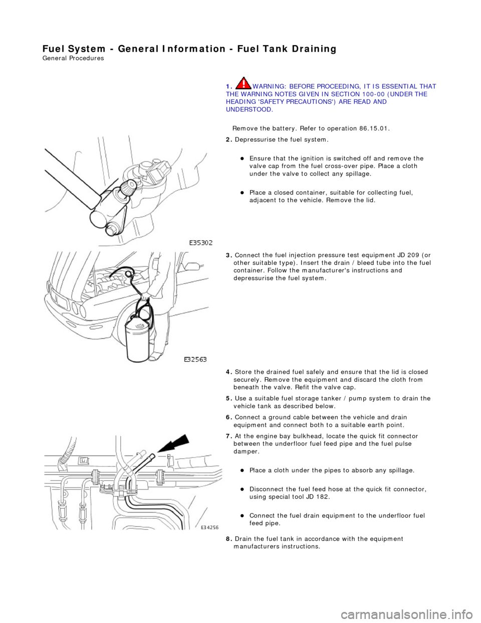
2. De
pressurise the fuel system.
E
nsure that the ignition is
switched off and remove the
valve cap from the fuel cross-over pipe. Place a cloth
under the valve to collect any spillage.
Pla
ce a closed container, su
itable for collecting fuel,
adjacent to the vehicle. Remove the lid.
3. Conne
ct the fuel injection pressu
re test equipment JD 209 (or
other suitable type). Insert the drain / bleed tube into the fuel
container. Follow the manufa cturer's instructions and
depressurise the fuel system.
4. Store the drained fuel safely and ensure that the lid is closed
securely. Remove the equipmen t and discard the cloth from
beneath the valve. Refit the valve cap.
5. Use a suitable fuel storage tank er / pump system to drain the
vehicle tank as described below.
6. Connect a ground cable betw een the vehicle and drain
equipment and connect both to a suitable earth point.
7. At the engine bay bulkhead, lo cate the quick fit connecto
r
between the underfloor fuel feed pipe and the fuel pulse
damper.
Pla
ce a cloth under the pipes
to absorb any spillage.
D
isconnect the fuel feed hose
at the quick fit connector,
using special tool JD 182.
Conne
ct the fuel drain equipment to the underfloor fuel
feed pipe.
8. Drain the fuel tank in accordance with the equipment
manufacturers instructions.
Page 1979 of 2490
Engine Management Fuse Box Relay
Engine Compartment - Front Relays
Engine and Transmission Control Module Compartment Relays
Relay NoColorCircuit
1BrownEMS control relay
Relay NoColorCircuit
1BlackWindshield wiper fast/slow
2BlackWindshield wiper on/off
Relay NoColorCircuit
1BlueSC coolant water pump
2BrownFuel injection main
3BrownIgnition coils
4BrownThrottle motor
5BrownStarter solenoid
6BrownAir conditioning compressor clutch
Page 2054 of 2490

Interior Trim and Ornamentation - Interior Trim
Description and Operation
Carpets
The passenger compartment carpet is a one piece moulded constr uction with integral sound deadening material, heel mats
and driver's footrest. The carpet is attach ed to the vehicle floor by plastic clips fitted below the door treadplates. Removal of the carpet necessitates re moval of the front seats, lifting of the centre console rear extens ion and removal of the heelboard
carpet.
Fascia
The full width, slush moulded, soft feel PVC fascia is mounted on an injection moulded armature and is faced with wood
veneer. In addition to the air conditioning and central, outer and demisting vents, it accepts instrument packs dedicated to
market requirements and a centrally mounted analogue clock.
Doors
The one-piece door casings are trimmed in UEV to match the seating, with wood veneer at the waistline and a carpet insert
at the front lower corner. Each casing is secured to the door inner panel by fir tree press fast eners along the lower section,
two armrest fixings at the centre and vene er panel dowels and fixings at the top. The armrests which are common to front
and rear doors, are trimmed in matching leather or UEV according to specification. The door switchpacks, dedicated to
driver and front or rear passenger, are in corporated in the armrests. A speaker is in stalled in the lower section of each door
and a tweeter is incorporated behind each interior door handle escutcheon. Where premium ICE is fitted, the front tweeters
are installed in the upper A posts.
A, B, C and D Posts
On each side,a grained UEV finisher trimmed to match the headlining is secured to the 'A' post and cantrail by fir tree
fasteners locating in BIW apertures. The upper 'D' post finisher is trimmed and secured in the same manner. The single
piece'B/C' post finishers, also finished in grained matching UEV, each have a front se at belt exit aperture and are secured to
the BIW by four spring clips and two fir tree fasteners.
Headlining
The one-piece headlining consists of a 6mm thick polyurethane foam membrane covered with suede effect knitted polyester. The headlining is secured to the BIW roof by body tangs, the roof console, sun visors, combined grab handles and coat
hooks, the cantrail finishers and where fitt ed, the sliding roof finisher and clips.
Trunk
Carpet covered trims line the trunk and are secured by fir tr ee fasteners to the sides and front inner panel. The carpet
covered, two-section, removable trunk fl oor provides access to the spare wheel and wheel changing equipment, the battery
and electrical carrier. The floor board rests on the spare wheel, with the front and rear edges locating in blocks on the fuel
tank backboard and the rear of the body. The support blocks provide for two floor he ight settings to accommodate either a
space saver or full size spare wheel.A moulded finisher covering the rear of the trunk below the sill is secured to the rear
panel by tabs and fir tree fasteners. Finish er panels fitted to the rear lamp units provide trunk interior access to the lamps.
The trunk lid underside is fitted with a removabl e moulded liner and two trunk illumination lights.
Page:
< prev 1-8 9-16 17-24