Page 1433 of 2490
Automatic Transmission/Transaxle - 4.0L SC V8 - AJ26 - Extension
Housing Seal
In-vehicle Repair
Removal
Special Tool(s)
Oil seal replacer
307-378
Driveshaft wrench
205-053
1. Disconnect the battery ground lead.
2. Select N and choc the road wheels.
3. Remove the front muffler, re fer to Operation 30.10.18.
4. Remove the engine rear mounting bracket.
1. Support the transmission.
2. Remove the bolt, engine rear mounting to transmission.
3. Remove the four bolts which secure the mounting
cross member to the body.
5. Detach the driveshaft from th e transmission drive flange.
1. If the transmission is to be refitted, mark the position of the coupling relative to the drive flange.
5. CAUTION: Under no circ umstances remove the
driveshaft to flexible coupling fixings.
2. Remove the three bolts, tr ansmission drive flange to
flexible coupling.
6. Secure the driveshaft wrench 205 - 053 to the output shaft
flange.
Page 1450 of 2490

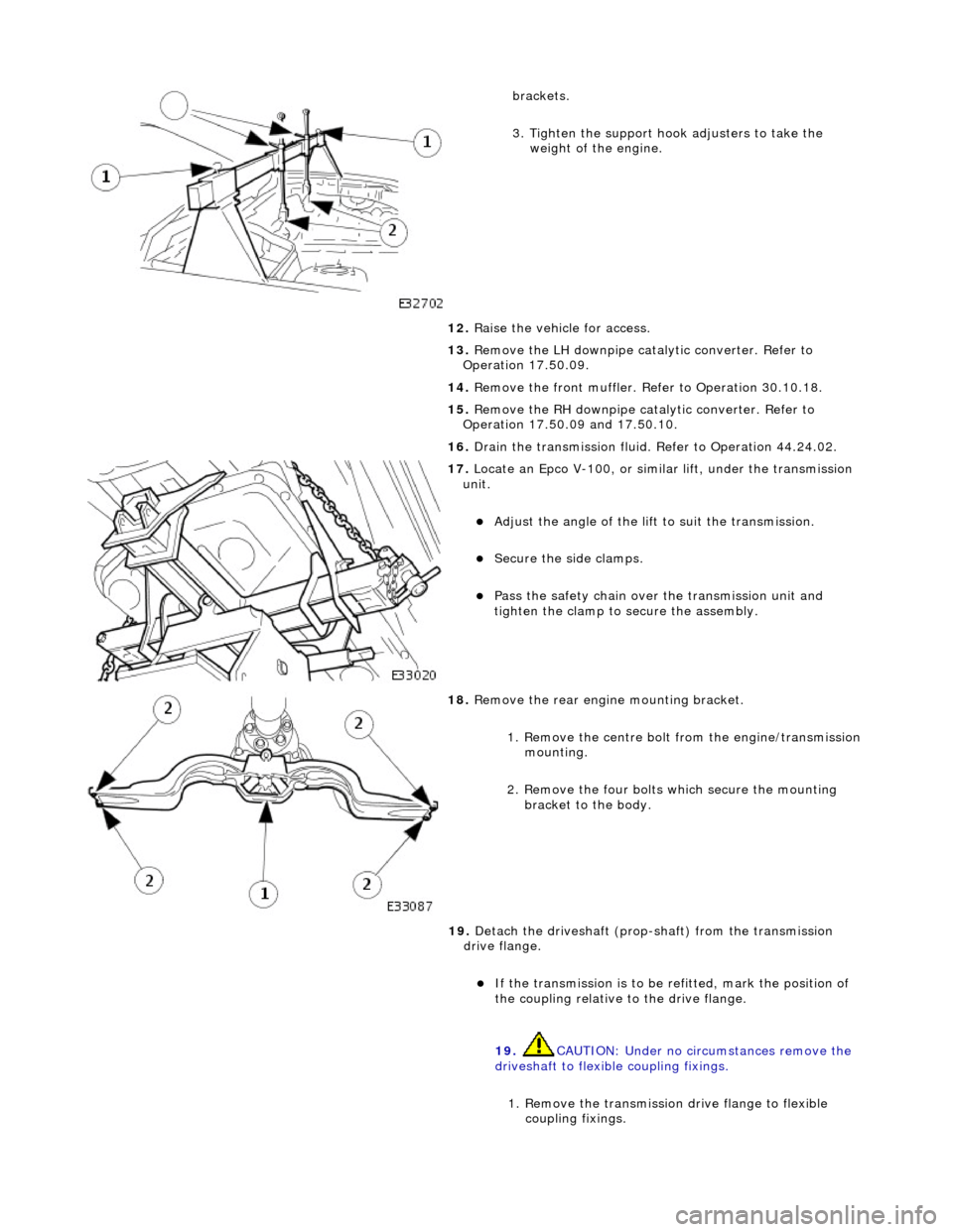
brackets.
3. Tighten the support hook adjusters to take the weight of the engine.
12. Raise the vehicle for access.
13. Remove the LH downpipe catalytic converter. Refer to
Operation 17.50.09.
14. Remove the front muffler. Re fer to Operation 30.10.18.
15. Remove the RH downpipe catalytic converter. Refer to
Operation 17.50.09 and 17.50.10.
16. Drain the transmission fluid. Refer to Operation 44.24.02.
17. Locate an Epco V-100, or sim ilar lift, under the transmission
unit.
Adjust the angle of the lift to suit the transmission.
Secure the side clamps.
Pass the safety chain over the transmission unit and
tighten the clamp to secure the assembly.
18. Remove the rear engine mounting bracket.
1. Remove the centre bolt from the engine/transmission
mounting.
2. Remove the four bolts which secure the mounting
bracket to the body.
19. Detach the driveshaft (prop- shaft) from the transmission
drive flange.
If the transmission is to be refitted, mark the position of
the coupling relative to the drive flange.
19. CAUTION: Under no circ umstances remove the
driveshaft to flexible coupling fixings.
1. Remove the transmission drive flange to flexible
coupling fixings.
Page 1460 of 2490
10. Refit the harness connector support bracket and tighten the
two bolts to the specified torque figure, noting that one fixing
also retains the di pstick upper tube.
11. Connect the selector cable. Ti ghten the bolts and one nut to
the specified torque figure.
12. Connect the driveshaft (prop-shaft) aligning the marks made
when it was removed. Tighten the bolts to the specified torque
figure.
13. Fit the rear crossmember. Tighten the bolts to the specified
torque figure.
Page 2387 of 2490
Key to Plan
Standard Wheelbase Body Dimensions- Side View
KeyLocation
1Front face body-bumper strut/mounting point
2Rearmost hole, vee-mount to crush tube
3Front Master Datum Plan, centre li ne of front crossmember rear mount ing at main floor RH longitudinal
4Rearmost hole, transmission mounting at main floor RH longitudinal
5Handbrake rear lever bracket fixings
6Rear Master Datum Plan, rear longitudinal
7Tapped boss, rear suspension 'A' frame mounting bush
8Rear suspension spring-pan damper mounting
9Rear suspension differential strut mounting
10Rear face body-bumper strut/mounting point
11Driveshaft centre bearing mounting
Page 2388 of 2490
Key to SideView
Long Wheelbase Body Dimensions-Plan
KeyLocation
1Front face body-bumper strut/mounting point
2Front Master Datum Vertical, centre line of front crossmember rear mounting
3Transmission mountings at the main floor longitudinal
4Handbrake rear lever bracket fixings
5Rear Master Datum Vertical,, rear longitudinal
6Tapped boss, rear suspensi on 'A' frame mounting bush
7Rear suspension spring-pan damper mounting
8Rear suspension differential strut mounting
9Rear face body-bumper strut/mounting point
10Wheel centre to bumper cover face
11Wheelbase
12Wheel Centre to Bumper Cover Face
13Driveshaft centre bearing mounting
Page 2389 of 2490
Key to Plan
Long Wheelbase Body Dimensions- Side View
KeyLocation
1Front face body-bumper strut/mounting point
2Rearmost hole, vee-mount to crush tube
3Front Master Datum Plan, centre line of front crossmember rear mount ing at main floor RH longitudinal
4Rearmost hole, transmission mounting at main floor RH longitudinal
5Handbrake rear lever bracket fixings
6Rear Master Datum Plan, rear longitudinal
7Tapped boss, rear suspension 'A' frame mounting bush
8Rear suspension spring-pan damper mounting
9Rear suspension differential strut mounting
10Rear face body-bumper strut/mounting point
11Driveshaft centre bearing mounting
Page 2390 of 2490
Key to SideView
KeyLocation
1Front face body-bumper strut/mounting point
2Front Master Datum Vertical, centre line of front crossmember rear mounting
3Transmission mountings at the main floor longitudinal
4Handbrake rear lever bracket fixings
5Rear Master Datum Vertical,, rear longitudinal
6Tapped boss, rear suspensi on 'A' frame mounting bush
7Rear suspension spring-pan damper mounting
8Rear suspension differential strut mounting
9Rear face body-bumper strut/mounting point
10Wheel centre to bumper cover face
11Wheelbase
12Wheel Centre to Bumper Cover Face
13Driveshaft centre bearing mounting
Page:
< prev 1-8 9-16 17-24