Page 1688 of 2490
Fuel System - General Inform
ation - Fuel System
Description an
d Operation
The fuel tank is mounted across the vehicle behind the passenger compartment bulkhead.
Fuel is drawn by the fuel pump from the tank and then supplied to the two fuel rails, via a filter.
Fuel injectors are installed in the fuel ra ils on each side of the intake manifold.
The amount of fuel injected into th e engine is controlled by the ECM.
A cross-over pipe connects the two fuel ra ils together at the front of the manifold.
A test valve in the cross-over pipe allo ws the fuel rail to be pressurized and de-pressurized during the servicing and
troubleshooting procedures.
A pressure regulator on the rear of the right fuel rail controls the pressure in the fuel rails.
A return line directs excess fuel from the pressure regulator back to the fuel tank.
Operation and service procedures
The fuel injector
s, rails, pres
sure regulator and, wher e fitted, supercharger are described in greater detail in Section 303-04
together with servicing procedures.
The fuel tank, pump, fuel level senders and fuel lines are similarly covered in Section 310-01.
Page 1692 of 2490
Fuel Tank and Lines - Fuel Tank and Li
nes
Description an
d Operation
Fuel Tank
Parts List
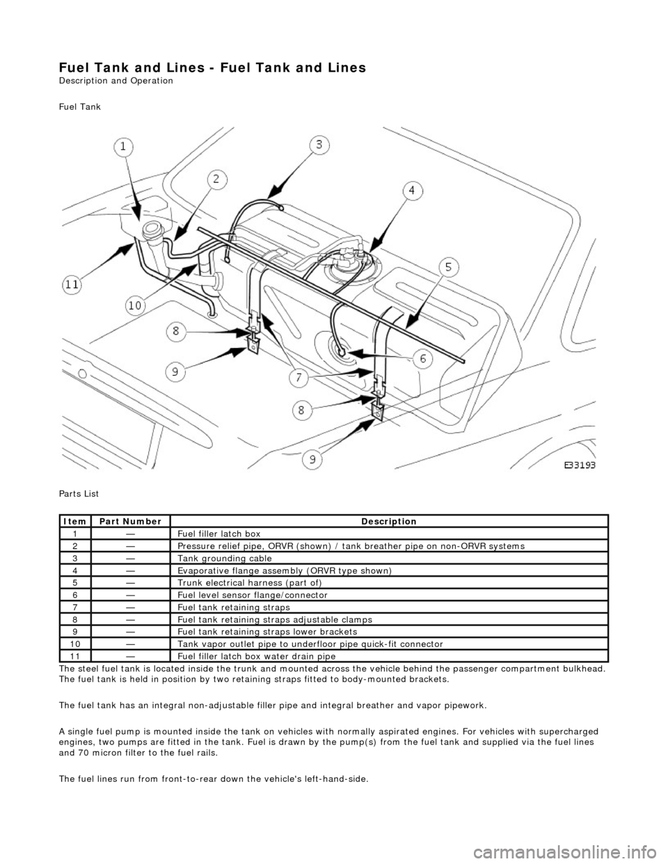
The steel fuel tank is located inside the trunk and mounted across the vehicle behind the passenger compartment bulkhead.
The fuel tank is held in posi tion by two retaining straps fi tted to body-mounted brackets.
The fuel tank has an integral non-adjustable fill er pipe and integral breather and vapor pipework.
A single fuel pump is mounted inside the tank on vehicles with normally aspirated engines. For vehicles with supercharged
engines, two pumps are fitted in the tank. Fuel is drawn by the pump(s) from the fuel tank and supplied via the fuel lines
and 70 micron filter to the fuel rails.
The fuel lines run from front-to-rear down the vehicle's left-hand-side.
Ite
m
Part
Number
Descr
iption
1—Fu
el filler latch box
2—Pressure reli
ef pipe, ORVR
(shown) / tank breather pipe on non-ORVR systems
3—Tank grounding
cable
4—Evaporative flan
ge assembly
(ORVR type shown)
5—Trunk elec
trical harne
ss (part of)
6—Fue
l
level sensor
flange/connector
7—Fu
el tank retaining straps
8—F
u
el tank retaining stra
ps adjustable clamps
9—Fu
el tank retaining straps lower brackets
10—Tank vapor outlet pipe to un
derflo
or pipe quick-fit connector
11—F
u
el filler latch bo
x water drain pipe
Page 1698 of 2490
Fuel Tank and Lines - Fuel Tank and Li
nes
D
iagn
osis and Testing
Sym
p
tom Chart
Sy
m
ptom Chart
Pinpoint test A: P1230
S
p
ecial Tool(s)
D
i
gital multimeter
Generi
c scan tool
F
u
el tank sender (sensor) unit wrench
18G 1001
Sy m
ptom
Possib
l
e Sources
Acti
o
n
D
T
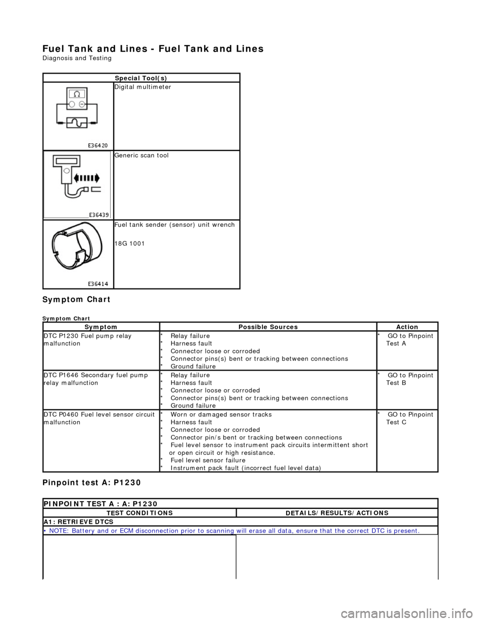
C P1230 Fuel pump relay
malfunction
Re lay
failure
Harness fault
Connector loose or corroded
Connector pins(s) bent or tracking between connections
Ground failure
*
*
*
*
*
GO to Pinpoint
Test A
*
D
T
C P1646 Secondary fuel pump
relay malfunction
Re lay
failure
Harness fault
Connector loose or corroded
Connector pins(s) bent or tracking between connections
Ground failure
*
*
*
*
*
GO to Pinpoint
Test B
*
D
T
C P0460 Fuel level sensor circuit
malfunction
Worn
or damaged sensor tracks
Harness fault
Connector loose or corroded
Connector pin/s bent or tracking between connections
Fuel level sensor to instrument pack circui ts intermittent short
or open circuit or high resistance. Fuel level sensor failure
Instrument pack fault (inc orrect fuel level data)
*
*
*
*
*
*
*
GO to Pinpoint
Test C
*
P
INPOINT TES
T A : A: P1230
T
E
ST CONDITIONS
D
E
TAILS/RESULTS/ACTIONS
A1
: RETRIEV
E DTCS
•
NOTE
: Battery and or ECM disconnection prior to scanning wi
ll erase all data, ensure that the correct DTC is present.
Page 1732 of 2490
Fu
el Tank and Lines - Fuel Level Sensor
Remov
a
l and Installation
Removal
Ins
tallation
1.
WA
RNING: BEFORE PROCEEDING, IT IS ESSENTIAL THAT THE
WARNING NOTES GIVEN IN SECTIO N 100-00 (UNDER THE HEADING
'SAFETY PRECAUTIONS') ARE READ AND UNDERSTOOD.
Remove the battery. For additional information, refer to Section 414
-01
Battery, Mounting and Cables
.
2.
Drain
the fuel tank using a suitable suction pump/tanker. If the On-
board Refueling Vapour Recovery (ORVR) system is fitted, refer to
Section 310
-00 Fu
el System
- Gen
e
ral Information
.
3. Remov
e the trunk front liner. For additional information, refer to
Section 501
-05 Interior Trim
and Ornamentation
.
4. D
isconnect the harness co
nnections to the sensor.
5. U
sing special tool 18G 1001, remo
ve the sensor retaining ring.
6.
Remov
e the sensor assembly and discard the seal.
1. Fitting a new level sensor is the reverse of the removal procedure,
noting that a new seal must be fitted.
Page 1734 of 2490
Fuel Tank and Lines - Fuel Tank
Re
mo
val and Installation
Remov
a
l
•
NO
TE: This removal/installation procedure is applicable to all tank assembly variants.
S
p
ecial Tool(s)
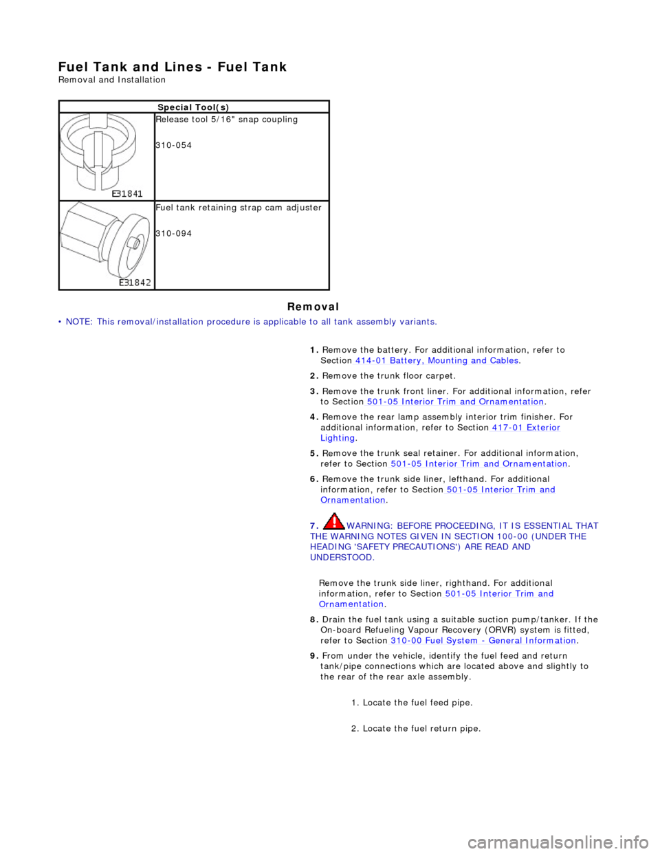
R
e
lease tool 5/16" snap coupling
310-054
F u
el tank retaining strap cam adjuster
310-094
1. Remove the battery. For additi onal information, refer to
Section 414
-01
Battery, Mounting and Cables
.
2. Re
move the trunk floor carpet.
3. Remove the trunk front liner. Fo r additional information, refer
to Section 501
-05
Interior Trim and Ornamentation
.
4. Re
move the rear lamp assembly interior trim finisher. For
additional information, refer to Section 417
-01
Exterior
Ligh
ting.
5. Re
move the trunk seal retainer
. For additional information,
refer to Section 501
-0 5
Interior Trim and Ornamentation
.
6. Re
move the trunk side liner, lefthand. For additional
information, refer to Section 501
-05
Interior Trim and
Or
n
amentation
.
7. WARNING: B E
FORE PROCEEDING, IT IS ESSENTIAL THAT
THE WARNING NOTES GIVEN IN SECTION 100-00 (UNDER THE
HEADING 'SAFETY PRECAUTIONS') ARE READ AND
UNDERSTOOD.
Remove the trunk side liner, righthand. For additional
information, refer to Section 501
-05
Interior Trim and
Or
n
amentation
.
8.
Drain th e fue
l tank using a suitab
le suction pump/tanker. If the
On-board Refueling Vapour Recove ry (ORVR) system is fitted,
refer to Section 310
-00 Fu
el System
- General
Information
.
9. Fr
om under the vehicle, identify the fuel feed and return
tank/pipe connections which are located above and slightly to
the rear of the rear axle assembly.
1. Locate the fuel feed pipe.
2. Locate the fuel return pipe.
Page 2417 of 2490
Panels centered between two adjacent panels must have equal gaps on either side. For exceptions to this, refer to the
appropriate specification. Gaps between ad jacent panels or components must not expose harnesses, labels, brackets or
visually poor joint or assembly conditions.
• NOTE: Sliding roof panel clearances are specified without the edge seal installed.
Areas of particular concern are, fuel filler flap, trunk lid to fenders and saddle panels, hood to fenders, grill and headlamps,
sliding roof to main roof panel, door gaps at fenders, B\C posts, roof drip rail an d rocker panel, and bumper cover to fenders
and cross car assemblies
Alignment
Panels must be correctly profiled to maintain cosmetic appearance, and ensure co rrect seating of seals with minimal wind
noise. Areas of particular concern are hood to fenders, trunk lid to fenders and saddle panels, doors to apertures, doors to
fenders and adjacent doors and relationship of the sliding roof panel leading and trailing edges to the main roof panel.
Exterior Fitments
Bezels, trims and lamps must be concentric with apertu res and have equal clearances with adjacent panels.
Areas of particular concern are headlamp to hood, fender and trim panel, exhaust tailpipe trim to bumper cover cut-out,
rear lamp assembly to trunk lid, fender and bumper cover trim, and side feature lines including body side mouldings, fender
to door and door to door.
Exterior Clearances and Alignments-Front
Page:
< prev 1-8 9-16 17-24