1998 JAGUAR X308 wheel
[x] Cancel search: wheelPage 508 of 2490

The te
lescopic slider provides driver crash
protection by retracting automatically in the event of an accident; it is clamped in
position to a preset torque.
The motorized upper steering column has the following serviceable parts:
Igniti
on switch assembly.
Igni
ti
on key interlock solenoid.
Ti
lt
motor assembly.
Reach motor assembly.
Manu al Upper Column Assembly
Ite
m
Par
t
Number
De
scr
iption
1-L
o
wer mounting bracket
2-Crash tube
3-Harnes
s c
onnector bracket
4-Tilt motor
5-Reach m
otor
6-Upper
moun
ting bracket
7-Ignition switc
h
(hidden)
8-Igni
ti
on key interlock solenoid
9-S
t
eering wheel mounting shaft
It
e
m
Par
t
Number
De
scr
iption
1-Upper
cowl
2-Lower cowl
3-Colu
mn tilt adjustment lever
4-Col
u
mn reach adjustment lever
5-Di
mm
er switch
Motorized Upper Co
lumn Components
Page 509 of 2490

Is adjustable for both til
t and reach.
Has ca
ble operated reach adjustment, using a rack an
d wedge, with approximately 16 latched positions.
Has si
x latched tilt positions steppe
d at approximately 3° intervals.
Has an u
nlatched top tilt position, allowing the column to be
pulled down to engage the first detent without using the
tilt lever.
Has an instrument li
ghti
ng dimmer switch installed on the left-hand side of the lower cowl.
Manual Upper Column Components
The telescopic slider provides driver crash protection by retracting automatically in the event of an accident; it is clamped in
position to a preset torque.
The manual upper steering column has the following serviceable parts:
Igni
tion switch assembly.
Igni
tion key interlock solenoid.
Bowden
cable and lever assembly.
It
em
Par
t Number
De
scription
1-L
ower mounting bracket
2-Crash tube
3-Harnes
s connector bracket
4-Upper
mounting bracket
5-Ignition switc
h (hidden)
6-Igni
tion key interlock solenoid
7-S
teering wheel mounting shaft
The manu
al upper
steering column:
Page 517 of 2490

o
perating. If an indicator bulb fails, the warning
lamp and ticking operate at twice the normal rate.
Sidelam
ps and Headlamps
Thes
e are controlled by rotating the end of the column switch as follows.
In the OFF position:
All
exterior lamps are switched OFF.
In the sidelamp position:
The front
sidelamps, tail, license plate and any other la
mps required by local legislation are switched ON.
The
sidelamps tell-tale lamp illuminates.
In the headlamp position, with the ignition switch in position II:
The h
eadlamps are switched ON in addition to the lamps switched on in the sidelamp position.
If the ignition is switched to the OFF position with the column switch in the headlamp position, the sidelamps, tail and
license plate lamps will stay ON, but the headlamps will switch OFF.
In the AUTO position (where fitted), with the ignition switch in position II:
Th
e sensor mounted on the back of the interior rear view
mirror monitors exterior light levels and automatically
switches the sidelamps and di pped headlamps ON and OFF.
The sensitivity level can be adjusted by turn ing the sensor control knob on the back of the interior mirror, left to decrease or
right to increase. The sensor must not be covered and the windscreen must be kept clean.
Headlamp Main Bea
m Position
Wi
th the column switch in
the headlamp position:
Movin
g the switch stalk away fro
m the steering wheel switches the headlamps to main beam.
Movin
g the switch stalk towards the steering wheel switches the headlamps to dipped beam.
The main beam tell-tale lamp illuminates when the headlamps are switched to main beam.
Ma
in Beam Flash
Wi
th the ignition switch and column switch in any position:
Pulling the
switch stalk agains
t spring pressure towards th e steering wheel illuminates the headlamps on main beam
for as long as the switch is held.
The main beam tell-tale lamp illuminates while the headlamps are illuminated.
M
essage Center Functions
T
he message center functions:
Are se
lected by the button located at the end of the lighting switch stalk.
Are se
lected in turn, by repeatedly pressing the button,
from the odometer reading, through the trip computer data
in sequence, and back to th e odometer reading again.
Page 518 of 2490

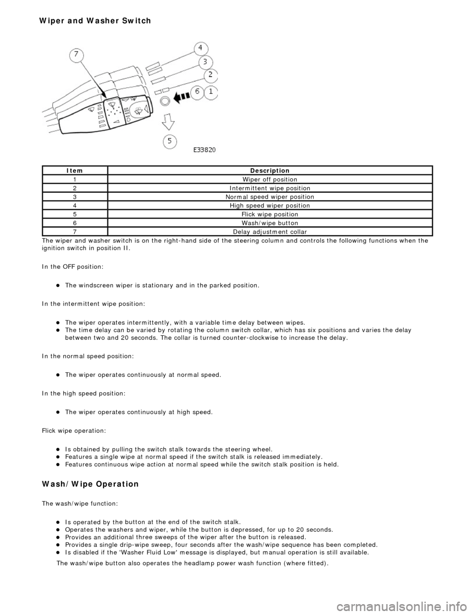
The wiper and washer switch i s
on the righ
t-hand side of the steering column and controls the fo llowing functions when the
ignition switch in position II.
In the OFF position:
The windscreen wiper is stationary and in the parked positio
n.
In the intermittent wipe position:
The wi per ope
rates intermittently, with
a variable time delay between wipes.
The time del
ay can be varied by rotating the column sw
itch collar, which has six positions and varies the delay
between two and 20 seconds. The collar is turned counter-clockwise to increase the delay.
In the normal speed position:
The wiper oper a
tes continuously at normal speed.
In the high speed position:
The wiper ope r
ates continuously at high speed.
Flick wipe operation:
Is obt
ained by pulling the switch
stalk towards the steering wheel.
F
e
atures a single wipe at normal speed if
the switch stalk is released immediately.
Fe
atures continuous wipe action
at normal speed while the swit ch stalk position is held.
Wash/W
ipe Operation
Th
e
wash/wipe function:
Is operat
ed by th
e button at the end of the switch stalk.
Op
erate
s the washers and wiper, while the butt
on is depressed, for up to 20 seconds.
Provides an addit
ional three sweeps of
the wiper after the button is released.
Provid
es a single drip-wipe sweep, four seconds af
ter the wash/wipe sequence has been completed.
Is disabled if the 'Washer Flu
id Low' message is di
splayed, but manual operat ion is still available.
Ite
m
De
scr
iption
1W
i
per off position
2Intermittent
wipe position
3Normal
speed wiper position
4High
speed wiper position
5Flick wipe position
6Wa
sh/wipe button
7D
e
lay adjustment collar
The was
h
/wipe button also operates the head
lamp power wash function (where fitted).
Wiper and Washer Switch
Page 519 of 2490

Steering Column Switches - Steering Colu
mn Multifunction Switch
Re
moval and Installation
Remov
al
Installation
1.
D
isconnect battery ground cable; refer to 86.15.19.
2. NOTE: Steering wheel must be in the straight ahead position.
Remove steering wheel.
3. Di
splace cancellation module connector from mounting bracket
and disconnect.
4. Di
splace flasher/headlamp/t
rip switch connectors from
mounting bracket and disconnect.
Cut an
d remove appropriate harness securing ties.
5. Re
move switchgear.
1. Remove two screws which secure switch assembly/cancellation module to mounting bracket.
2. Displace switchgear from mounting bracket.
3. Route switchgear harness through mounting bracket and remove switchgear.
1. Installation is reverse of removal.
Page 528 of 2490

Speed an
d load
Coo
l
ant temperature
Ti
me el
apsed from start up
Cl
osed l
oop fuelling
Determination of the vapour concentration is made by stepped opening of the EVAP valve and subsequent monitoring of the
fuelling correction. This function is performed prior to purging, so that at the onse t of purging the EVAP valve can be set to
the optimum position. Should the ECM be unable to determine the concentration before purging, a default value is
employed, which is then modified whilst purging is in progress.
When the purging process is operational th e ECM modifies the basic fuelling calculation to maintain the correct air / fuel
ratio.
Purging is inhibited during fuel cut-off and stability / traction control intervention.
Coolant Temperature Sen
sor
Th
e
sensor outputs a voltage to the ECM which decreases as temperature increases.
Cooling Fans
In response to engi
ne coolant temperat
u
re and climate control system demand, the ECM will energize the cooling fans.
Climate Control Compressor
The E
C
M will allow the compressor clutch to be engaged if th
e engine temperature and load demand are normal. Should the
driver require maximum engine powe r or the coolant temperature be high, the request will be denied.
Cranking Signal
The ECM reacts to a signal fr
om th
e Body Processor Module (BPM) when the starter motor relay is energi
zed. This signal is
used to trigger starting, fu el and ignition strategies.
Engine Speed and Cranksh
aft Position
Engine
speed and cran
k position are moni
tored by a sensor which is mounted on the cylinder block (flywheel housing)
behind the crankshaft drive plat e. It indicates rotational speed to the ECM in the form of 12 pulses per crank revolution.
Engine speed is used for synchronization of fuel an d ignition systems, as well as other functions.
Camshaft Position
The ca
mshaft position sensor is mounted at
the rear of Bank 2 cylinder head on the inlet side and provides one signal every
720 degrees of crankshaft rotation. The signal, in conjunction with the signal from the crankshaft position sensor, indicates
to the ECM that the piston of cylinder 1A is approaching TDC on the compression stroke.
Variable Valve
Timing (Where Fitted)
By energi
si
ng a solenoid to allow the pass
age of pressurized oil on each of the inle t camshaft drives, the ECM can vary by a
single stepped amount, the relati ve timing of the inlet valves.
Ign
ition
Ignit
i
on spark is produced by
individual on-plug coil units.
There are two ignition amplifiers; module #1 drives coils 1A, 2B, 3B and 4A, whilst module #2 drives coils 1B, 2A, 3A and
4B. The ECM controls the amplifiers.
Page 530 of 2490

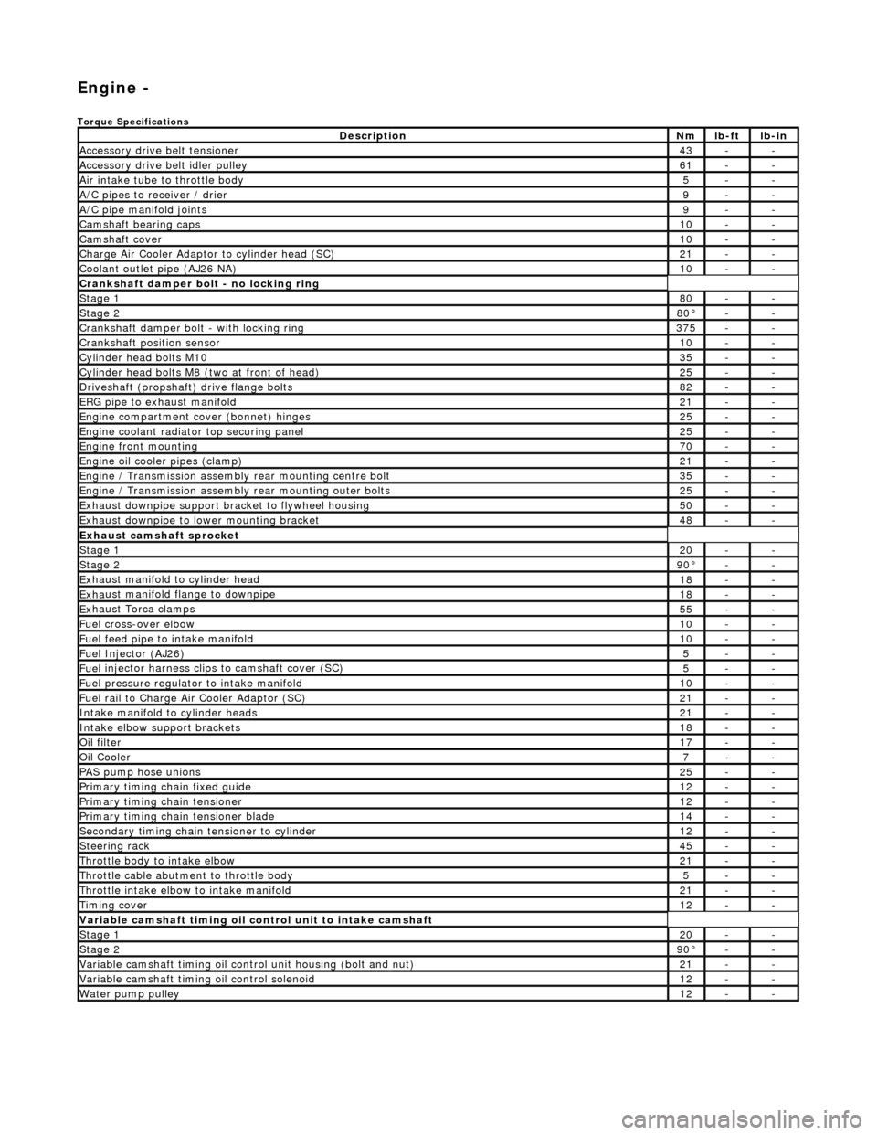
Engi
ne -
Torqu
e Specifications
De
s
cription
Nmlb
-
ft
lb
-
in
A
ccessory
drive belt tensioner
43--
A
ccessory
drive belt idler pulley
61--
Air in
ta
ke tube to throttle body
5--
A/C
pipes t
o receiver / drier
9--
A/C pipe m
anifold joints
9--
Camsh
aft bearin
g caps10--
Ca
msh
aft cove
r10--
Ch
arge Air Co
oler Adaptor to cylinder head (SC)
21--
Co
olan
t outlet pipe (AJ26 NA)
10--
Cran
kshaft damper bolt - no lockin
g ring
St
ag
e 1
80--
Stag
e 2
80°--
C
r
ankshaft damper bolt - with locking ring
37
5--
Cra
nkshaft position sensor
10--
Cy
li
nder head bolts M10
35--
Cy
lin
der head bolts M8 (two at front of head)
25--
Driv
es
haft (propshaft) drive flan
ge bo
l
ts
82--
ERG p
i
pe to exhaust manifold
21--
Engi
ne compartment cover (bonnet) hinges
25--
En
gine
coolant radiator top securing panel
25--
E
ng
ine front mounting
70--
En
gine
oil cooler pipes (clamp)
21--
En
gi
ne / Transmission assembly rear mounting centre bolt
35--
En
gi
ne / Transmission assembly rear mounting outer bolts
25--
Ex
ha
ust downpipe support bracket to flywheel housing
50--
Ex
ha
ust downpipe to lower mounting bracket
48--
E
x
haust camshaft sprocket
St
age 120--
Stage 290 °--
Ex
haust manifold to cylinder head
18--
Ex
ha
ust manifold flange to downpipe
18--
E
x
haust Torca clamps
55--
Fuel cross-over elbo
w
10--
Fu
el f
eed pipe to intake manifold
10--
Fuel
Injector (AJ
26)
5--
Fuel
injector ha
rness clips to camshaft cover (SC)
5--
Fu
el p
ressure re
gu
l
ator to intake manifold
10--
F
u
el rail to Char
ge
A
ir Cooler Adaptor (SC)
21--
In
ta
ke manifold to cylinder heads
21--
Inta
ke elbow support brackets
18--
Oil f
i
lter
17--
Oil C
o
oler
7--
P
AS pu
mp hose unions
25--
P
r
imary timing chain fixed guide
12--
P
r
imary timing chain tensioner
12--
Pr
imary timing chain tensioner blade
14--
S
e
condary timing chain tensioner to cylinder
12--
S
t
eerin
g ra
ck45--
Thro
ttle body to intake elbow
21--
Th
ro
ttle cable abutment to throttle body
5--
Th
ro
ttle intake elbow to intake manifold
21--
Ti
mi
ng cover
12--
Variable camshaft t
i
ming oil control unit to intake camshaft
St
ag
e 1
20--
St
ag
e 2
90
°--
Var
iable camshaft timing oil control unit housing (bolt and nut)
21--
Va
ria
ble camshaft timi
ng oil control solenoid
12--
Wa
ter pump pulley
12--
Page 552 of 2490

Engine - Connecting Rod Bearings
In-vehic
le Repair
Remov
a
l
1.
Disc
onnect the batt
ery ground cable.
Re
move the battery cover.
2. Open the engine compartment and fit paintwork protection
sheets.
3. Remove the engine compartmen t cover. Refer to operation
76.16.01.
4. Remove the twin fan and motor assembly. Refer to Operation
26.25.12.
5. Remove the timing cover and al l associated components, as
detailed in Operation 12.65.01.
6. Remove both front wheel and tyre assemblies. Refer to
Operation 74.20.05.
7. Remove the undertray. Re fer to Operation 76.22.90.
8. Remove the front crossmember fo r access. Refer to Operation
76.10.05.
9. Drai
n the engine oil.
1. Position the waste oil bowser.
2. Remove the drain plug from the oil pan and drain the engine oil.
Install a new sealing wash er to the
drain plug.
Wipe the drain plug an
d
install
it to the oil pan to prevent
oil dripping.
Move the oil bowser away f
rom the vehicle.
10 . Re
move the oil pan.
1. Remove the eighteen bolt s which secure the oil pan
to the oil pan body.
2. Remove the oil pan.
3. Remove the gasket from the oil pan body assembly.
11. Remove the oil pan body a ssembly. Refer to Operation