1998 JAGUAR X308 speed
[x] Cancel search: speedPage 2112 of 2490
Mirror adjustment can only be made when the ignition switch is in position I or II or the driver's door is open, and the
selector switch is moved from the central position.
When fitted, electrochromic door mirrors au tomatically darken under control of the interior rear view mirror. Mirror heating
elements operate on selection of backlight heating.
Automatic dipping of passenger door mirror for kerb view when reversing, is fitted as part of the memory pack. With the
ignition switch in position II, the mirror selector switch in the left or right position and reverse gear selected, automatic
dipping is initiated by moving the mirro r toggle switch rearwards and releasing.
On receipt of the dip signal, th e passenger door mirror is driven downwards eith er 7 degrees, bottom of travel, or 4,5 to 5,5
seconds, whichever occurs first. Subsequent rear ward movement of the toggle switch achieves further dipping of the mirror
in the same increments and sequence.
The mirror can be manually returned to the normal memorised position by moving the toggle switch forward with reverse
gear selected. The mirror will automatically return to memorised position on deselection of reverse gear, or moving ignition
switch from position II.
Door mirror fold-back where fitted, to facilitate parking in conf ined spaces, can be initiated when the ignition switch is in
position I or II, the mirror selector switch is in the centra l position and vehicle speed is below 19 km/h (12 mph). Mirror
fold-back is then initiated by moving the toggle switch rear wards and releasing it. The door mirrors are returned to the
normal driving position by ag ain moving toggle switch rearwards. There is no speed constraint on this operation.
In the event of a fold-back mirror becoming 'out of position' du e to accidental impact, it must only be re-positioned by
initiating the fold-back sequence.
Loss of power supplies will result in loss of mirror fold-back memory. In the event of such a memory loss with mirrors in the
normal position, fold-back will operate on second movement of the toggle swit ch. On loss of memory with mirrors in the
fold-back position, they will return to the no rmal position on next fold-back operation.
Page 2273 of 2490
Handles, Locks, Latches and Entry Systems - Handles, Locks, Latches and
Entry Systems
Description and Operation
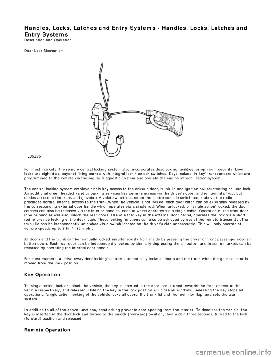
Door Lock Mechanism
For most markets, the remote central locking system also, in corporates deadlocking facilities for optimum security. Door
locks are eight disc, bayonet fixing barrels with integral lock / unlock switches. Keys include 'in-key' transponders which are
programmed to the vehicle via the Jaguar Diagnostic Sy stem and operate the engine immobilisation system.
The central locking system employs single key access to the driv er's door, trunk lid and ignition switch/steering column lock.
An additional green headed valet or park ing services key permits access via the driver's door, and ignition/start-up, but
denies access to the trunk and glovebox.A valet switch located on the centre console switch panel above the radio,
precludes normal internal access to the trunk.When the vehicle is not locked, each door catch can be externally released by
the corresponding external door handle which operates via a si ngle rod. When unlocked, or 'single action' locked, the door
catches can also be released via the interior handles, each of which operates via a single cable. Operation of the front door
interior handles will also unlock the rear doors. Use of either key in the external door barrel, operates the lock via a short
rod to provide locking of the door latch. These locking functions can also be achieved by use of the remote transmitter.The
trunk lid can be independently unlatched via a switch located on the driver's side underscuttle. This will only operate at
vehicle speeds up to 8 km/h (5 mph).
All doors and the trunk can be manually lock ed simultaneously from inside by pressing the driver or front passenger door sill
button down. Each rear door can be independently locked by si milarly depressing the sill button and in some markets can be released by operating the internal door handle.
For most markets, a 'drive-away door locking' feature automati cally locks all doors and the trunk when the gear selector is
moved from the Park position.
Key Operation
To 'single action' lock or unlock the vehicle, the key is inserted in the door lock , turned towards the front or rear of the
vehicle respectively, and released. Holding the key in the lock position will close all windows. Releasing the key stops all
operations. 'single action' locking of the vehicle locks all doors, the trunk lid and the fuel filler flap, and sets the alarm
system.
In addition to all of the above functions, deadlocking prevents door opening from th e interior. To deadlock the vehicle, the
key is inserted in the door lock and turned to the unlock (rearw ard) position, then within three seconds, turned to the lock
(forward) position and released.
Remote Operation
Page 2306 of 2490
Wipers and Washers - Wipers and Washers
Description and Operation
Windshield Wiper
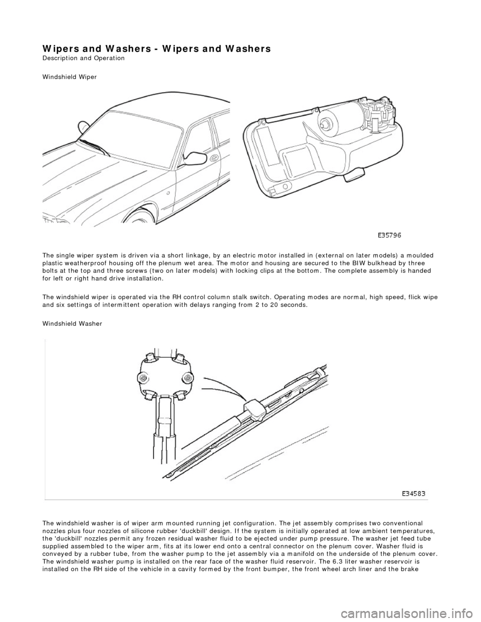
The single wiper system is driven via a sh ort linkage, by an electric motor installed in (external on later models) a moulded
plastic weatherproof housing o ff the plenum wet area. The motor and housing are secured to the BIW bulkhead by three
bolts at the top and three screws (two on later models) with locking clips at the bottom. The complete assembly is handed
for left or right hand drive installation.
The windshield wiper is operated via the RH control column stalk switch. Operating modes are normal, high speed, flick wipe
and six settings of intermittent operation with delays ranging from 2 to 20 seconds.
Windshield Washer
The windshield washer is of wiper arm mounted running jet configuration. The je t assembly comprises two conventional
nozzles plus four nozzles of silicone rubbe r 'duckbill' design. If the system is initially operated at low ambient temperatures ,
the 'duckbill' nozzles permit an y frozen residual washer fluid to be ejected un der pump pressure. The washer jet feed tube
supplied assembled to the wiper ar m, fits at its lower end onto a central connector on the pl enum cover. Washer fluid is
conveyed by a rubber tube, from the washer pump to the jet assembly via a manifold on the underside of the plenum cover.
The windshield washer pump is installed on the rear face of the washer fluid reservoir. The 6.3 liter washer reservoir is
installed on the RH side of th e vehicle in a cavity formed by the front bu mper, the front wheel arch liner and the brake
Page 2309 of 2490
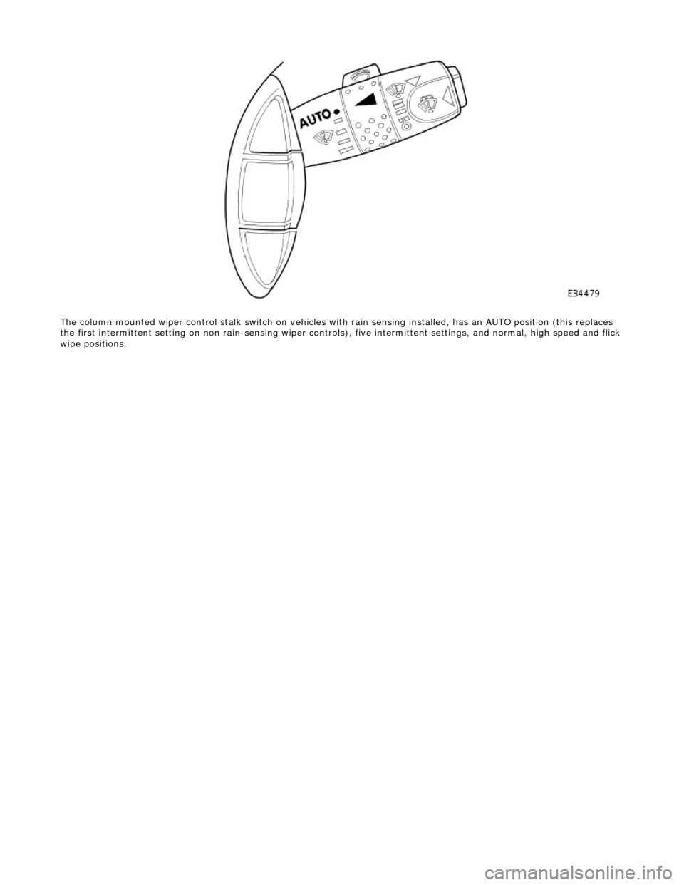
The column mounted wiper control stalk switch on vehicles with rain sensing installed, has an AUTO position (this replaces
the first intermitte nt setting on non rain-sensing wiper controls), five intermittent settings, and normal, high speed and flick
wipe positions.
Page 2410 of 2490
GLAZING
In order that the design condition of the vehicle is preserved when direct glazing repairs are carried out, it is essential that
only approved materials an d processes are employed.
Glass and Body Preparation
Betaseal HV3 System methods an d materials, are used on all Jaguar vehicles . Ease of working and extended process time
can however be gained by ensuring that the vehicle body and replacement glass are at a minimum room temperature of 20°
C prior to adhesive a pplication and fitting.
In the event of damage to the body flange finish, rectify as appropriate with the full paint refinishing process as described in
the Paint Refinishing Manual.
Adhesive Application Temperature
The specified adhesive has a high viscosity and is not easily applied at 'room te mperature' using conventional methods.
When the adhesive is applied it chills ra pidly on contact with the body and reverts to the hard condition, providing retention
strength with in minutes.
Raising the temperature of the adhesive will reduce viscosity an d speed up the flow. It is recommended that the adhesive is
pre-warmed in a heated cabinet for a mini mum of twenty minutes and applied with an extrusion gun incorporating integral
heating elements.
Adhesive Application
CAUTION: The glass will not bond to the body if the time taken to apply the adhesive and position the glass, exceeds
the stated limit.
It is recommended that the be ad of adhesive conforms to the shape and dimensions shown in the Adhesive Application
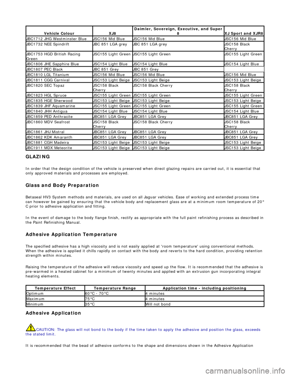
Vehicle ColourXJ8Daimler, Sovereign, Executive, and Super
8XJ Sport and XJR8
JBC1712 JHG Westminster BlueJSC156 Mid BlueJSC156 Mid BlueJSC156 Mid Blue
JBC1732 NEE SpindriftJBC 851 LGA greyJBC 851 LGA greyJSC158 Black
Cherry
JBC1753 HGD British Racing
GreenJSC155 Light GreenJSC155 Light GreenJSC155 Light Green
JBC1806 JHE Sapphire BlueJSC154 Light BlueJSC154 Light BlueJSC154 Light Blue
JBC1807 PEC BlackJBC 851 GreyJBC 851 Grey
JBC1810 LGL TitaniumJSC156 Mid BlueJSC156 Mid BlueJSC156 Mid Blue
JBC1811 CGG CarnivalJSC153 Light BeigeJSC153 Light BeigeJSC153 Light Beige
JBC1820 SEC TopazJSC158 Black
CherryJSC158 Black CherryJSC158 Black
Cherry
JBC1823 HGL SpruceJSC155 Light GreenJSC155 Light GreenJSC155 Light Green
JBC1835 HGE SherwoodJSC153 Light BeigeJSC153 Light BeigeJSC153 Light Beige
JBC1839 JHF AquamarineJSC155 Light GreenJSC155 Light GreenJSC155 Light Green
JBC1840 JHH AntiguaJSC154 Light BlueJSC154 Light BlueJSC154 Light Blue
JBC1859 PED AnthraciteJBC851 LGA GreyJBC851 LGA GreyJBC851 LGA Grey
JBC1860 MDV SeafrostJSC158 Black
CherryJSC158 Black CherryJSC158 Black
Cherry
JBC1861 JHJ MistralJBC851 LGA GreyJBC851 LGA GreyJBC851 LGA Grey
JBC1862 KDK AmaranthJBC851 LGA GreyJBC851 LGA GreyJBC851 LGA Grey
JBC1881 CGH MadeiraJSC153 Light BeigeJSC153 Light BeigeJSC153 Light Beige
JBC1911 MDX MeteoriteJSC153 Light BeigeJSC153 Light BeigeJSC153 Light Beige
Temperature EffectTemperature RangeApplication time - including positioning
Optimum60°C - 70°C4 minutes
Maximum75°C4 minutes
Minimum35°CWill not bond
Page 2422 of 2490
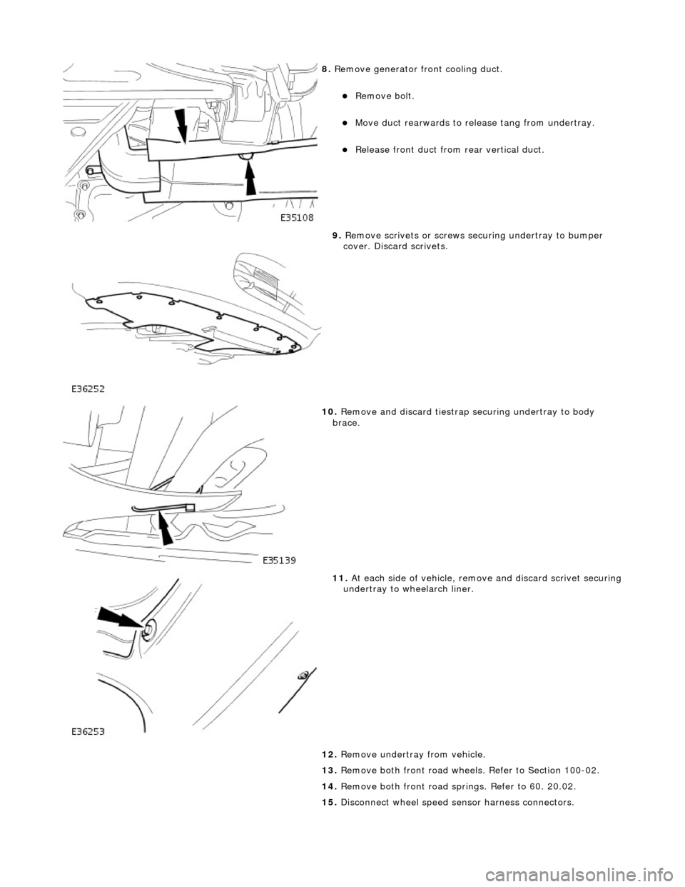
8. Remove generator front cooling duct.
Remove bolt.
Move duct rearwards to rele ase tang from undertray.
Release front duct from rear vertical duct.
9. Remove scrivets or screws se curing undertray to bumper
cover. Discard scrivets.
10. Remove and discard tiestrap securing undertray to body
brace.
11. At each side of vehicle, remo ve and discard scrivet securing undertray to wheelarch liner.
12. Remove undertray from vehicle.
13. Remove both front road wheels. Refer to Section 100-02.
14. Remove both front road springs. Refer to 60. 20.02.
15. Disconnect wheel speed sensor harness connectors.
Page 2423 of 2490
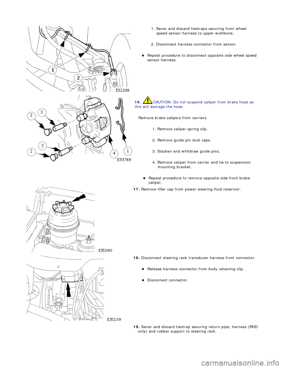
1. Sever and discard tiestraps securing front wheel
speed sensor harness to upper wishbone.
2. Disconnect harness connector from sensor.
Repeat procedure to disconnect opposite side wheel speed
sensor harness.
16. CAUTION: Do not suspend caliper from brake hose as
this will damage the hose.
Remove brake calipers from carriers.
1. Remove caliper spring clip.
2. Remove guide pin dust caps.
3. Slacken and withdraw guide pins.
4. Remove caliper from carrier and tie to suspension mounting bracket.
Repeat procedure to remove opposite side front brake
caliper.
17. Remove filler cap from power steering fluid reservoir.
18. Disconnect steering rack transducer harness front connector.
Release harness connector from body retaining clip.
Disconnect connector.
19. Sever and discard tiestrap secu ring return pipe, harness (RHD
only) and rubber support to steering rack.
Page 2436 of 2490
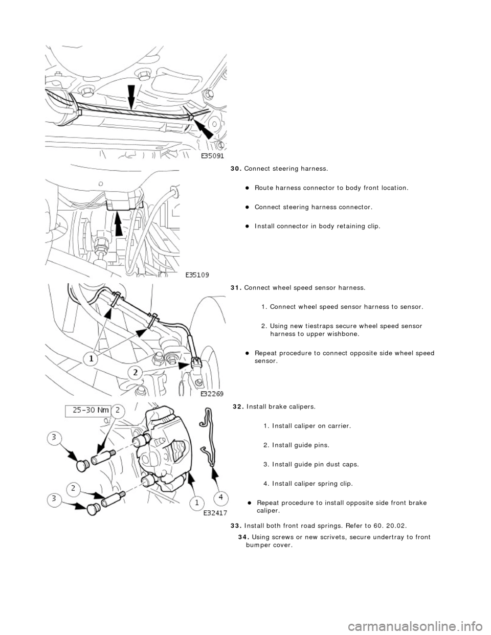
30. Connect steering harness.
Route harness connector to body front location.
Connect steering ha rness connector.
Install connector in body retaining clip.
31. Connect wheel speed sensor harness.
1. Connect wheel speed sensor harness to sensor.
2. Using new tiestraps secure wheel speed sensor harness to upper wishbone.
Repeat procedure to connect opposite side wheel speed
sensor.
32. Install brake calipers.
1. Install caliper on carrier.
2. Install guide pins.
3. Install guide pin dust caps.
4. Install caliper spring clip.
Repeat procedure to install opposite side front brake
caliper.
33. Install both front road sp rings. Refer to 60. 20.02.
34. Using screws or new scrivets , secure undertray to front
bumper cover.