1998 JAGUAR X308 check engine
[x] Cancel search: check enginePage 1600 of 2490
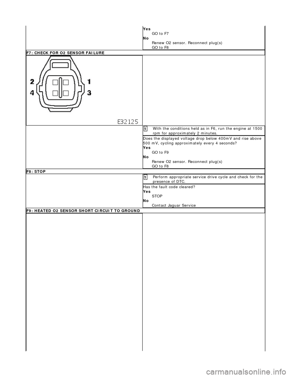
Yes GO to F7
No Renew O2 sensor. Reconnect plug(s)
GO to F8
F7: CHECK FOR O2 SENSOR FAILURE
With the conditions held as in F6, run the engine at 1500
rpm for approximately 2 minutes. 1
Does the displayed voltage drop below 400mV and rise above
500 mV, cycling approximately every 4 seconds?
Yes GO to F9
No Renew O2 sensor. Reconnect plug(s)
GO to F8
F8: STOP
Perform appropriate service drive cycle and check for the
presence of DTC. 1
Has the fault code cleared?
Yes STOP
No Contact Jaguar Service
F9: HEATED O2 SENSOR SHORT CIRCUIT TO GROUND
Page 1610 of 2490
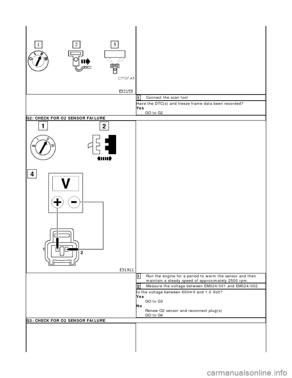
Connect the scan tool 1
Have the DTC(s) and freeze frame data been recorded?
Yes GO to G2
G2: CHECK FOR O2 SENSOR FAILURE
Run the engine for a period to warm the sensor and then
maintain a steady speed of approximately 2500 rpm. 1
Measure the voltage between EM024/001 and EM024/002. 2
Is the voltage between 600mV and 1.0 Volt?
Yes
GO to G3
No Renew O2 sensor and reconnect plug(s)
GO to G6
G3: CHECK FOR O2 SENSOR FAILURE
Page 1613 of 2490
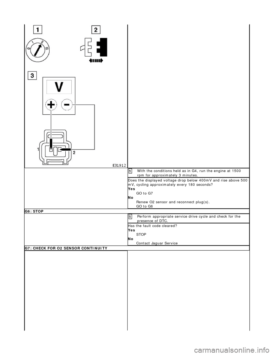
With the conditions held as in G4, run the engine at 1500
rpm for approximately 3 minutes. 1
Does the displayed voltage drop below 400mV and rise above 500
mV, cycling approximately every 180 seconds?
Yes GO to G7
No Renew O2 sensor and reconnect plug(s).
GO to G6
G6: STOP
Perform appropriate service drive cycle and check for the
presence of DTC. 1
Has the fault code cleared?
Yes STOP
No Contact Jaguar Service
G7: CHECK FOR O2 SENSOR CONTINUITY
Page 1625 of 2490
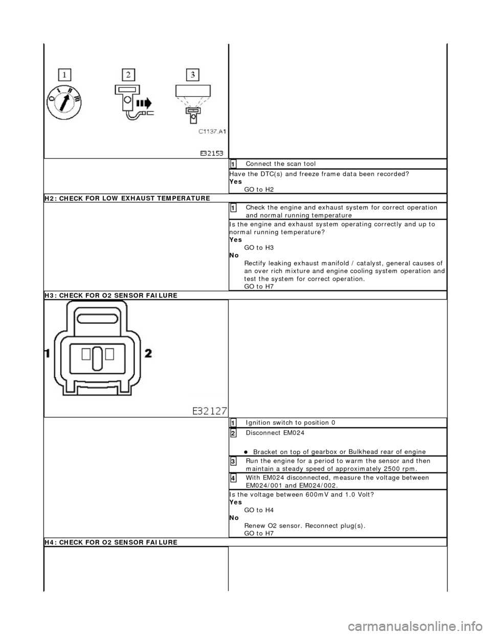
Conne
ct the scan tool
1
Have the DTC(s) and fr
eeze
frame data been recorded?
Yes GO to H2
H2: CHECK
FOR LOW EXHAUST TEMPERATURE
Chec
k the engine and exhaust
system for correct operation
and normal running temperature
1
Is th
e engine and exhaust system operating correctly and up to
normal running temperature?
Yes GO to H3
No Rectify leaking exhaust manifold / catalyst, general causes of
an over rich mixture and engine cooling system operation and
test the system for correct operation.
GO to H7
H
3: CHECK FOR O2 SENSOR FAILURE
I
gnition switch to position 0
1
Di
sconnect EM024
Bracket on top o
f gearbox or
Bulkhead rear of engine
2
R
un the engine for a period to
warm the sensor and then
maintain a steady speed of approximately 2500 rpm.
3
W
ith EM024 disconnected, measure the voltage between
EM024/001 and EM024/002.
4
Is
the voltage between 600mV and 1.0 Volt?
Yes GO to H4
No Renew O2 sensor. Reconnect plug(s).
GO to H7
H
4: CHECK FOR O2 SENSOR FAILURE
Page 1626 of 2490
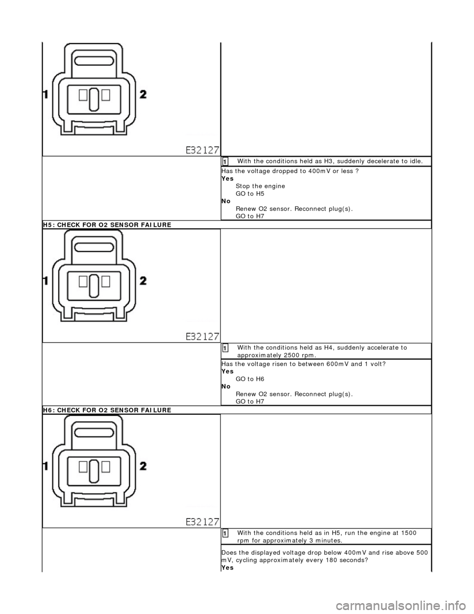
With
the conditions held as H3, suddenly decelerate to idle.
1
Has the voltage
d
ropped to 400mV or less ?
Yes Stop the engine
GO to H5
No Renew O2 sensor. Reconnect plug(s).
GO to H7
H5
: CHECK FOR O2 SENSOR FAILURE
Wi
th
the conditions held as H4, suddenly accelerate to
approximately 2500 rpm.
1
Has the
voltage risen to between 600mV and 1 volt?
Yes GO to H6
No Renew O2 sensor. Reconnect plug(s).
GO to H7
H6
: CHECK FOR O2 SENSOR FAILURE
W
i
th the conditions held as in H5, run the engine at 1500
rpm for approximately 3 minutes.
1
Does th e displayed voltage drop below 40
0mV and rise above 500
mV, cycling approximately every 180 seconds?
Yes
Page 1689 of 2490
Fuel System - General Information - Fuel System Pre
ssure Check
Gen
eral Procedures
WARNING: Working on the fuel system re sults in fuel and fuel vapor being present in the atmosphere. Fuel vapor is
extremely flammable, hence great care must be taken whilst working on the fuel system. Adhere strictly to the following
precautions:
D
o not smoke in the work area
Di
splay
NO SMOKING signs around the work area
D
isconnect the battery before
working on the fuel system
Av
oid sparks
Make sure sui
table fire ex
tinguishers are at hand
Make sure absor
bent material is at
hand to soak up any spillage
Make sure the work area is
well ventilated
M
ake sure that the gauge is correctly conn
ected, and that all connections are secure BEFORE starting the engine
DO N
OT
disconnect the gauge from the schrader valve while the engine is running
Make su
re the schrader valve reseals once the gauge is disconnected
• NOTE: Depending on the design of the ga uge set, there may be a drain valve and tube. Make sure this valve is closed, and
the drain tube placed in a suitable container BEFORE connecting the gauge to the schrader valve.
1. Make sure the vehi
cle is in
Park for vehicles with automatic
transmission, Neutral for vehicles with manual transmission.
2. Apply the parking brake.
3. Place suitable absorbent material around the schrader valve to
absorb any spillage when connecting the gauge set.
4. Remove the protective cap from the schrader valve.
5. Connect the gauge, using adaptors if required.
6. Remove the absorbent material and dispose of safely.
7. Disconnect and plug the vacuum hose from the pressure
regulator.
8. Start the engine and record the fuel pressure reading.
As a gui
de, the fuel pressu
re should be approximately 3.0
bar (44.1 psi) with the regulator disconnected.
9. With the engine still running, reconnect the vacuum hose to
the pressure regulator an d record the reading.
Th
e pressure should dr
op to approximately 2.6 bar (38
psi) when the vacuum hose is reconnected.
10. Switch off the engine.
11. Place more absorbent material around the schrader valve.
12. Where fitted, open the drain valve and allow the fuel from the
gauge and line to flow into the container to depressurize the
system.
13. Disconnect and remove the gauge set and any adaptors.
14. Clean up any fuel which may have been spilt and remove the
absorbent material. Dispose of safely.
15. Refit and secure the protective cap to the schrader valve.
16. Reconnect the fuel pressure regulator vacuum hose.
17. Start the engine and make sure there are no leaks.
Page 1743 of 2490
Accelerati
on Control - Accelerator Cable Adjustment
Gen
eral Procedures
1.
Load the Approved Jaguar Diagno stic System with power train
data logger.
2. Connect the Approved Jaguar Diag nostic System to the vehicle.
3. W
ith 'Disable Network Integrity Test - YES/ NO' displayed on
the screen select YES.
4. With new menu displayed on the screen, select ' Engine
Management'.
5. Turn the ignition to ON.
R
emove any previously selected data logger parameters.
6. On data logger select PPS11 an d PPS2 (Pedal demand sensors
1 and 2).
7. On Sedan models only, remove the bulkhead covers on both
sides and the engine compartment rear cover.
8. Cut, remove and discard the ra tchet strap which retains the
throttle cable to the abutment bracket.
9. Ensure there is no tension on the throttle cable by releasing
the throttle cable adjustment nut from the abutment bracket.
10. Record the voltages for both sensors, PPS11 and PPS2.
11. Partially insert the throttle cable adjustment nut into the
abutment bracket.
12. Recheck the voltages for both sensors, PPS11 and PPS2.
13. Where the voltages at step 12 are higher than the voltages
taken at step 10, contin ue to step 15 below.
14. Where the voltages at step 12 are the same as the voltages
taken at step 10, contin ue to step 16 below.
15. Rotate the adjustment nut clockwise (as viewed from the
front of the vehicle) until the same voltages are indicated as in
step 10. Continue to turn thro ugh a part revolution until the
sides of the nut are vertical. Tu rn through a further 90 degrees,
then fully insert the nut into the abutment bracket.
16. Rotate the adjustment nut anti-clockwise (as viewed from the
front of the vehicle) until the indicated voltage starts to
increase. Then rotate the nut clockwise through a part
revolution until the sides are ve rtical. Turn through a further 90
degrees, then fully insert the nut into the abutment bracket.
17. Fit a new ratchet strap to secure the throttle cable adjusting
nut to the abutment bracket.
18. Operate the throttle pedal through 20 full cycles to settle the
cable. Check the voltages now shown, remain the same as in
steps 15 and 16.
19. Check and where necessary adjust the kickdown switch. For
additional information, refer to Section 307
-05A Automatic Transmissi
on/Transaxle External Controls
Sectio
n
307
-05
B
Au
tomatic Transmission/Tra
nsaxle External Controls
.
20
.
On Sedan models only, refit the engine compartment rear
cover and the bulkhead co vers on both sides.
21. Switch the ignition OFF and disconnect the Approved Jaguar
Diagnostic System.
Page 1756 of 2490
Probable
causes of faults may be found by comparing actual
system pressures, registered on your manifold gauge set or
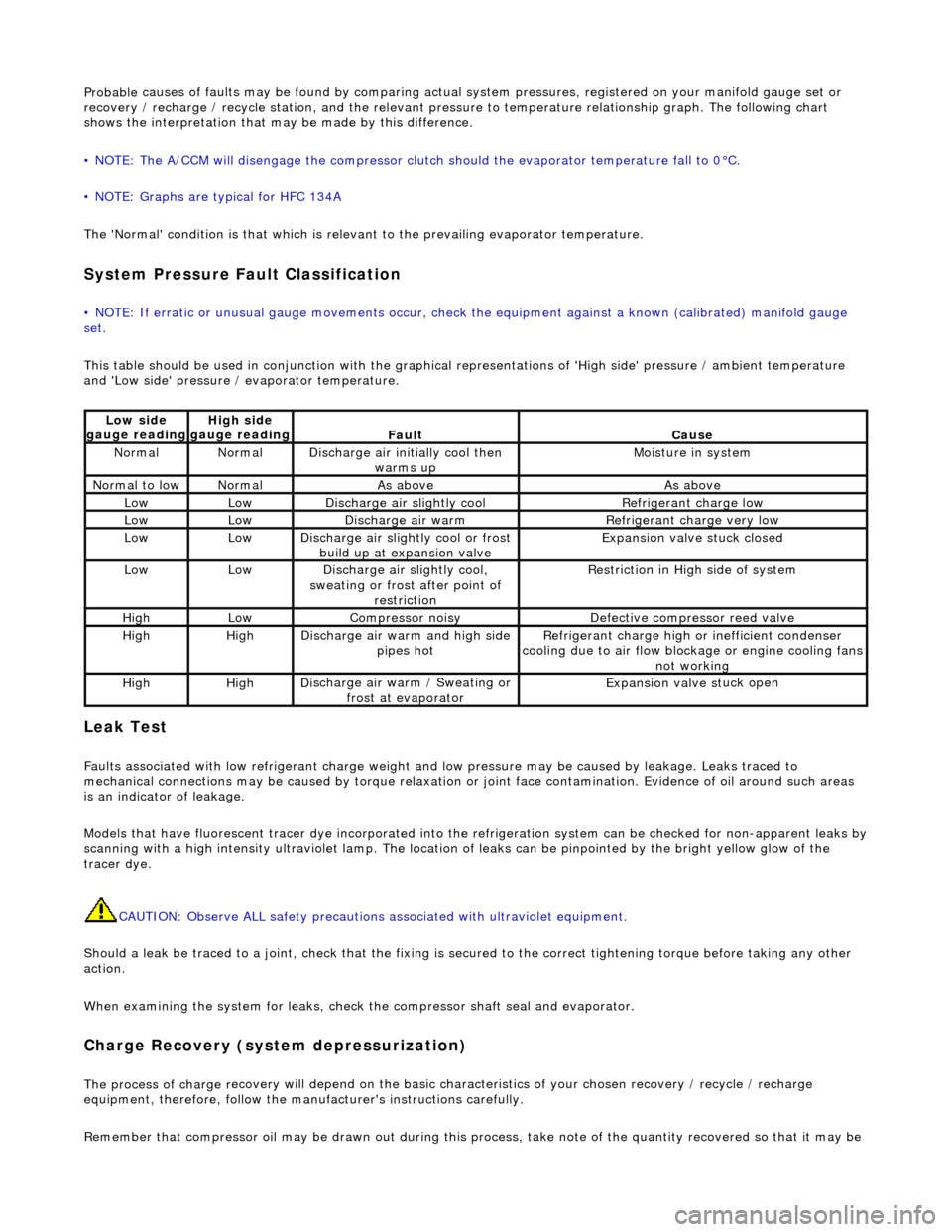
recovery / recharge / recycle station, and the relevant pressure to temperature relationship graph. The following chart
shows the interpretation that ma y be made by this difference.
• NOTE: The A/CCM will disengage the compressor clutch should the evaporator temperature fall to 0°C.
• NOTE: Graphs are typical for HFC 134A
The 'Normal' condition is that which is relevant to the prevailing evaporator temperature.
System Pressure Fault Classification
• NOTE
: If erratic or unusual gauge move
ments occur, check the equipment against a known (calibrated) manifold gauge
set.
This table should be used in conjunction with the graphical representations of 'High side' pressure / ambient temperature
and 'Low side' pressure / evaporator temperature.
Leak
Test
F
a
ults associated with low re
frigerant charge weight and low pressure ma y be caused by leakage. Leaks traced to
mechanical connections may be caused by to rque relaxation or joint face contamination. Evidence of oil around such areas
is an indicator of leakage.
Models that have fluorescent tracer dye incorporated into the refrigeration system can be checke d for non-apparent leaks by
scanning with a high intensity ultraviolet lamp. The location of leaks can be pinpointed by the bright yellow glow of the
tracer dye.
CAUTION: Observe ALL safety precautions associated with ultraviolet equipment.
Should a leak be traced to a joint, check that the fixing is secured to the correct tightening torque before taking any other
action.
When examining the system for leaks, chec k the compressor shaft seal and evaporator.
Charge Re
covery (system depressurization)
The process of
charge r
ecovery will depe
nd on the basic characteristics of your chosen recovery / recycle / recharge
equipment, therefore, follow the manu facturer's instructions carefully.
Remember that compressor oil may be drawn out during this process, take note of the quantity recovered so that it may be
Lo
w side
gauge reading
High s i
de
gauge reading
Fau l
t
Cause
No
r
mal
No
r
mal
Di
sc
harge air initially cool then
warms up
Mois
ture in system
N
ormal
to low
No
r
mal
As aboveAs above
LowLowD
i
scharge air slightly cool
Ref
r
igerant charge low
LowLowDi
scharge air warm
Refr
igerant charge very low
LowLowDi
scharge air slightly cool or frost
build up at expansion valve
Expansion valve st
uck closed
LowLowDi
scharge air slightly cool,
sweating or frost after point of restriction
Restri
ction in High side of system
HighLowCompressor noisyDe
fe
ctive compressor reed valve
HighHighD
i
scharge air warm and high side
pipes hot
Refri
gerant charge high or inefficient condenser
cooling due to air flow blockage or engine cooling fans
not working
HighHighD i
scharge air warm / Sweating or
frost at evaporator
Expans ion valve st
uck open