1998 JAGUAR X308 torque
[x] Cancel search: torquePage 48 of 2490

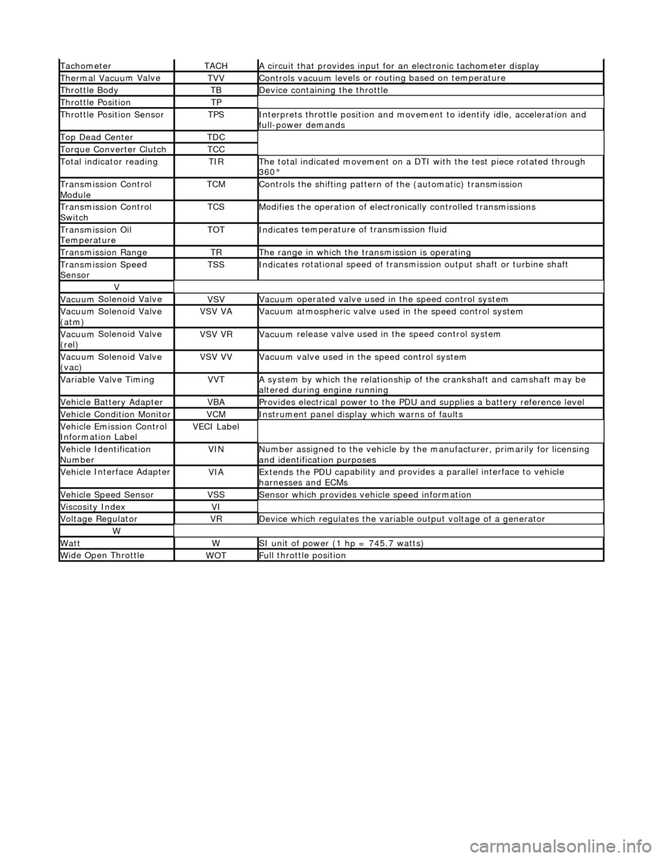
Tacho
meter
TACHA
ci
rcuit that provides input for
an electronic tachometer display
Thermal Vacuu
m Valve
TVVControls vacuum l
e
vels or
routing based on temperature
Throttle
Body
TBDe
vi
ce containing the throttle
Throttl
e
Position
TP
Throttl
e
Position Sensor
TPSInterprets throttl
e
position and movement to iden tify idle, acceleration and
full-power demands
Top Dead CenterTDC
Torque Converter C
lutch
TCC
To
tal
indicator reading
TIRThe t
o
tal indicated movement on a DTI with the test piece rotated through
360°
Transm
ission Control
Module
TCMControls
the shifting pattern
of the (automatic) transmission
Transm
ission Control
Switch
TCSModifi es
the operation of electronically controlled transmissions
Transmission Oil
TemperatureTOTIndi
cat
es temperature of transmission fluid
Transmission RangeTRThe ran
g
e in which the transmission is operating
Transmission Spe
e
d
Sensor
TSSIndi cat
es rotational speed of transmission output shaft or turbine shaft
V
Vacuu
m
Solenoid Valve
VSVVacuu
m
operated valve used in the speed control system
Vacuu
m
Solenoid Valve
(atm)
VSV VAVacuu m
atmospheric valve used in the speed control system
Vacuu
m
Solenoid Valve
(rel)
VSV VRVacuu m
release valve used in the speed control system
Vacuu
m
Solenoid Valve
(vac)
VSV VVVacuu m
valve used in the speed control system
Variable Valve TimingVVTA
s
ystem by which the relationship of the crankshaft and camshaft may be
altered during engine running
Vehi cl
e Battery Adapter
VBAProvide
s
electrical power to the PDU
and supplies a battery reference level
Vehicl
e Condition Monitor
VCMInst
rum
ent panel display which warns of faults
Ve
hic
le Emission Control
Information Label
VECI Label
Vehi cl
e Identification
Number
VINN u
mber assigned to the vehicle by the manufacturer, primarily for licensing
and identification purposes
Vehi cl
e Interface Adapter
VIAExtends the
PDU ca
pability and provid
es a parallel interface to vehicle
harnesses and ECMs
Vehicle Spe e
d Sensor
VSSSens
or which provides ve
hicle speed information
Viscosity In
dexVI
Voltage RegulatorVRDe
vice which regulates the variable output voltage of a generator
W
Wat
tWSI unit of power (1 hp = 7
45.7 watts)
W
i
de Open Throttle
WO
TFu
ll throttle position
Page 67 of 2490

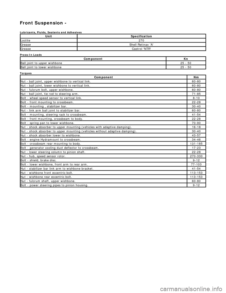
Front Suspension -
Lubri
cants, Fluids, Sealants and Adhesives
Press-In Loads
Torques
UnitS
pecification
Loctite27
0
Greas
e
Shell Retin
ax 'A'
Greas
e
Castro
l 'NTR'
Com
ponent
Kn
Ball join
t to upper wishbone
25
- 50
B
all joint to lower wishbone
25
- 50
Com
ponent
Nm
N
ut - ball joint, upper wishbone to vertical link.
60
-80
N
ut - ball joint, lower wishbone to vertical link.
60
-80
Nu
t - fulcrum bolt, upper wishbone.
60
-80
N
ut - ball joint, tie rod to steering arm.
71
-85
Bol
t - wheel speed sensor to vertical link.
8-1
0
Bol
t - front mounting to crossbeam.
22
-28
Bolt
- mounting , stabilizer bar.
30
-40
N
ut - link arm ball joint to stabilizer bar.
60
-80
Bolt
- mounting, steering rack to crossbeam.
41
-54
B
olt - front mounting, crossbeam to body.
22
-28
Bol
t - spring pan to lower wishbone.
70
-90
N
ut - shock absorber to upper mounting
(vehicles with adaptive damping).
16
-18
Nu
t - shock absorber to upper mounting (vehicles without adaptive damping).
30
-40
N
ut - shock absorber lower to wishbone.
43
-57
B
olt - engine Hydramount to crossbeam.
34
-46
B
olt - crossbeam rear mounting to body.
13
1-185
Bol
t - generator cooling du
ct deflector to crossbeam.
17
-23
N
ut - lower steering column to pinion shaft.
22
-28
N
ut - hub, speed sensor rotor.
27
0-330
B
olt - shield, brake disc.
9-1
2
Bol
t - lower wishbone, front arm to rear arm.
77
-103
Nu
t - stabilizer bar link arm to wishbone bracket.
41
-54
N
ut - wishbone front
eccentric bolt.
11
3-153
Nu
t - wishbone rear
eccentric bolt.
11
3-153
N
ut - fulcrum shaft, upper wishbone.
60
-80
Bolt -
power steering pi
pes to pinion housing.
9-1
2
Page 166 of 2490

Rear Su
spension -
Lubric
ants, Fluids, Sealants and Adhesives
Torques
UnitSp
ecification
Loctite27
0
Greas eShell Retin a
x 'A'
Greas
eCastro l 'NT
R'
Com
p
onent
Nm
N
u
t - hub to axle shaft
3
04 -
336
Nu
t -
hub carrier pivot pin
88
-
118
Bol
t
- ABS sensor to hub carrier
8-1
0
Nu
t - stabilizer bar link to lower wishbone.
30
-40
Nu
t - stabilizer bar to link assembly.
30
-40
Bolts -
monostrut to body mounting brackets
88
-
118
Bolt
s
- monostrut to wishbone tie assembly
77
-
103
Bolts
- bu
mp stop to body
26
-34
Bol t
- damper lower mounting
80
-
100
N
u
t - damper top
31
-39
Bolts -
damper mounting plate to body
17
-23
Page 266 of 2490

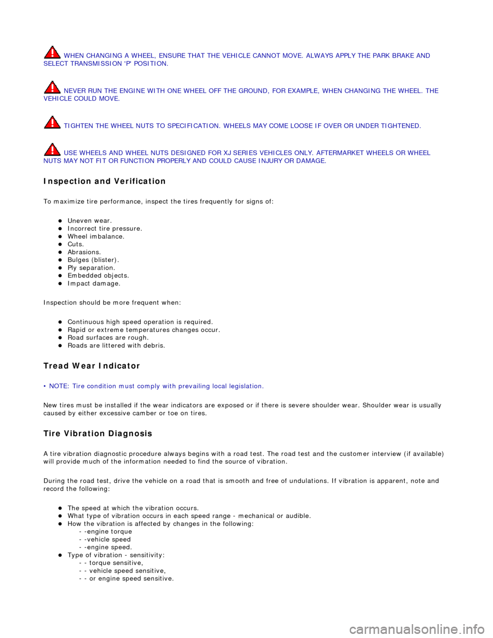
WHE
N CHANGING A WHEEL, ENSURE THAT THE VEHICLE CANNOT MOVE. ALWAYS APPLY THE PARK BRAKE AND
SELECT TRANSMISSION 'P' POSITION.
NEVER RUN THE ENGINE WITH ONE WHEEL OFF THE GROUND, FOR EXAMPLE, WHEN CHANGING THE WHEEL. THE
VEHICLE COULD MOVE.
TIGHTEN THE WHEEL NUTS TO SPECIFICATION. WHEELS MAY COME LOOSE IF OVER OR UNDER TIGHTENED.
USE WHEELS AND WHEEL NUTS DESI GNED FOR XJ SERIES VEHICLES ONLY. AFTERMARKET WHEELS OR WHEEL
NUTS MAY NOT FIT OR FUNCTION PROPERLY AND COULD CAUSE INJURY OR DAMAGE.
In
spection and Verification
To maximize ti
re performance, inspec
t the tires frequently for signs of:
Unev
en wear.
Incorrect
ti
re pressure.
Wh
ee
l imbalance.
Cuts. Abrasi
ons.
B
u
lges (blister).
Ply s
e
paration.
Embedded objects. Impact damage.
Inspe c
tion should be
more frequent when:
Continuo
us high speed op
eration is required.
Ra
pid or extreme temperatures changes occur.
R
o
ad surfaces are rough.
Roads ar
e littered
with debris.
Tread W
e
ar Indicator
•
NO
TE: Tire condition must comply with prevailing local legislation.
New tires must be installed if the wear in dicators are exposed or if there is severe shoulder wear. Shoulder wear is usually
caused by either excessive camber or toe on tires.
T i
re Vibration Diagnosis
A
tir
e vibration diagnostic procedure always
begins with a road test. The road test and the custom er interview (if available)
will provide much of the information need ed to find the source of vibration.
During the road test, drive the vehicle on a road that is smooth and free of undulations. If vibration is apparent, note and
record the following:
The s p
eed at which the vibration occurs.
W
h
at type of vibration occurs in each
speed range - mechanical or audible.
How the vibrati
on is affected
by changes in the following:
- -engine torque
- -vehicle speed
- -engine speed.
Type of v i
bration - sensitivity:
- - torque sensitive,
- - vehicle speed sensitive,
- - or engine speed sensitive.
Page 267 of 2490

The
following explanations will help isolate the source of vibration.
Torque Sensitive
This
means that the condition can be impr
oved or made worse by accelerating, dece lerating, coasting, maintaining a steady
vehicle speed, or applying engine torque.
Ve
hicle Speed Sensitive
This means th
at the vibration al
ways occurs at the same vehicle speed and is not affected by engine torque, engine speed
or gear selection.
Engine Speed Sensit
ive
This means th
at the vibration
occurs at varying vehicle spee ds when a different gear is selected. It can sometimes be
isolated by increasing or decreasing engine speed with the tran smission in neutral or by stall testing with the transmission in
gear. If the condition is engine speed sensitive, the cause is probably not related to tires.
If the road test indicates that there is tire wine, but no shake or vibration, the noise originates with the contact between th e
tire and the road surface.
A thumping noise usually means that the tire is flat or has soft spots making a noise as they slap the roadway. Tire whine
can be distinguished from axle no ise, as tire whine remains the same over a range of speeds.
Sym
ptom Chart
Sy
mptom Chart
Sy
mptom
Possib
le Sources
Acti
on
Uneven ti
re wear.
Incorrect ti
re inflation.
*
Cor
rect to specification.
*
Exce
ssive radial an
d lateral runout.
*
Renew tire
or wheel.
*
O
ut of specification steering
geometry.
*
R
ealign steering geometry: Refer to Section 204-
00.
*
W
orn ball joint.
*
Renew
damaged component, realign steering
geometry.
*
W
orn tie-rod end.
*
R
enew component, realign steering geometry.
*
Incorrect
tire / wheel usage.
*
Inst
all correct tire and wheel combination.
*
Loose or leaki
ng shock absorbers.
*
Tigh
ten or Renew as nece
ssary: Refer to Section
204-00.
*
Suspensi
on geometry out of
alignment.
*
Che
ck and adjust: Refer to Section 204-00.
*
Loose, worn or da mage
d suspension
components.
*
In
spect, Repair or Renew as necessary.
*
Wh
eel and tire assembly out of
balance.
*
Balance wheel an
d tire assembly.
*
Excessive later
al or radial runout of
wheel or tire.
*
Check, Repair o
r
Renew as required.
*
Tire
s show excess wear on
edge of treads.
Ti
res under-inflated.
*
Cor
rect pressure to specification.
*
Vehi
cle overloaded.
*
Cor
rect to specification.
*
Tire
s show excess wear on
edge of treads (with tire
pressures correct).
Incorre
ct toe setting.
*
Se
t to specification: Refer to Section 204-00.
*
Tire
s show excess wear in
center of tread.
Tire
s over-inflated.
*
Cor
rect pressure to specification
*
W
heel mounting is
difficult.
Incorrect app
lication or mismatched
parts, including wheel studs and
wheel nuts. Corroded, worn or
damaged parts.
*
Fol
low the manufacturer's specifications. Clean or
Renew.
*
Wobble or sh
immy
affecting wheel runout.
Damaged wh
eel (eventually
damaging wheel bearings and causing
uneven tire wear).
*
Inspect wheel rims for
damage and runout. Renew
as required.
*
Vehicle vibrations from
Tire
s / wheels mismatched.
*
Inst
all correct tire / wheel combination.
*
Page 268 of 2490

wheels
and tires.
Infl
atio
n pressure too high or low.
*
Cor r
ect pressure to specification
*
Uneven ti re wear.
*Re fe
r to Diagnosis and Testing in this section.
*
Wh ee
l and tire assembly imbalance.
*
Balance wheel an d tire assembly.
*
Brake disc imbalan c
e.
*
Check brak e disc co
oling fins for mud and foreign
material. Check for damage or disc heavy spot.
Refer to Section 206-00.
*
Damaged or distor
ted wh
eel.
*
Renew wh eel.
*
Excessive radial run-o
ut of wheel or
tire. Excessive lateral run-out of wheel or
tire.
*
*
Renew wh
eel or tire.
*
Incorrectl y
seated tire.
*
R e
mount the tire.
*
Loose wh eel mo
untings: damaged
wheel studs, whee l nuts, worn or
broken wheel hub face or foreign
material on mounting faces.
*
Tigh
te
n or Renew worn or
damaged parts. Clean
mounting surfaces.
*
De
fe
ctive wheel bearings.
*
Renew worn
or damaged bearing sets: Refer to
Section 204-00.
*
W
a
ter in tires.
*
R e
move water.
*
Damaged wh eel stud
thre
ads.
Sli
d
ing wheel across the wheel studs
during installation. Loose wheel nuts.
*
Renew wh
eel studs.
*
Broken wh eel
studs.
Loose or overti
ght
ened wheel nuts.
*
Renew wh eel studs.
*
C o
rrosion / contamination
streaks from wheel stud
holes.
Loose wh eel
nuts.
*
Chec k com
plete assembly. Renew damaged parts.
Apply correct torque setting.
*
Damaged wh
eel nu
ts.
Loose wh
eel
assembly.
Over-tightened wheel nuts.
*
*
Renew wh
eel nu
ts. Apply correct torque setting.
*
Se ize
d wheel nuts.
Cor
rosion
*
CAUTI O
N: Do not permit lubricant to
contaminate wheel hub stud holes or wheel nut seats.
If corrosion is light, wire brush away corrosion. If
corrosion is excessive renew wheel studs and wheel
nuts. Lubricate th e first three threads of wheel
studs with a graphite based lubricant.
*
Page 280 of 2490

Driveshaft -
Torques
Comp
onent
Nm
Bol
t
M12 - Jurid flexible coupling to
transmission and final drive flanges
75
-
88
Screw
-
Centre bearing to underbody
19
,5
- 26,5
Screw
-
Parking brake relay mounting bracket to underbody
19
,5
- 26,5_
Page 284 of 2490

Re
ar Drive Axle/Differential -
Lubric
ants, Fluids, Sealants and Adhesives
Capacities
Torques
UnitSp
ecification
F
i
nal Drive
Shell Sp
irax Supe
r TS 90
Hub s
p
line to Axle shaft
Loct
it
e 270 Studlock or equivalent
UnitLi
t
ers
F
i
nal Drive
1,
90
Com p
onent
Nm
B
ol
t - Final drive nose plate
39
- 51
Bol t
- 'A' frame to final drive
9
0 -
110
Nu
t 'A' f
rame to rear mounting bracket
8
5 -
115
Nu
t -
Axle shaft to final drive flange
81
-
99
Nu
t -
Axle shaft to hub
3
04 -
336
N
u
t - Damper lower fixing
8
0 -
100
Bol
t
M12 - Jurid flexible coupling to
transmission and final drive flanges
75 -
88
N
u
t - Lower fulcrum
9
0 -
110
Nu
t -
Pendulum to final drive
1
60 -
200
N
u
t - Stabilizer to wishbone
30
-
40
N
u
t - Tie rod to final drive
8
5 -
105
Nu
t -
Tie rod to wide mounting bracket
8
5 -
115
Nu
t -
Wishbone pivot
8
0 -
100
N
u
t - Wishbone tie to final drive
8
5 -
105
N
u
t 'A' frame to wide mounting bracket
8
5 -
105