1998 JAGUAR X308 engine oil
[x] Cancel search: engine oilPage 929 of 2490

The cooling
pack incorporates the radiator a
ssembly with integral transmission oil cool er (located in the radiator outlet tank),
an air conditioning condenser, and the cooling fans and cowl assembly.
The cooling pack on supercharged vehicles is the same as described above, but with the addition of a charge air cooler
coolant radiator located in front of the condenser.
Radiator Mounti
ng/Retention
T
he radiator is mounted on four rubber mounts, one on each
end of the upper and lower horizontal face. The two lower
mountings are supported on two isolated brackets mounted on the body; the lower cradle assembly has subsequently been
deleted.
A closing panel made from polypropylene, which retains the radiat or assembly, fits over the top of the radiator and is bolted
to the vehicle top panel.
Coolant Hoses - Engine
Page 935 of 2490
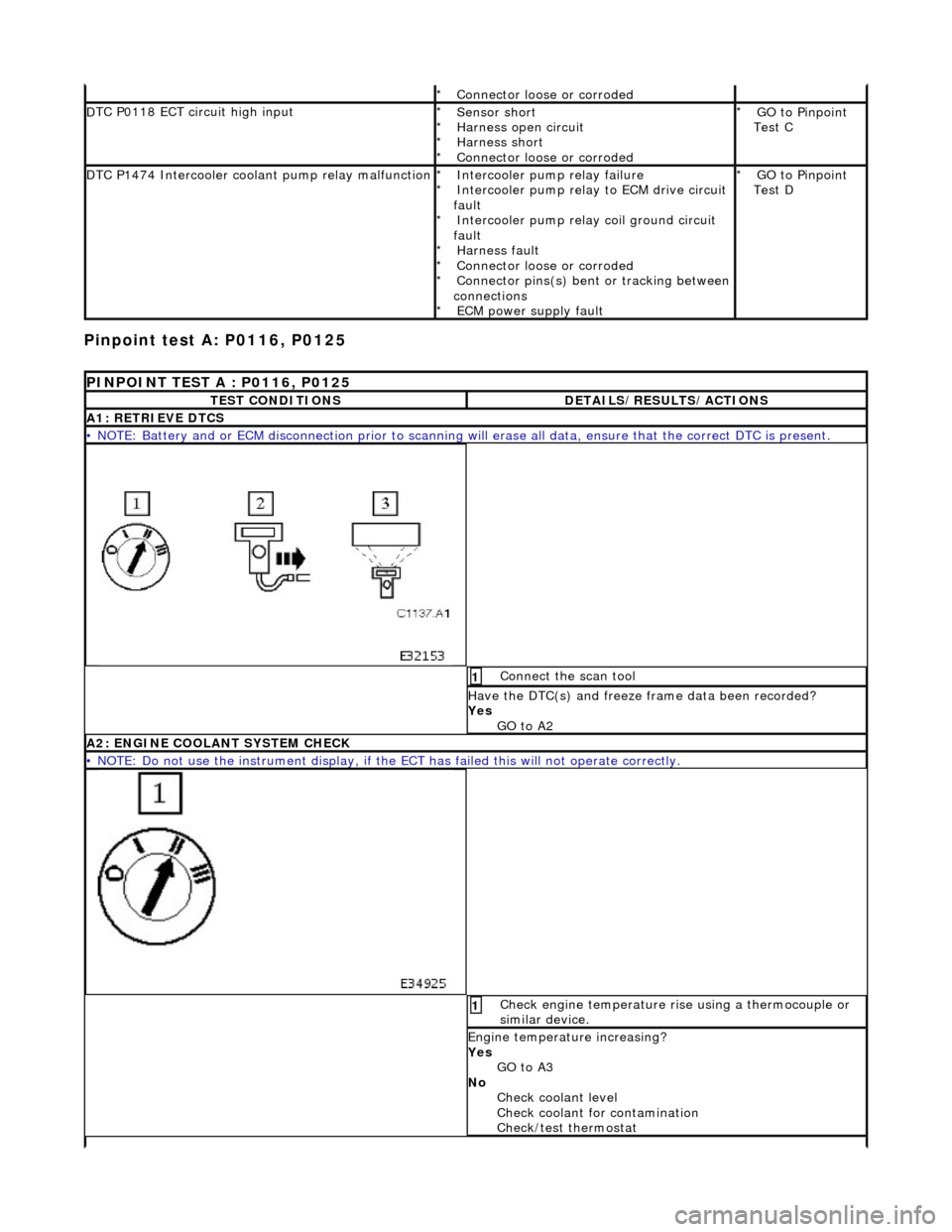
Pinpoint test
A: P0116, P0125
Connector
loose or corroded
*
D
TC P0118 ECT circuit high input
Sensor short
Harness open circui
t
Harness short
Connector loose or corroded
*
*
*
*
GO to Pinpoint
Test C
*
D
TC P1474 Intercooler coolant pump relay malfunction
Intercooler pump relay
failure
Intercooler pump relay to ECM drive circuit
fault Intercooler pump relay coil ground circuit
fault Harness fault
Connector loose or corroded
Connector pins(s) bent or tracking between
connections ECM power supply fault
*
*
*
*
*
*
*
GO to Pinpoint
Test D
*
P
INPOINT TEST A : P0116, P0125
T
EST CONDITIONS
D
ETAILS/RESULTS/ACTIONS
A1
: RETRIEVE DTCS
•
NOTE: Battery and or ECM disconnection prior to scanning wi
ll erase all data, ensure that the correct DTC is present.
Conne
ct the scan tool
1
Have the DTC(s) and fr
eeze
frame data been recorded?
Yes GO to A2
A2: ENGINE
COOLANT SYSTEM CHECK
•
NOTE: Do not use the instrument display, if th
e ECT has failed this will not operate correctly.
Chec
k engine temperature rise using a thermocouple or
similar device.
1
Engine
temperature increasing?
Yes GO to A3
No Check coolant level
Check coolant for contamination
Check/test thermostat
Page 973 of 2490

Engine Cooling - Radiator4.0L NA V8 - AJ27/3.2L NA V8 - AJ26
Re
moval and Installation
Remov
al
1.
O
pen the engine compartment and fit paintwork protection
sheets.
2. Di
sconnect the batt
ery ground cable.
R
emove the battery cover.
3. Drain the coolant from the radiator.
4. Depressurise the climate control system. Refer to Section 412-
03 Observe all safety warnings and precautions stated in that
section.
5. Release both gas struts, set the engine compartment cover
fully forward to the service acce ss position and support with a
wooden (or similar) strut - take care not to damage the engine
compartment cover or the radiator grille.
6. Remove the twin fan and motor assembly. Refer to Operation
26.25.12 in this section.
7. D
isconnect the radiator breather hose.
R
elease the Quick-Fit hose (radiator to expansion tank)
and disconnect the hose from the radiator.
8. Di
sconnect the transmission oil cooler lower pipe.
1. Disconnect and reposition the union nut, lower cooler pipe to radiator. Di sconnect the pipe.
2. Remove and discard the O- ring seal from the pipe
and fit blanking plugs to the pipe and to the union on
the radiator.
9. From above the vehicle, disconne ct the transmission oil cooler
upper pipe.
Page 980 of 2490

Engine Cooling - Radiator4.0L SC V8 - AJ26
Remo
val and Installation
Remov
a
l
1.
Op
en the engine compartment and fit paintwork protection
sheets.
2. Disc
onnect the batt
ery ground cable.
Re
move the battery cover.
3. Drain the coolant from the radiator.
4. Depressurise the climate control system. Refer to Section 412-
03 Observe all safety warnings and precautions stated in that
section.
5. Release both gas struts, set the engine compartment cover
fully forward to the service acce ss position and support with a
wooden (or similar) strut - take care not to damage the engine
compartment cover or the radiator grille.
6. Remove the twin fan and motor assembly. Refer to Operation
26.25.12 in this section.
7. Di
sconnect the radiator breather hose.
R
e
lease the Quick-Fit hose (radiator to expansion tank)
and disconnect the hose from the radiator.
8. Disc
onnect the transmission oil cooler lower pipe.
1. Disconnect and reposition the union nut, lower cooler pipe to radiator. Di sconnect the pipe.
2. Remove and discard the O- ring seal from the pipe
and fit blanking plugs to the pipe and to the union on
the radiator.
9. From above the vehicle, disconne ct the transmission oil cooler
upper pipe.
Page 1015 of 2490
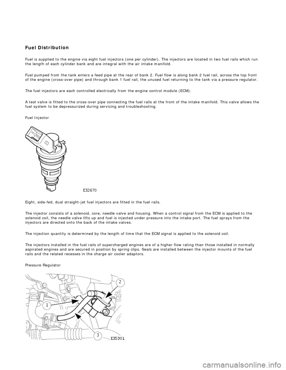
Fuel D
istribution
Fuel is supplied to th
e engine
via eight fuel injectors (one pe r cylinder). The injectors are located in two fuel rails which r un
the length of each cylinder bank and ar e integral with the air intake manifold.
Fuel pumped from the tank enters a feed pipe at the rear of bank 2. Fuel flow is along bank 2 fuel rail, across the top front
of the engine (cross-over pipe) and through bank 1 fuel rail, the unused fuel re turning to the tank via a pressure regulator.
The fuel injectors are each controlled electrically from the engine control module (ECM).
A test valve is fitted to the cross-over pipe connecting the fu el rails at the front of the intake manifold. This valve allows the
fuel system to be depr essurized during servicin g and troubleshooting.
Fuel Injector
Eight, side-fed, dual straight-jet fuel injectors are fi tted in the fuel rails.
The injector consists of a solenoid, core, needle valve and ho using. When a control signal from the ECM is applied to the
solenoid coil, the needle valve lifts up and fuel is injected under pressure into the intake port. The fuel sprays from the
injectors are directed onto the back of the intake valves.
The injection quantity is determined by the length of time that the ECM signal is applied to the solenoid coil.
The injectors installed in the fuel rails of supercharged engines are of a higher flow rating than those installed in normally
aspirated engines and are secured in position by spring clips. Seals are instal led between the injector mounts of the fuel
rails and the related re cesses in the charge air cooler adaptors.
Pressure Regulator
Page 1020 of 2490
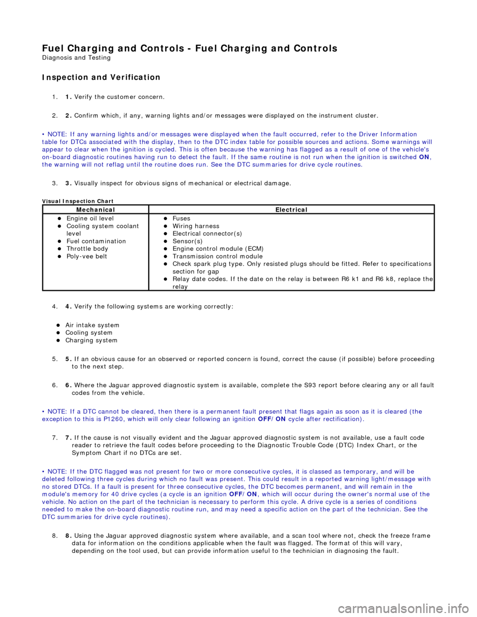
Fuel Char
ging and Controls - Fuel Charging and Controls
D
iagn
osis and Testing
I
n
spection and Verification
1.
1. Veri fy the customer concern.
2. 2. Confi
rm which, if any, warning li
ghts and/or messages were displayed on the instrument cluster.
• NOTE: If any warning lights and/or me ssages were displayed when the fault occurred, refer to the Driver Information
table for DTCs associated with the display, then to the DTC index table for possible sources and actions. Some warnings will
appear to clear when the ignition is cycl ed. This is often because the warning has flagged as a resu lt of one of the vehicle's
on-board diagnostic routines having run to detect the fault. If the same routine is not run when the ignition is switched ON,
the warning will not reflag until the routine does run. See the DTC summaries for drive cycle routines.
3. 3. Visually inspect for obvious signs of mechanical or electrical damage.
Vi
sual Inspection Chart
4.
4. Veri fy the foll
owing syst
ems are working correctly:
Air intake
system
Cooling system
Charging system
5. 5. If
an obvious cause for an observed or
reported concern is found, correct th e cause (if possible) before proceeding
to the next step.
6. 6. Where the Jaguar approved diagnostic sy stem is available, complete the S93 report before clearing any or all fault
codes from the vehicle.
• NOTE: If a DTC cannot be cleared, then there is a permanent fault present that flag s again as soon as it is cleared (the
exception to this is P1260, which will only clear following an ignition OFF/ON cycle after rectification).
7. 7. If the cause is not visually evident and the Jaguar approv ed diagnostic system is not available, use a fault code
reader to retrieve the fault codes be fore proceeding to the Diagnostic Trou ble Code (DTC) Index Chart, or the
Symptom Chart if no DTCs are set.
• NOTE: If the DTC flagged was not present for two or more co nsecutive cycles, it is classed as temporary, and will be
deleted following three cycl es during which no fault was present. This could result in a reported wa rning light/message with
no stored DTCs. If a fault is present for three consecutive cycles, the DTC becomes permanent, and will remain in the
module's memory for 40 drive cycl es (a cycle is an ignition OFF/ON, which will occur during the owner's normal use of the
vehicle. No action on the part of the technician is necessary to perform this cycle. A drive cycle is a series of conditions
needed to make the on-board diagnostic ro utine run, and may need a specific action on the part of the technician. See the
DTC summaries for drive cycle routines).
8. 8. Using the Jaguar approved diagnostic system where available, and a scan tool where not, check the freeze frame
data for information on the conditions applicable when the fault was flagged. The format of this will vary,
depending on the tool used, but can pr ovide information useful to the technician in diagnosing the fault.
MechanicalElectrical
Engine
oil level
Coo
ling system coolant
lev
el
Fuel contamination
Throttle body Poly-ve
e belt
Fu
ses
W
i
ring harness
E
l
ectrical connector(s)
Sens
o
r(s)
Engine
control module (E
CM)
Tran
s
mission control module
Check spark plu
g type. Only r
e
sisted plugs should be fitted. Refer to specifications
section for gap
Relay date codes. I
f the date on the rela
y is between R6 k1 and R6 k8, replace the
relay
Page 1021 of 2490
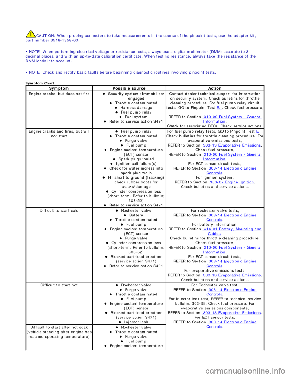
CAUTI
ON: When probing connectors to take
measurements in the course of the pinpoint tests, use the adaptor kit,
part number 3548-1358-00.
• NOTE: When performing electrical voltag e or resistance tests, always use a digital multimeter (DMM) accurate to 3
decimal places, and with an up-t o-date calibration certificate. When testing resistance, always take the resistance of the
DMM leads into account.
• NOTE: Check and rectify basic faults before beginning diagnostic ro utines involving pinpoint tests.
Sy
mptom Chart
Sy
mptom
Possib
le source
Acti
on
Engine
cranks, but does not fire
Secu
rity system /Immobiliser
engaged
Thr
ottle contaminated
Harness damage
F
uel pump relay
Fue
l system
R
efer to service action S491
Contact dealer techn
ical
support for information
on security system. Chec k bulletins for throttle
cleaning procedure. For fuel pump relay circuit
tests, GO to Pinpoint Test E.
.
Check fuel pressure,
REFER to Section 310
-00
Fuel System
- Gen
eral
Informati
on
.
Chec
k for associated DTCs
. Check service actions.
Engine
cranks and fires, but will
not start
F
uel pump relay
Thr
ottle contaminated
Purge
valve
Fue
l pump
Engine coolan
t temperature
(ECT) sensor
Spark plugs
fouled
Ignition coil
failure(s)
Check f
or water ingress into
spark plug wells
HT sho
rt to ground (tracking)
check rubber boots for cracks/damage
Cyl
inder compression loss
(short-term. Refer to bulletin;
303-52)
R
efer to service action S491
F
or fuel pump relay tests,
GO to Pinpoint Test E.
.
Check bull
etins for throttle cleaning procedure. For
evaporative emissions tests,
REFER to Section 303
-1
3 Evaporative Emissions
. Chec
k fuel pressure,
REFER to Section 310
-00
Fuel System
- Ge
neral
Informati
on
.
F
or ECT sensor circuit tests,
REFER to Section 303
-14 Elec
tronic Engine
Controls.
For ign
ition system,
REFER to Section 303
-07
Engine Ignition
.
Check bulletins an d service
actions.
D
ifficult to start cold
Roc
hester valve
Batt
ery
Thr
ottle contaminated
Fue
l pump
Engine coolan
t temperature
(ECT) sensor
Purge
valve
Cyl
inder compression loss
(short-term. Refer to bulletin;
303-52)
Blocked part-load breather (
service action S474)
R
efer to service action S491
F
or rochester valve tests,
REFER to Section 303
-14 Elec
tronic Engine
Controls.
F
or battery information,
REFER to Section 414
-0
1 Battery, Mounting and
Cables.
Check bull
etins for throttle cleaning procedure.
Check fuel pressure,
REFER to Section 310
-00
Fuel System
- Ge
neral
Informati
on
.
F
or ECT sensor circuit tests,
REFER to Section 303
-14 Elec
tronic Engine
Controls.
For evaporat
ive emissions tests,
REFER to Section 303
-1
3 Evaporative Emissions
. Check bulletins an
d
service actions.
D
ifficult to start hot
Roc
hester valve
Purge
valve
Thr
ottle contaminated
Fue
l pump
Engine coolan
t temperature
(ECT) sensor
Blocked part-load breather (
service action S474)
Injec
tor leak
F
or Rochester
valve test,
REFER to Section 303
-14 Elec
tronic Engine
Controls.
Fo
r injector leak test, REFER to technical service
bulletin, 303-39. Check fuel pressure, For evaporative emissions components,
REFER to Section 303
-1
3 Evaporative Emissions
. F
or ECT sensor tests,
REFER to Section 303
-14 Elec
tronic Engine
Controls. D
ifficult to start after hot soak
(vehicle standing after engine has
reached operating temperature)
Roc
hester valve
Thr
ottle contaminated
Purge
valve
Fue
l pump
Engine coolan
t temperature
Page 1022 of 2490
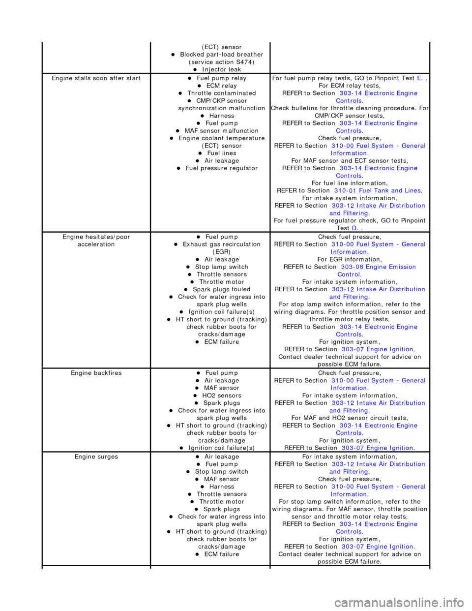
(ECT) se
nsor
Blocked part-load breather
(s
ervice action S474)
Injec
t
or leak
Engine stalls
soon
after start
F
u
el pump relay
ECM relay Thr
o
ttle contaminated
CMP/CKP sen
s
or
synchronization malfunction
Harness Fuel
pump
MAF
s
ensor malfunction
Engine coolan
t
temperature
(ECT) sensor
Fue l
lines
Air leakage Fu
el pressure regulator
F
o
r fuel pump relay tests,
GO to Pinpoint Test E.
.
F or ECM
relay tests,
REFER to Section 303
-14 Elec tronic En
gine
Controls.
Check bull etins for throttl
e cleaning procedure. For
CMP/CKP sensor tests,
REFER to Section 303
-14 Elec tronic En
gine
Controls.
Chec k fu
el pressure,
REFER to Section 310
-00 Fu
el System
- Ge
n
eral
Informati
o
n
.
F or MAF sensor and
ECT sensor tests,
REFER to Section 303
-14 Electronic En
gine
Controls.
For fuel l
ine information,
REFER to Section 310
-01
Fuel Tank and Lines
.
F or i
ntake system information,
REFER to Section 303
-1 2
Intake Air Distribution
and F
ilt
ering
.
F o
r fuel pressure regulato
r check, GO to Pinpoint
Test D.
.
Engine h e
sitates/poor
acceleration
Fue l
pump
Exhaus
t gas
recirculation
(EGR)
Air leakage Stop lamp swi t
ch
Throttl
e
sensors
Throttl
e
motor
Spark plugs
fouled
Check f
o
r water ingress into
spark plug wells
Ignition coil fail
ure(s)
HT sho
rt to ground (tracking)
check rubber
boots for
cracks/damage
ECM failu r
e
Chec
k fu
el pressure,
REFER to Section 310
-00 Fu
el System
- Ge
n
eral
Informati
o
n
.
F o
r EGR information,
REFER to Section 303
-08 En gin
e Emission
Control.
F or i
ntake system information,
REFER to Section 303
-1 2
Intake Air Distribution
and F
ilt
ering
.
F or stop l
amp switch in
formation, refer to the
wiring diagrams. For throttle position sensor and throttle motor relay tests,
REFER to Section 303
-14 Elec tronic En
gine
Controls.
For ign i
tion system,
REFER to Section 303
-07 En
gine Ignition
.
Contact dealer techn i
cal
support for advice on
possible ECM failure.
Engine ba ckfiresFuel
pump
Air leakage MAF s
e
nsor
HO2 sensors Spark plugs
Check fo
r water ingress into
spark plug wells
HT short to ground (tracking) check rubber
boots for
cracks/damage
Ignition coil fail
ure(s)
Chec
k fu
el pressure,
REFER to Section 310
-00 Fu
el System
- Ge
n
eral
Informati
o
n
.
F or i
ntake system information,
REFER to Section 303
-1 2
Intake Air Distribution
and F
ilt
ering
.
For MAF and HO2
sensor circuit tests,
REFER to Section 303
-14 Electronic En
gine
Controls.
For igni
tion system,
REFER to Section 303
-07 En
gine Ignition
.
Engine
s
urges
Air leakage Fue
l
pump
Stop lamp swi
t
ch
MAF s
e
nsor
Harness Throttl
e
sensors
Throttl
e
motor
Spark plugs
Check fo
r water ingress into
spark plug wells
HT sho rt to ground (tracking)
check rubber
boots for
cracks/damage
ECM failu r
e
F
or i
ntake system information,
REFER to Section 303
-1 2
Intake Air Distribution
and F
ilt
ering
.
Chec k fu
el pressure,
REFER to Section 310
-00 Fu
el System
- Gen
e
ral
Informati
o
n
.
F or stop l
amp switch in
formation, refer to the
wiring diagrams. For MAF se nsor, throttle position
sensor and throttle motor relay tests,
REFER to Section 303
-14 Elec tronic En
gine
Controls.
For ign i
tion system,
REFER to Section 303
-07 En
gine Ignition
.
Contact dealer techn i
cal
support for advice on
possible ECM failure.