1998 JAGUAR X308 engine ignition
[x] Cancel search: engine ignitionPage 1241 of 2490
E
lectronic Engine Controls - Engine
Control Module (ECM) Adaptation
Gen
eral Procedures
When to car
ry out adaptations
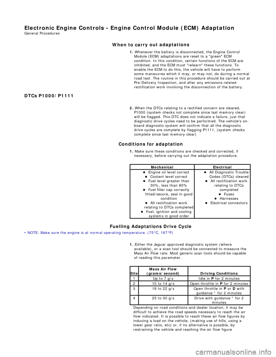
DTCs P1000/P1111 Conditions for adaptation
Fuelling Adaptations Drive Cycle
•
NOTE: Make sure the engine is at normal operating
temperature. (75°C, 167°F) 1.
Whenever the battery is disconnected, the Engine Control
Module (ECM) adaptations are reset to a "green" ECM
condition. In this condition, certain functions of the ECM are
inhibited, and the ECM must "r elearn" these functions. To
enable the ECM to do this, the vehicle will have to perform
some maneuvres which it may, or may not, do during a normal
road test. The routine in this pr ocedure should be carried out at
Pre-Delivery Inspection, and after any emissions related
rectification work involving the disconnection of the battery.
2. When the DTCs relating to a rectified concern are cleared,
P1000 (system checks not complete since last memory clear)
will be flagged. This DTC does no t indicate a failure, just that
diagnostic drive cycles need to be performed. The vehicle's on-
board diagnostic system will confirm that all the diagnostic
drive cycles are complete by flagging P1111, (system checks
complete since last memory clear)
1. Make sure these conditions are checked and corrected, if
necessary, before carrying ou t the adaptation procedure.
MechanicalElectrical
Engi
ne oil level correct
Coo
lant level correct
F
uel level greater than
30%, less than 80%
F
uel filler cap correctly
fitted/secure, seal in good condition
Al
l rectification work
relating to DTCs completed
F
uel, ignition and cooling
systems in good order
Al
l Diagnostic Trouble
Codes (DTCs) cleared
Al
l rectification work
relating to DTCs completed
F
uses
Harnes
ses
E
lectrical connectors
1.
Either
the Jaguar approved diagnostic system (where
available), or a scan tool should be connected to measure the
Mass Air Flow rate. Most generi c scan tools should be capable
of reading this parameter.
Depending on road conditions and dealer location, it may be
difficult to achieve the road sp eeds necessary to reach the air
flow indicated. It is possible to reach these air flow figures by
inducing a load on the vehicle, (making use of hills, using a
lower gear ratio, etc) or, if no alternative is possible, by
restraining the vehicle and re aching the air flow figure
Si
te
Mass Air Flow
(gra
ms/second)
D
riving Conditions
1Up t
o 7 g/s
Idle
in
P for 2 minutes
21
0 to 14 g/s
O
pen throttle in
P for 2 minutes
31
8 to 22 g/s
O
pen throttle in
P or D with
guidance * for 2 minutes
42
5 to 30 g/s
D
rive with guidance * for 2
minutes
Page 1269 of 2490
2.2. Check on non-volatile diagnostic memory by wr iting a test pattern and then reading it back.
3. 3. Internal 'watchdog' hardware to check whether the TCM has crashed.
Transmission Control Module Supply Voltage
The TCM monitors battery and igni tion switched supply voltages.
A permanent supply is used to maintain a battery backed 'memor y'. Should this supply be cut, due to battery disconnection
perhaps, the 'adaptive shift' valu es will be lost. This will result in a small reduction in shift quality for a period until th e
adaptions are 're-learned'
The TCM will adopt 'limp home' mode as a result of the supply voltage being >16V or <7V with an engine speed >1600
rpm.
Should the ignition supply be >7V but <9V the TCM will hold the gear that it has currently selected. If after 2.5 seconds,
with the engine speed >1600 rpm, the voltage remains at this level, 'limp home' mode will be adopted. The 2.5 second
delay is built in to prevent reaction to a momentary voltage fluctuation.
Operation
CAUTION: Disconnection of the TCM and / or the vehicle batt ery will cause system adaptions to be lost; this may be
apparent by shift quality degradation. Fo llowing reconnection, a period of 'varied' driving will reinstate adaptions and thus
normal operation. Please ensure that the customer is made aware that the adaption period is variable and may occur after
handover, as the transmission re-learns the prevailing driving style.
• NOTE: Should the TCM fail, please ensure that the control housing cooling fan is operating correctly. Failure of the cooling
fan MUST be rectified before renewing the TCM and details of a fan fa ilure should accompany the returned TCM.
The TCM processes information received in both analogue and digital form, such as:
Transmission input speed Transmission output speed Throttle position Pedal demand Gear selector position Engine torque Engine speed Transmission oil temperature Mode switch
This information is then used by the TC M to control shift energy management and decide which shift program to implement
and which gear to select.
The TCM uses the various sensors and inpu ts to monitor the correct operation of the system an d is programmed to take
default action and inform the operator when a fault occurs.
Safety Functions
The safety functions are designed to safeguard against inappr opriate actions by the operator as well as against system
malfunctions. The system prevents reve rse gear from being engaged at high forward speeds and prevents manual
downshifting at excessive engine speeds; these functions are not operational in mechanical limp-home mode.
The TCM constantly monitors the transmissi on for faults. In the event of a problem the TCM will adopt a 'limp home' mode
in which only P R N D - (selector in D but only fourth gear is enabled) are available. The operator will be made aware of
certain faults by an in strument panel warning.
The electrical and diagnostic system has been designed such that system integrity is protected at all times, the safety
concept being based on th e following three points:
Page 1277 of 2490
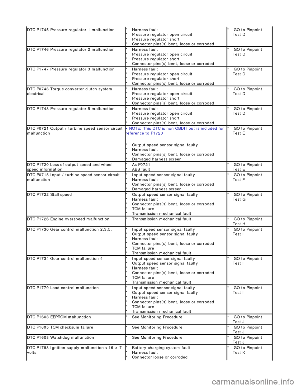
DTC P1745 Pressure regulator 1 malfunctionHarness fault
Pressure regulator open circuit
Pressure regulator short
Connector pins(s) bent, loose or corroded
*
*
*
*GO to Pinpoint
Test D
*
DTC P1746 Pressure regulator 2 malfunctionHarness fault
Pressure regulator open circuit
Pressure regulator short
Connector pins(s) bent
, loose or corroded
*
*
*
*GO to Pinpoint
Test D
*
DTC P1747 Pressure regulator 3 malfunctionHarness fault
Pressure regulator open circuit
Pressure regulator short
Connector pins(s) bent
, loose or corroded
*
*
*
*GO to Pinpoint
Test D
*
DTC P0743 Torque converter clutch system
electricalHarness fault
Pressure regulator open circuit
Pressure regulator short
Connector pins(s) bent
, loose or corroded
*
*
*
*GO to Pinpoint
Test D
*
DTC P1748 Pressure regulator 5 malfunctionHarness fault
Pressure regulator open circuit
Pressure regulator short
Connector pins(s) bent
, loose or corroded
*
*
*
*GO to Pinpoint
Test D
*
DTC P0721 Output / turbine speed sensor circuit
malfunction• NOTE: This DTC is non OBDII but is included for
reference to P1720
Output speed sensor signal faulty
Harness fault
Connector pins(s) bent , loose or corroded
Damaged harness screen
*
*
*
*GO to Pinpoint
Test E
*
DTC P1720 Loss of output speed and wheel
speed informationAs P0721
ABS fault
*
*GO to Pinpoint
Test E
*
DTC P0715 Input / turbine speed sensor circuit
malfunctionInput speed sensor signal faulty
Harness fault
Connector pins(s) bent
, loose or corroded
Damaged harness screen
*
*
*
*GO to Pinpoint
Test F
*
DTC P1722 Stall speedOutput speed sensor signal faulty
Harness fault
Connector pins(s) bent
, loose or corroded
TCM failure
Transmission mechanical fault
*
*
*
*
*GO to Pinpoint
Test G
*
DTC P1726 Engine overspeed malfunctionTransmission mechanical fault
*GO to Pinpoint
Test H
*
DTC P1730 Gear control malfunction 2,3,5,Input speed sensor signal faulty
Output speed sensor signal faulty
Harness fault
Connector pins(s) bent
, loose or corroded
TCM failure
Transmission mechanical fault
*
*
*
*
*
*GO to Pinpoint
Test I
*
DTC P1734 Gear control malfunction 4Input speed sensor signal faulty
Output speed sensor signal faulty
Harness fault
Connector pins(s) bent
, loose or corroded
TCM failure
Transmission mechanical fault
*
*
*
*
*
*GO to Pinpoint
Test I
*
DTC P1779 Load control malfunctionInput speed sensor signal faulty
Output speed sensor signal faulty
Harness fault
Connector pins(s) bent
, loose or corroded
TCM failure
Transmission mechanical fault
*
*
*
*
*
*GO to Pinpoint
Test I
*
DTC P1603 EEPROM malfunctionSee Monitoring Procedure
*GO to Pinpoint
Test J
*
DTC P1605 TCM checksum failureSee Monitoring Procedure
*GO to Pinpoint
Test J
*
DTC P1608 Watchdog malfunctionSee Monitoring Procedure
*GO to Pinpoint
Test J
*
DTC P1793 Ignition supply malfunction >16 < 7
voltsBattery charging system fault
Harness fault
Connector loose or corroded
*
*
*GO to Pinpoint
Test K
*
Page 1278 of 2490
Pinpoint test A: P0741, P0742, P0743
Pinpoint test B: P0743
Connector pin(s) bent or tracking between
connections
*
DTC P1789 Ignition supply malfunction >7 < 9
voltsBattery charging system fault
Blown fuse
Harness fault
Connector loose or corroded
Connector pin(s) bent or tracking between
connections Ground fault
*
*
*
*
*
*GO to Pinpoint
Test K
*
DTC P0710 Transmission fluid temperature
sensor malfunctionDamaged sensor
Sensor out of range / short
Harness open circuit
Harness short
Connector loose or corroded
*
*
*
*
*GO to Pinpoint
Test L
*
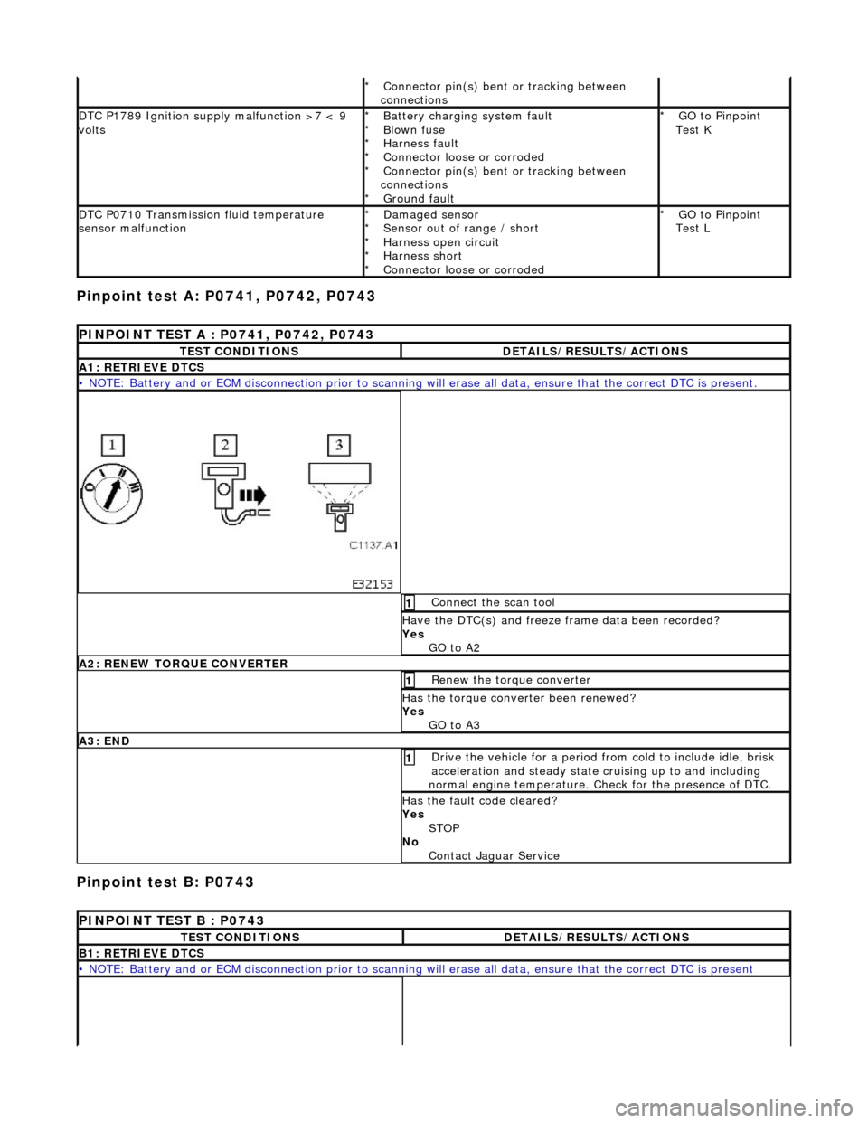
PINPOINT TEST A : P0741, P0742, P0743
TEST CONDITIONSDETAILS/RESULTS/ACTIONS
A1: RETRIEVE DTCS
• NOTE: Battery and or ECM disconnection prior to scanning wi
ll erase all data, ensure that the correct DTC is present.
Connect the scan tool 1
Have the DTC(s) and freeze frame data been recorded?
Yes GO to A2
A2: RENEW TORQUE CONVERTER
Renew the torque converter 1
Has the torque converter been renewed?
Yes GO to A3
A3: END
Drive the vehicle for a period from cold to include idle, brisk
acceleration and steady state cruising up to and including
normal engine temperature. Check for the presence of DTC. 1
Has the fault code cleared?
Yes STOP
No Contact Jaguar Service
PINPOINT TEST B : P0743
TEST CONDITIONSDETAILS/RESULTS/ACTIONS
B1: RETRIEVE DTCS
• NOTE: Battery and or ECM disconnection prior to scanning wi ll erase all data, ensure that the correct DTC is present
Page 1295 of 2490
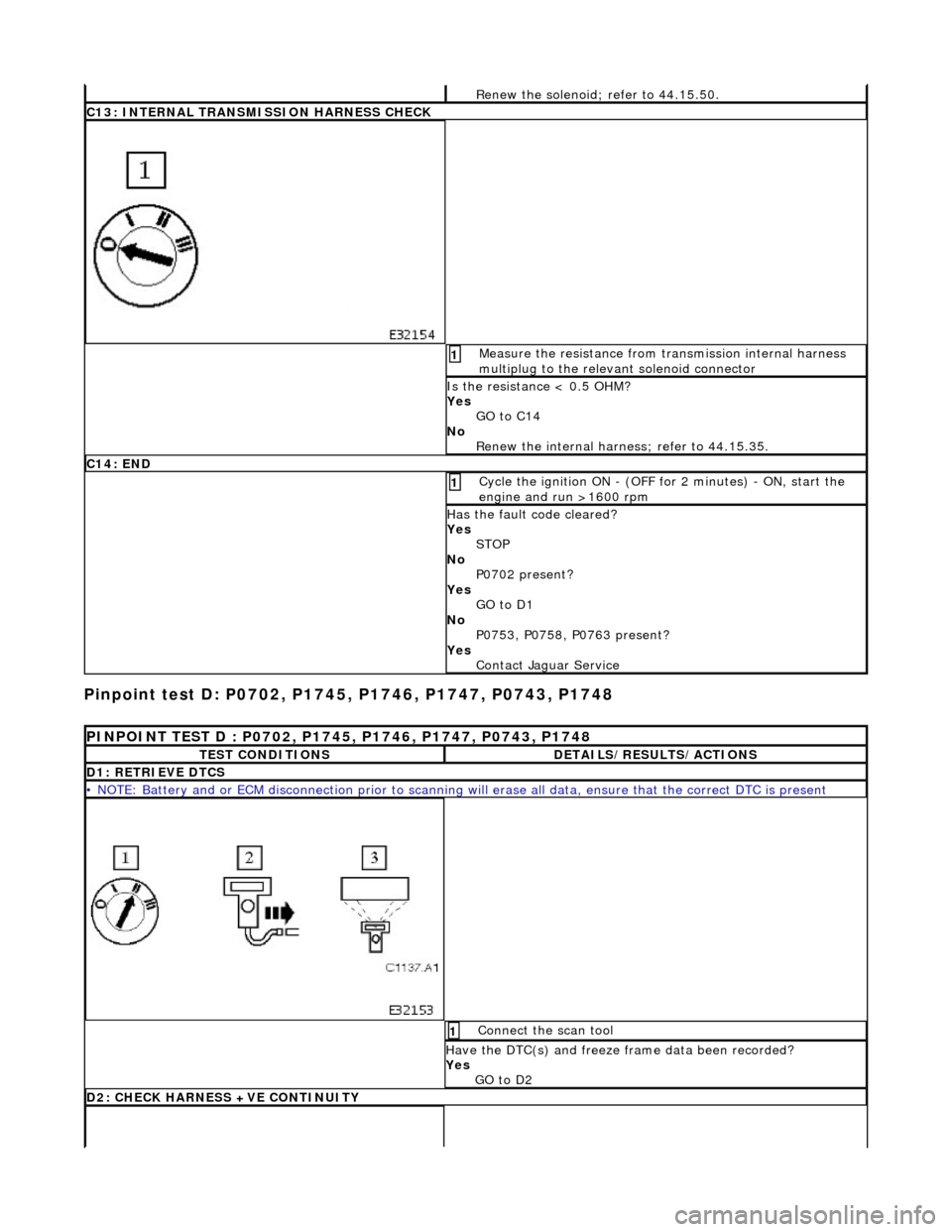
Pinpoint test D: P0702, P1745, P1746, P1747, P0743, P1748
Renew the solenoid; refer to 44.15.50.
C13: INTERNAL TRANSMISSION HARNESS CHECK
Measure the resistance from transmission internal harness
multiplug to the relevant solenoid connector 1
Is the resistance < 0.5 OHM?
Yes GO to C14
No Renew the internal harnes s; refer to 44.15.35.
C14: END
Cycle the ignition ON - (OFF for 2 minutes) - ON, start the
engine and run >1600 rpm 1
Has the fault code cleared?
Yes
STOP
No P0702 present?
Yes GO to D1
No P0753, P0758, P0763 present?
Yes Contact Jaguar Service
PINPOINT TEST D : P0702, P1745, P1746, P1747, P0743, P1748
TEST CONDITIONSDETAILS/RESULTS/ACTIONS
D1: RETRIEVE DTCS
• NOTE: Battery and or ECM disconnection prior to scanning wi ll erase all data, ensure that the correct DTC is present
Connect the scan tool 1
Have the DTC(s) and freeze frame data been recorded?
Yes GO to D2
D2: CHECK HARNESS +VE CONTINUITY
Page 1306 of 2490
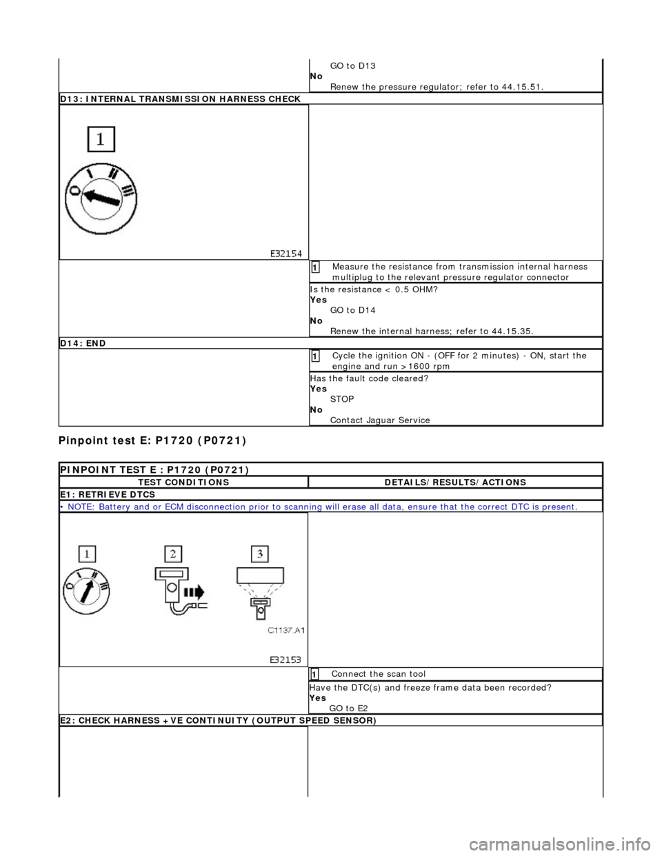
Pinpoint test E: P1720 (P0721)
GO to D13
No Renew the pressure regulator; refer to 44.15.51.
D13: INTERNAL TRANSMISSION HARNESS CHECK
Measure the resistance from transmission internal harness
multiplug to the relevant pr essure regulator connector 1
Is the resistance < 0.5 OHM?
Yes
GO to D14
No Renew the internal harnes s; refer to 44.15.35.
D14: END
Cycle the ignition ON - (OFF for 2 minutes) - ON, start the
engine and run >1600 rpm 1
Has the fault code cleared?
Yes
STOP
No Contact Jaguar Service
PINPOINT TEST E : P1720 (P0721)
TEST CONDITIONSDETAILS/RESULTS/ACTIONS
E1: RETRIEVE DTCS
• NOTE: Battery and or ECM disconnection prior to scanning wi ll erase all data, ensure that the correct DTC is present.
Connect the scan tool 1
Have the DTC(s) and freeze frame data been recorded?
Yes GO to E2
E2: CHECK HARNESS +VE CONTIN UITY (OUTPUT SPEED SENSOR)
Page 1332 of 2490
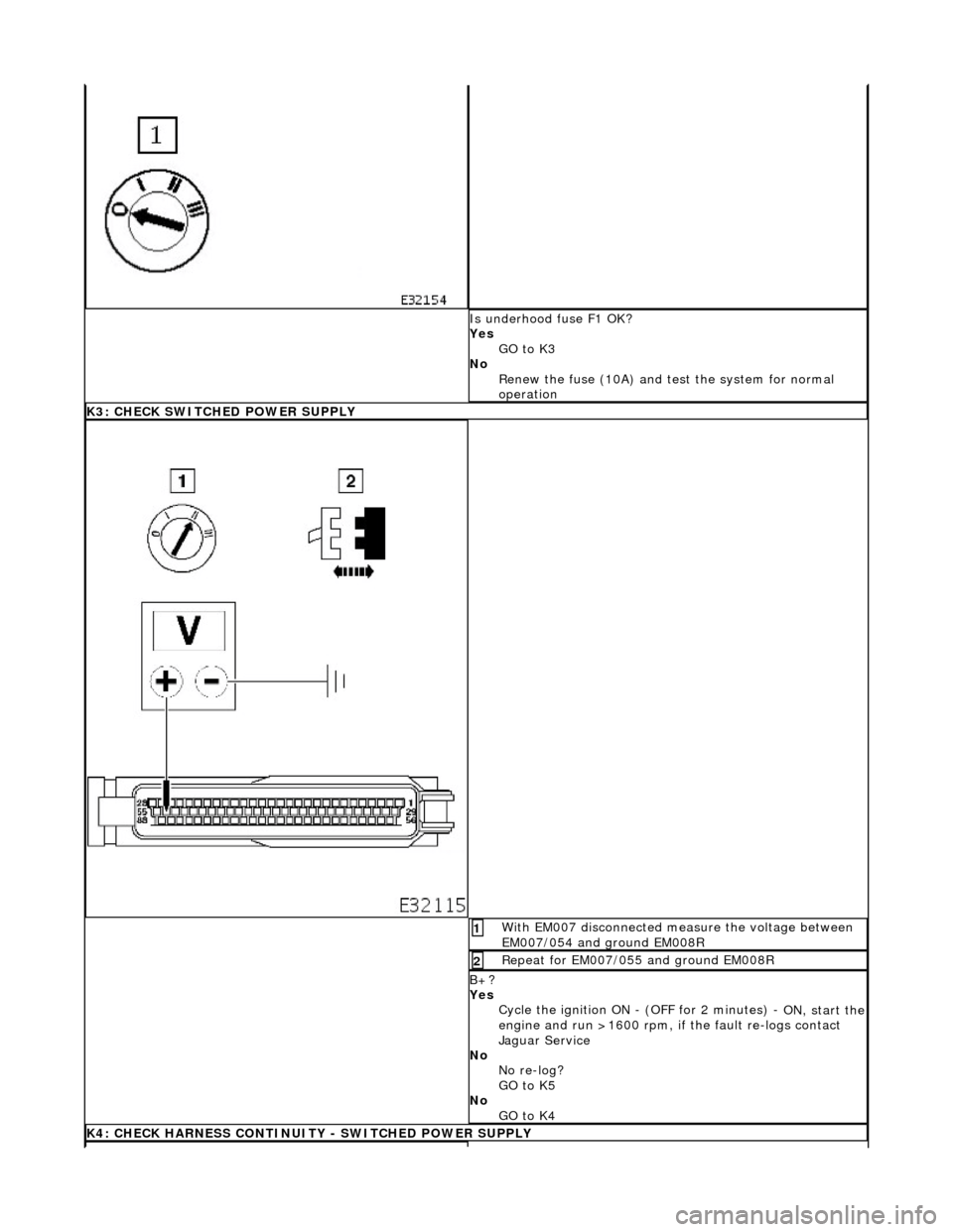
Is underhood fuse F1 OK?
Yes GO to K3
No Renew the fuse (10A) and te st the system for normal
operation
K3: CHECK SWITCHED POWER SUPPLY
With EM007 disconnected measure the voltage between
EM007/054 and ground EM008R 1
Repeat for EM007/055 and ground EM008R 2
B+?
Yes Cycle the ignition ON - (OFF for 2 minutes) -
ON, start the engine and run >1600 rpm, if the fault re-logs contact
Jaguar Service
No No re-log?
GO to K5
No GO to K4
K4: CHECK HARNESS CONTINUITY - SWITCHED POWER SUPPLY
Page 1336 of 2490
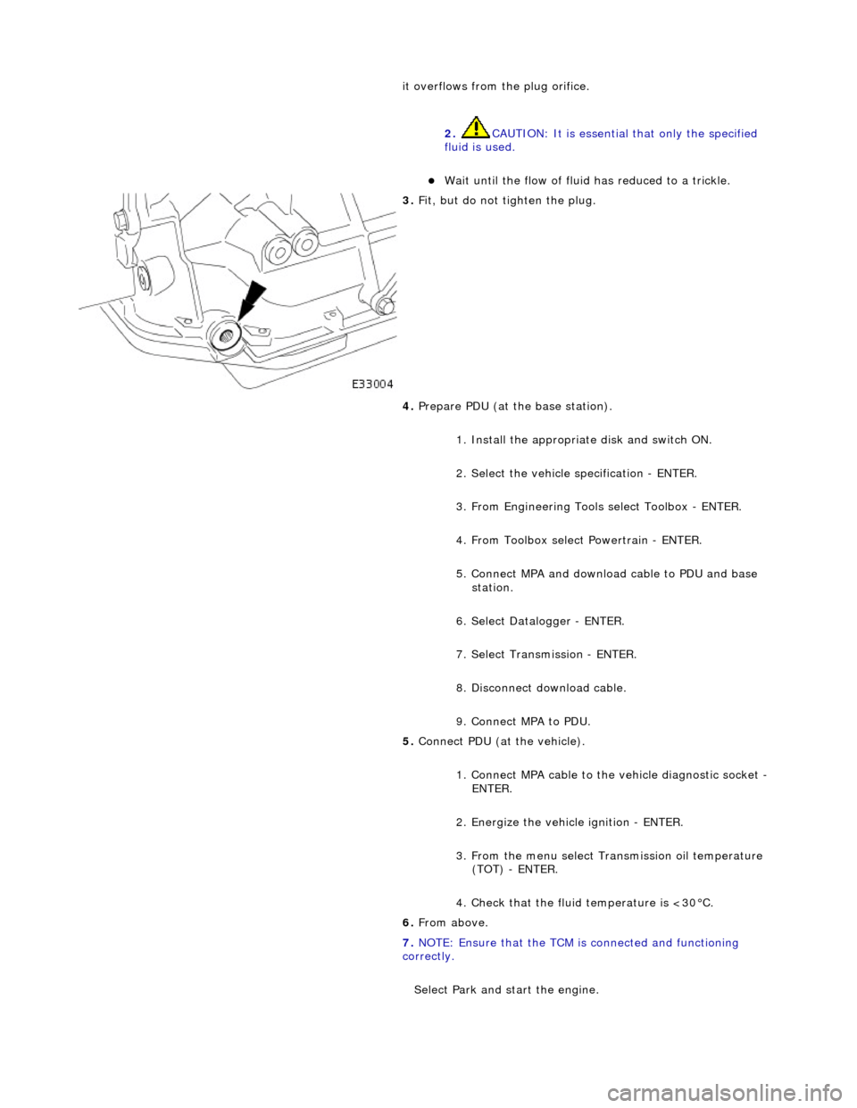
it overflows from the plug orifice. 2. CAUTION: It is essential that only the specified
fluid is used.
Wait until the flow of fluid has reduced to a trickle.
3. Fit, but do not tighten the plug.
4. Prepare PDU (at the base station).
1. Install the appropriat e disk and switch ON.
2. Select the vehicle specification - ENTER.
3. From Engineering Tools select Toolbox - ENTER.
4. From Toolbox select Powertrain - ENTER.
5. Connect MPA and download cable to PDU and base station.
6. Select Datalogger - ENTER.
7. Select Transmission - ENTER.
8. Disconnect download cable.
9. Connect MPA to PDU.
5. Connect PDU (at the vehicle).
1. Connect MPA cable to the vehicle diagnostic socket -
ENTER.
2. Energize the vehicle ignition - ENTER.
3. From the menu select Transmission oil temperature (TOT) - ENTER.
4. Check that the fluid temperature is <30°C.
6. From above.
7. NOTE: Ensure that the TCM is connected and functioning
correctly.
Select Park and start the engine.