Page 1037 of 2490
Fuel Ch
arging and Controls
- Fuel Injector4.0L NA V8 - AJ27/3.2L NA V8 -
AJ26
Re
moval and Installation
Remov
al
S
pecial Tool(s)
R
emover - Fuel Injector
303-539 (JD 231)
1. Disconnect battery ground cable (IMPORTANT, see SRO
86.15.19 for further information).
2. WARNING: BEFORE PROCEEDING, IT IS ESSENTIAL THAT
THE WARNING NOTES GIVEN IN SECTION 100-00 (UNDER THE
HEADING 'SAFETY PRECAUTIONS') ARE READ AND
UNDERSTOOD.
Depressurize the fuel sy stem; refer to 19.50.02.
3. R
emove engine covers.
4. Di
sconnect bank 1 or 2 inject
or connectors and reposition
harness to allow access to injectors.
5. Remove bolts which secure fuel injector clamp plate to inlet
manifold.
Page 1039 of 2490

Fuel Charging and Controls
- Fuel Injector4.0L SC V8 - AJ26
Rem
oval and Installation
Remov
al
Installation
1.
Disconnect battery ground cabl e (IMPORTANT, see SRO 86.15.19
for further information).
2. WARNING: BEFORE PROCEEDING, IT IS ESSENTIAL THAT
THE WARNING NOTES GIVEN IN SECTION 100-00 (UNDER THE
HEADING 'SAFETY PRECAUTIONS') ARE READ AND UNDERSTOOD.
Depressurize fuel system; refer to 19.50.02.
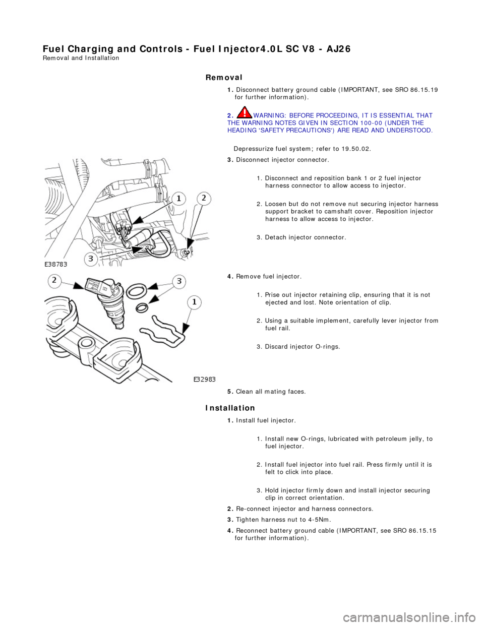
3.
Disconnect injector connector.
1. Disconnect and reposition bank 1 or 2 fuel injector harness connector to allow access to injector.
2. Loosen but do not remove nut securing injector harness support bracket to camshaft cover. Reposition injector
harness to allow access to injector.
3. Detach injector connector.
4.
Remove fuel injector.
1. Prise out injector retaining clip, ensuring that it is not ejected and lost. Note orientation of clip.
2. Using a suitable implement, carefully lever injector from
fuel rail.
3. Discard injector O-rings.
5. Clean all mating faces.
1. Install fuel injector.
1. Install new O-rings, lubricat ed with petroleum jelly, to
fuel injector.
2. Install fuel injector into fuel rail. Press firmly until it is felt to click into place.
3. Hold injector firmly down and install injector securing clip in correct orientation.
2. Re-connect injector and harness connectors.
3. Tighten harness nut to 4-5Nm.
4. Reconnect battery ground cable (IMPORTANT, see SRO 86.15.15
for further information).
Page 1040 of 2490

Fuel Char
ging and Controls - Fu
el Injectors4.0L SC V8 - AJ26
Remo
val and Installation
Remov
a
l
Installation
1. Disc onne
ct battery ground cable (IMPORTANT, see SRO
86.15.19 for further information).
2. WARNING: BEFORE PROCEEDING, IT IS ESSENTIAL THAT
THE WARNING NOTES GIVEN IN SECTION 100-00 (UNDER THE
HEADING 'SAFETY PRECAUTIONS') ARE READ AND
UNDERSTOOD.
Depressurize fuel syst em; refer to 19.50.02.
3. Drain radiator coolant; refer to 2
6.10.01.
4. Remove air cleaner cover / inta ke assembly; refer 19.10.30.
5. Remove throttle body; refer to 19.70.04.
6. Remove throttle induction elbo w; refer to (SC) 19.70.28.
7. Remove exhaust gas re-circulation valve (EGR) if fitted; refer
to 17.45.01.
8. Remove supercharger outlet duct and gasket; refer to
18.50.16.
9. Remove coolant outlet pipe; refer to (SC) 26.31.08 .
10. Remove supercharger drive belt; refer to 18.50.08.
11. Remove supercharger assembly; refer to 18.50.15.
12. Remove bank 1 or 2 charge air cooler as required; refer to
18.50.18 and / or 18.50.19.
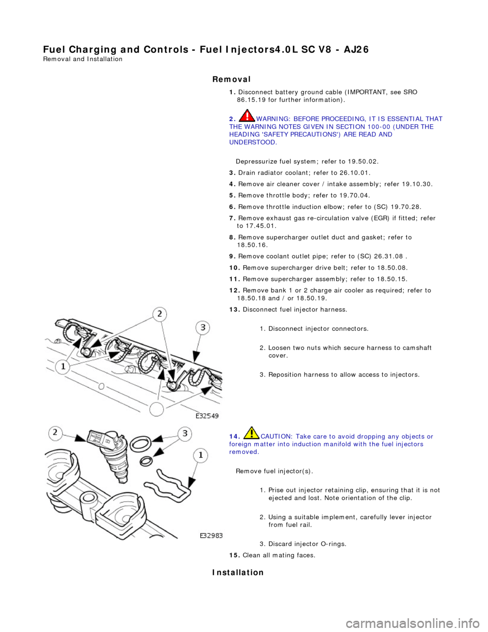
13 . Di
sconnect fuel injector harness.
1. Disconnect injector connectors.
2. Loosen two nuts which se cure harness to camshaft
cover.
3. Reposition harness to al low access to injectors.
14. CAUTI
ON: Take care to avoi
d dropping any objects or
foreign matter into induction ma nifold with the fuel injectors
removed.
Remove fuel injector(s). 1. Prise out injector retaining clip, ensuring that it is not
ejected and lost. Note orientation of the clip.
2. Using a suitable implemen t, carefully lever injector
from fuel rail.
3. Discard injector O-rings.
15 . Cle
an all mating faces.
Page 1041 of 2490

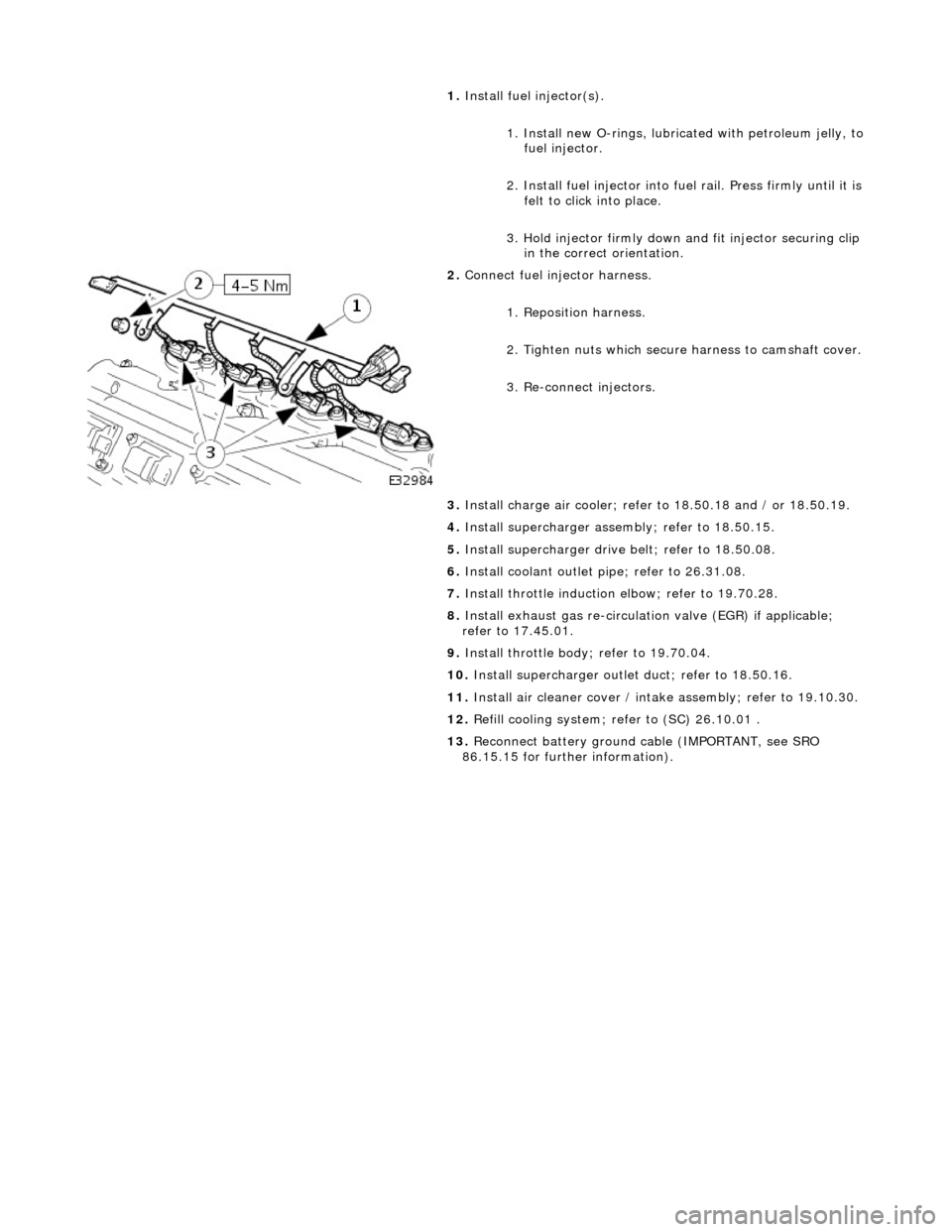
1.
Install
fuel injector(s).
1. Install new O-rings, lubricated with petroleum jelly, to
fuel injector.
2. Install fuel in jector into fuel rail. Press firmly until it is
felt to click into place.
3. Hold injector firmly down and fit injector securing clip
in the correct orientation.
2. Conne
ct fuel injector harness.
1. Reposition harness.
2. Tighten nuts which secure harness to camshaft cover.
3. Re-connect injectors.
3. Install charge air c ooler; refer to 18.50.18 and / or 18.50.19.
4. Install supercharger asse mbly; refer to 18.50.15.
5. Install supercharger driv e belt; refer to 18.50.08.
6. Install coolant outlet pi pe; refer to 26.31.08.
7. Install throttle induction elbow; refer to 19.70.28.
8. Install exhaust gas re-circulation valve (EGR) if applicable;
refer to 17.45.01.
9. Install throttle body ; refer to 19.70.04.
10. Install supercharger outlet duct; refer to 18.50.16.
11. Install air cleaner cover / intake assembly; re fer to 19.10.30.
12. Refill cooling system; refer to (SC) 26.10.01 .
13. Reconnect battery ground cable (IMPORTANT, see SRO
86.15.15 for further information).
Page 1042 of 2490
Fuel Char
ging and Controls - Throttle Body
Re
mo
val and Installation
Remov
a
l
• C
A
UTIONS:
When the throttle body is being replaced by a unit with the part number suffix ' BA', and carrying a sticker such as the
illustration below, then the usual cleaning procedure is NOT to be carried out. These thro ttle bodies have a molykote
coating which will be damaged by normal cleaning procedures. Refer to the latest service action s for further information.
This process assumes the use of the original throttle ca ble. The cable setting procedure in this instance is NOT
appropriate for a new cable; see 19.20.06.
1. Disc onne
ct battery ground cable (IMPORTANT, see SRO
86.15.19 for further information).
2. Remove air cleaner cover / in take assembly; refer 19.10.30
3. Disc
onnect connectors and vacuum pipe.
4. Ro
tate throttle quadrant to allow disconnection of inner cable.
5. NOTE: Do not disturb adjusting nut
Release throttle cable locking nut and displace outer cable from
Page 1048 of 2490
Fuel Charging and Controls - Throt
tle Body Gasket
Re
mo
val and Installation
Remov
a
l
Installation
1.
Re
move throttle body; refer to 19.70.04.
1. Installation is a reversal of the removal procedure.
Page 1067 of 2490

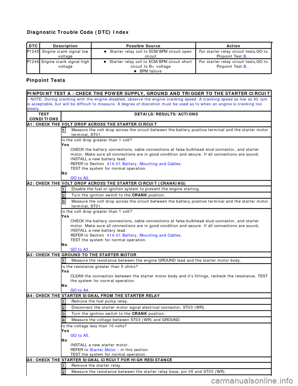
Pinpoint Tests
DT
C
De
scription
Possib
le Source
Acti
on
P1245Engine
crank signal low
voltage
Starter relay
coil to
ECM/BPM circuit open
circuit
F
or starter relay circuit tests,GO to
Pinpoint Test B.
.
P1246Engine
crank signal high
voltage
Starter relay
coil to ECM/BPM circuit short
circuit to B+ voltage
B
PM failure
F
or starter relay circuit tests,GO to
Pinpoint Test B.
.
P
INPOINT TEST A : CHECK THE
POWER SUPPLY, GROUND AND TRI GGER TO THE STARTER CIRCUIT
•
NOTE: During cranking with the engine disabled, observe the engine cranking speed. A cranking speed as low as 90 rpm
is acceptable, but will be difficult to measure. A degree of discretion must be used as to when an engine is cranking too
slowly.
TE
ST
CONDITIONS
D
ETAILS/RESULTS/ACTIONS
A1: CHECK
THE VOLT DROP AC
ROSS THE STARTER CIRCUIT
M
easure the volt drop across the circuit between the battery positive terminal and the starter motor
terminal, ST01.
1
Is the vol
t drop greater than 1 volt?
Yes CHECK the battery connections, cable connections at false bulkhead stud connector, and starter
motor. Make sure all connections are in good co ndition and secure. If all connections are sound,
INSTALL a new battery lead.
REFER to Section 414
-0
1 Battery, Mounting and Cables
.
TEST the system
for normal operation.
No GO to A2
.
A2: CHECK
THE VOLT DROP ACROSS
THE STARTER CIRCUIT (CRANKING)
Di
sable the fuel or ignition system to prevent the engine starting.
1
Turn the ignition swi
tch to the CRANK
position.
2
M
easure the volt drop across the circuit between the battery positive terminal and the starter motor
terminal, ST01.
3
Is the vol
t drop greater than 1 volt?
Yes CHECK the battery connections, cable connections at false bulkhead stud connector, and starter
motor. Make sure all connections are in good co ndition and secure. If all connections are sound,
INSTALL a new battery lead.
REFER to Section 414
-0
1 Battery, Mounting and Cables
.
TEST the system
for normal operation.
No GO to A3
.
A3:
CHECK THE GROUND TO THE STARTER MOTOR
Meas
ure the resistance between the engine GROUND lead and the starter motor body.
1
Is th
e resistance greater than 5 ohms?
Yes CLEAN the connection between the starter motor body and it's fittings, recheck the resistance. TEST
the system for normal operation.
No GO to A4
.
A4
: CHECK THE STARTER SIGNAL FROM THE STARTER RELAY
R
emove the fuel pump relay.
1
Di
sconnect the starter motor signal
electrical connector, ST03 (WR).
2
Turn the ignition swi
tch to the CRANK
position.
3
M
easure the voltage between ST03 (WR) and GROUND.
4
Is th
e voltage less than 10 volts?
Yes GO to A5
.
No
INSTALL a new starter motor.
REFER to Starter Motor
-
in t
his section.
TEST the system for normal operation.
A5
: CHECK THE STARTER SIGNAL CIRCUIT FOR HIGH RESISTANCE
R
emove the starter relay.
1
Meas
ure the resistance between the st
arter relay base, pin 05 and ST03 (WR).
2
Diagnostic Trouble Code (D
TC) Index
Page 1075 of 2490
F
our separate ignition coils are mounte
d to each camshaft cover, directly above the spark plugs and are controlled
by the ECM via the ignition control modules.
Each
coil comprises an encapsulated step-up transformer
and a direct push on connection to the spark plug.
Spa
rk Plug
The spark plu
g changes the high voltage pulse into a spark whic
h ignites the fuel and air mixture. Refer to specification in
this section for spark plug details co vering different markets and models.
Igni
tion Coil - coil on plug