1998 ISUZU TROOPER Seat
[x] Cancel search: SeatPage 12 of 3573
PAGE BACK PAGE NEXT
THIS MALUAL INCLUDES THE FOLLOWING SECTIONS:
SECTION No. CONTRNTS
8A LIGHTING SYSTEM
8B WIPER / WASHER SYSTEM
8C ENTERTAINMENT
8D WIRING SYSTEM
8E METER AND GAUGE
8F BODY STRUCTURE
8G SEATS
8H SECURITY AND LOCKS
8I SUN ROOF/CONVERTIBLE TOP
8J EXTERIOR / INTERIOR TRIM
Page 13 of 3573
PAGE BACK PAGE NEXT
THIS MALUAL INCLUDES THE FOLLOWING SECTIONS:
SECTION No. CONTRNTS
9A SEAT BELT SYSTEM
9J SUPPLEMENTAL RESTRAINT SYSTEM
(SRS)
9J1 RESTRAINT CONTROL SYSTEM
Page 16 of 3573
GENERAL REPAIR INSTRUCTIONS
1. Park the vehicle on level ground and chock the
front or rear wheels before lifting the vehicle.
2. Use covers on the vehicle body, seats, and
floor to prevent damage and/or
contaminations.
3. Disconnect the grounding cable from the
battery before performing service operations.
This will prevent cable damage or burning due
to shortcircuiting.
4. Raise the vehicle with a jack set against the
recommended lifting points (see ÒLifting
instructionsÓ in this section).
5. Support the vehicle on chassis stands.
6. Handle brake fluid and antifreeze solution with
great care.
Spilling these liquids on painted surfaces will
damage the paint.
7. The use of the proper tool(s) and special tool(s)
where specified is essential to efficient,
reliable, and safe service operations.
8. Always use genuine ISUZU replacement parts.
9. Discard used cotter pins, gasket, plastic clips,
O-rings, oil seals, lock washers, and self-
locking nuts at disassembly.
Normal function of these parts cannot be
guaranteed if they are reused.
10. Keep the disassembled parts neatly in groups.
This will facilitate smooth and correct
reassembly.11. Keep fixing nuts and bolts separate.
Fixing nuts and bolts vary in hardness and
design according to installation positions.
12. Clean all parts before inspection or
reassembly.
13. Clean the oil ports and other openings with
compressed air to make certain that they are
free of dirt and obstructions.
14. Lubricate the rotating and sliding faces of all
moving parts with oil or grease before
installation.
15. Use the recommended liquid gasket to prevent
leakage.
16. Carefully observe all nut and bolt torque
specifications.
17. When service operation is completed, make a
final check to be sure service has been done
properly and problem has been corrected.
18. When removing or replacing parts that require
refrigerant to be discharged from the air
conditioning system, be sure to use the
following tools to recover and recycle the
Refrigerant-134a (R-134a).
For 134a:
Use the R-134a Refrigerant Recovery/Recovery/
Recycling/Recharging/System (ACR
4) or its
equivalent to prevent the discharge of
refrigerant into the air.
0AÐ2 GENERAL INFORMATION
Page 94 of 3573

SERVICE INFORMATION 00 Ð 55
ILLUSTRATION TOOL NO. TOOL NAME
5-8840-2610-0
Hub and Clutch Drive Plate Asm. remover
(J-33013-B)
5-8840-2615-0
Compressor Holding Fixture
(J-33026)
5-8840-2612-0
Puller Pilot
(J-33023-A)
5-8840-2617-0
Pulley Puller
(J-41552)
5-8840-2611-0
Pulley and Bearing Assembly Installer
(J-33017)
5-8840-0111-0
Puller Bar
(J-8433-1)
5-8840-0111-0
Forcing Screw
(J-8433-3)
5-8840-2614-0
Clutch Coil Installer Adapter
(J-33025)
5-8840-2613-0
Clutch Coil Installer Adapter
(J-33024)
5-8840-2629-0
Seal Seat Remover and Installer
(J-23128-A)
5-8840-2630-0
O-Ring Remover
(J-9553-01)
DELPHI Harrison HD6/HDT6 Special Tools
901RW012
901RW013
901RW015
901RW016
901RW017
901RW018
901RW019
901RW020
901RW021
901RW024
901RW025
Page 132 of 3573
1B Ð 6 AIR CONDITIONING
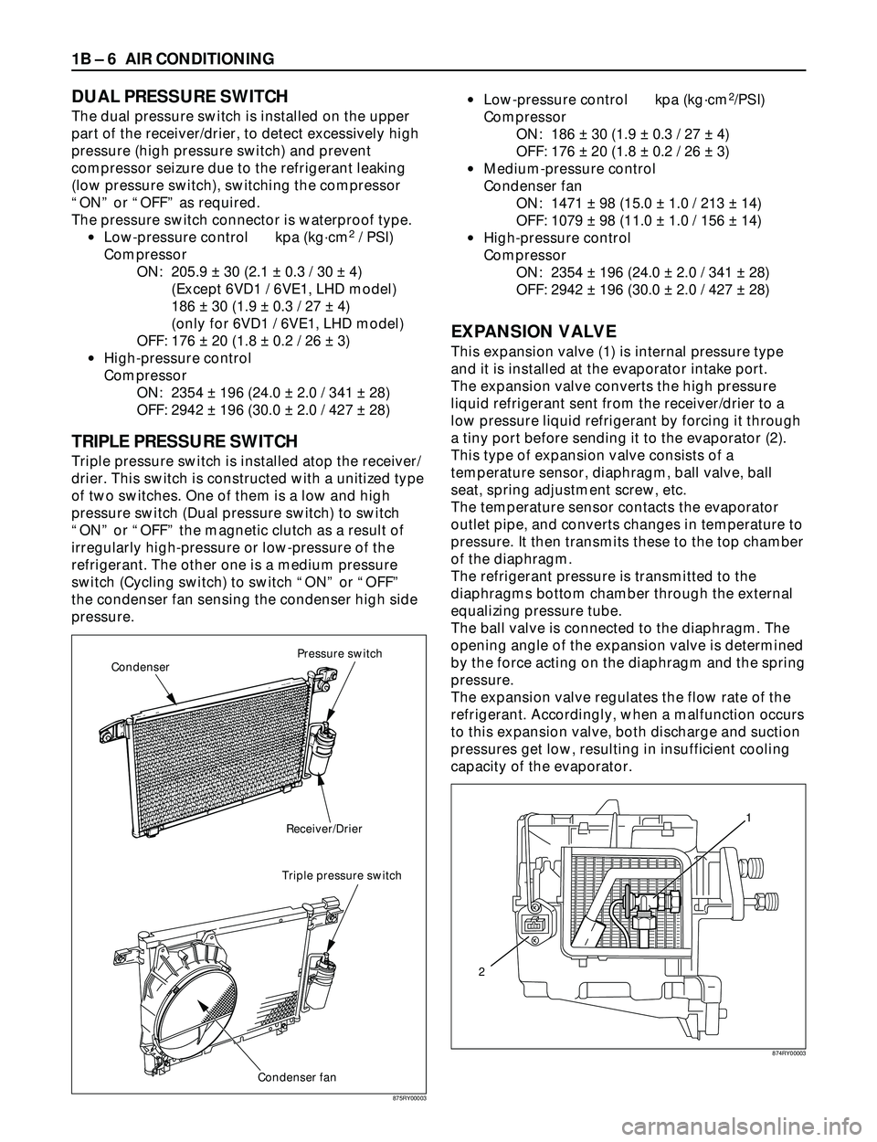
DUAL PRESSURE SWITCH
The dual pressure switch is installed on the upper
part of the receiver/drier, to detect excessively high
pressure (high pressure switch) and prevent
compressor seizure due to the refrigerant leaking
(low pressure switch), switching the compressor
ÒONÓ or ÒOFFÓ as required.
The pressure switch connector is waterproof type.
·Low-pressure control kpa (kgácm
2/ PSI)
Compressor
ON: 205.9 ± 30 (2.1 ± 0.3 / 30 ± 4)
(Except 6VD1 / 6VE1, LHD model)
186 ± 30 (1.9 ± 0.3 / 27 ± 4)
(only for 6VD1 / 6VE1, LHD model)
OFF: 176 ± 20 (1.8 ± 0.2 / 26 ± 3)
·High-pressure control
Compressor
ON: 2354 ± 196 (24.0 ± 2.0 / 341 ± 28)
OFF: 2942 ± 196 (30.0 ± 2.0 / 427 ± 28)
TRIPLE PRESSURE SWITCH
Triple pressure switch is installed atop the receiver/
drier. This switch is constructed with a unitized type
of two switches. One of them is a low and high
pressure switch (Dual pressure switch) to switch
ÒONÓ or ÒOFFÓ the magnetic clutch as a result of
irregularly high-pressure or low-pressure of the
refrigerant. The other one is a medium pressure
switch (Cycling switch) to switch ÒONÓ or ÒOFFÓ
the condenser fan sensing the condenser high side
pressure.·Low-pressure control kpa (kgácm
2/PSI)
Compressor
ON: 186 ± 30 (1.9 ± 0.3 / 27 ± 4)
OFF: 176 ± 20 (1.8 ± 0.2 / 26 ± 3)
·Medium-pressure control
Condenser fan
ON: 1471 ± 98 (15.0 ± 1.0 / 213 ± 14)
OFF: 1079 ± 98 (11.0 ± 1.0 / 156 ± 14)
·High-pressure control
Compressor
ON: 2354 ± 196 (24.0 ± 2.0 / 341 ± 28)
OFF: 2942 ± 196 (30.0 ± 2.0 / 427 ± 28)
EXPANSION VALVE
This expansion valve (1) is internal pressure type
and it is installed at the evaporator intake port.
The expansion valve converts the high pressure
liquid refrigerant sent from the receiver/drier to a
low pressure liquid refrigerant by forcing it through
a tiny port before sending it to the evaporator (2).
This type of expansion valve consists of a
temperature sensor, diaphragm, ball valve, ball
seat, spring adjustment screw, etc.
The temperature sensor contacts the evaporator
outlet pipe, and converts changes in temperature to
pressure. It then transmits these to the top chamber
of the diaphragm.
The refrigerant pressure is transmitted to the
diaphragms bottom chamber through the external
equalizing pressure tube.
The ball valve is connected to the diaphragm. The
opening angle of the expansion valve is determined
by the force acting on the diaphragm and the spring
pressure.
The expansion valve regulates the flow rate of the
refrigerant. Accordingly, when a malfunction occurs
to this expansion valve, both discharge and suction
pressures get low, resulting in insufficient cooling
capacity of the evaporator.
Pressure switch
Receiver/Drier
Triple pressure switch
Condenser fan Condenser
1
2
875RY00003874RY00003
Page 277 of 3573
COMPRESSOR OVERHAUL 1D Ð 21
Installation
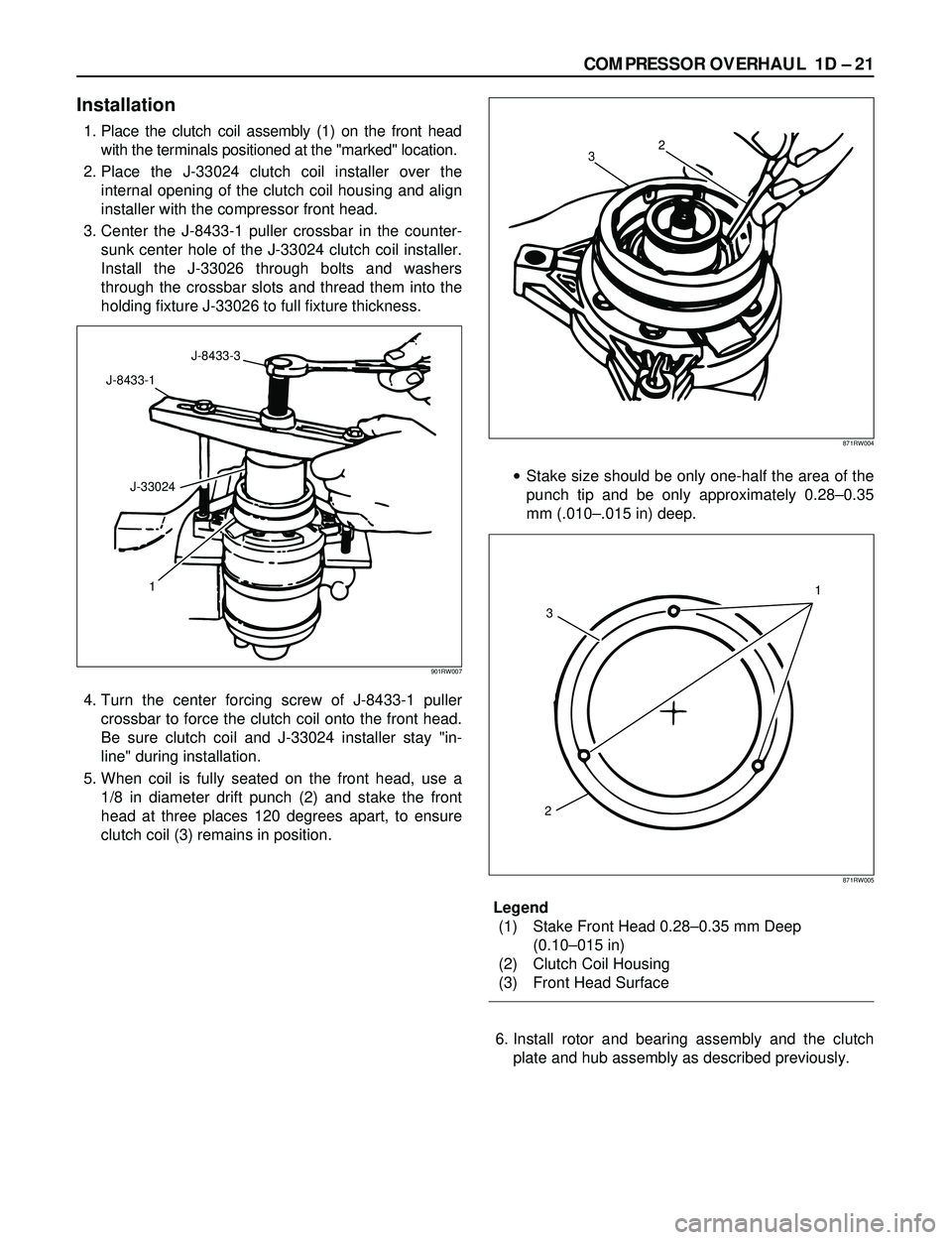
1. Place the clutch coil assembly (1) on the front head
with the terminals positioned at the "marked" location.
2. Place the J-33024 clutch coil installer over the
internal opening of the clutch coil housing and align
installer with the compressor front head.
3. Center the J-8433-1 puller crossbar in the counter-
sunk center hole of the J-33024 clutch coil installer.
Install the J-33026 through bolts and washers
through the crossbar slots and thread them into the
holding fixture J-33026 to full fixture thickness.
4. Turn the center forcing screw of J-8433-1 puller
crossbar to force the clutch coil onto the front head.
Be sure clutch coil and J-33024 installer stay "in-
line" during installation.
5. When coil is fully seated on the front head, use a
1/8 in diameter drift punch (2) and stake the front
head at three places 120 degrees apart, to ensure
clutch coil (3) remains in position.·Stake size should be only one-half the area of the
punch tip and be only approximately 0.28Ð0.35
mm (.010Ð.015 in) deep.
Legend
(1) Stake Front Head 0.28Ð0.35 mm Deep
(0.10Ð015 in)
(2) Clutch Coil Housing
(3) Front Head Surface
6. Install rotor and bearing assembly and the clutch
plate and hub assembly as described previously.
J-8433-3
J-8433-1
J-33024
1
901RW007
2
3
871RW004
1
23
871RW005
Page 279 of 3573
COMPRESSOR OVERHAUL 1D Ð 23
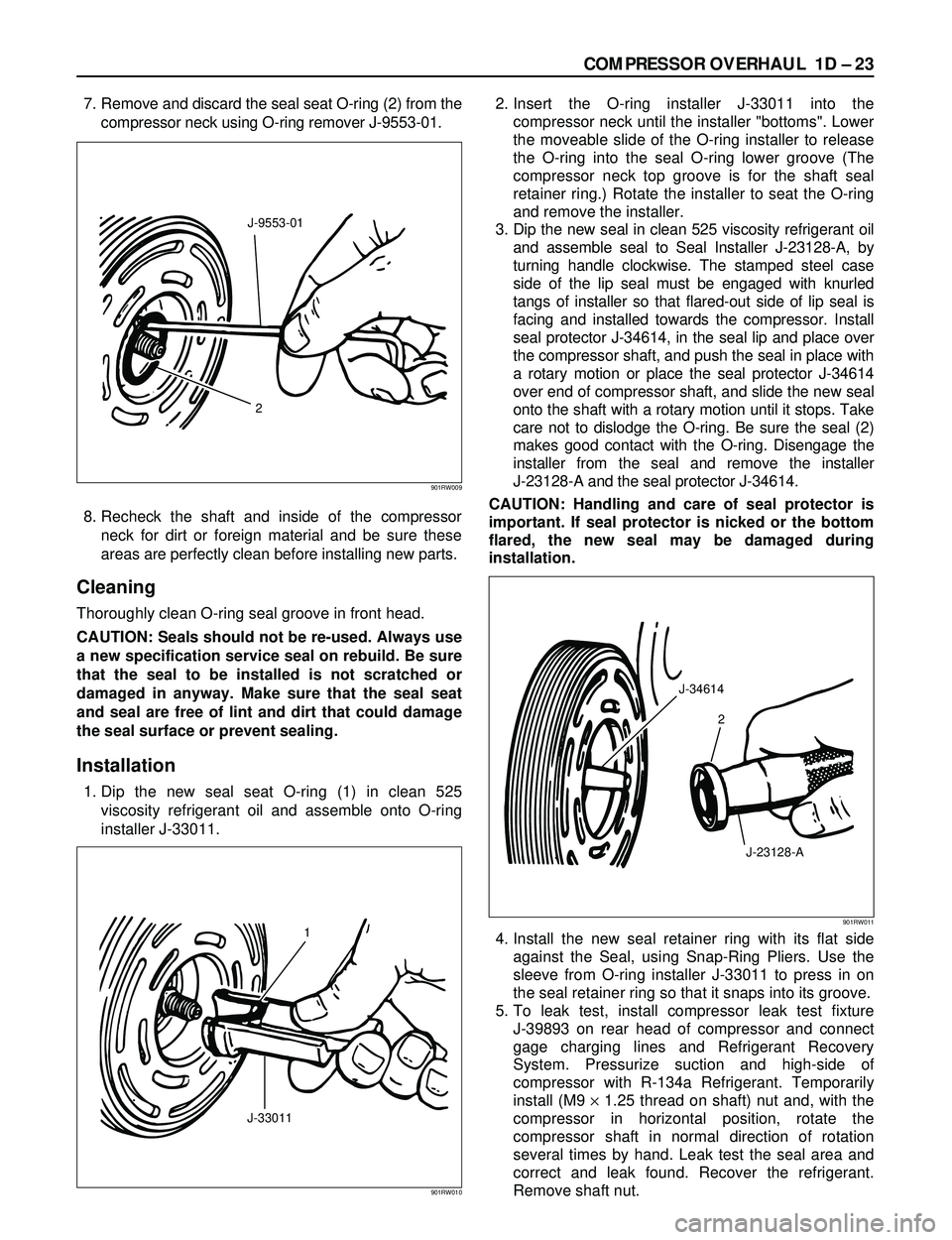
7. Remove and discard the seal seat O-ring (2) from the
compressor neck using O-ring remover J-9553-01.
8. Recheck the shaft and inside of the compressor
neck for dirt or foreign material and be sure these
areas are perfectly clean before installing new parts.
Cleaning
Thoroughly clean O-ring seal groove in front head.
CAUTION: Seals should not be re-used. Always use
a new specification service seal on rebuild. Be sure
that the seal to be installed is not scratched or
damaged in anyway. Make sure that the seal seat
and seal are free of lint and dirt that could damage
the seal surface or prevent sealing.
Installation
1. Dip the new seal seat O-ring (1) in clean 525
viscosity refrigerant oil and assemble onto O-ring
installer J-33011.2. Insert the O-ring installer J-33011 into the
compressor neck until the installer "bottoms". Lower
the moveable slide of the O-ring installer to release
the O-ring into the seal O-ring lower groove (The
compressor neck top groove is for the shaft seal
retainer ring.) Rotate the installer to seat the O-ring
and remove the installer.
3. Dip the new seal in clean 525 viscosity refrigerant oil
and assemble seal to Seal Installer J-23128-A, by
turning handle clockwise. The stamped steel case
side of the lip seal must be engaged with knurled
tangs of installer so that flared-out side of lip seal is
facing and installed towards the compressor. Install
seal protector J-34614, in the seal lip and place over
the compressor shaft, and push the seal in place with
a rotary motion or place the seal protector J-34614
over end of compressor shaft, and slide the new seal
onto the shaft with a rotary motion until it stops. Take
care not to dislodge the O-ring. Be sure the seal (2)
makes good contact with the O-ring. Disengage the
installer from the seal and remove the installer
J-23128-A and the seal protector J-34614.
CAUTION: Handling and care of seal protector is
important. If seal protector is nicked or the bottom
flared, the new seal may be damaged during
installation.
4. Install the new seal retainer ring with its flat side
against the Seal, using Snap-Ring Pliers. Use the
sleeve from O-ring installer J-33011 to press in on
the seal retainer ring so that it snaps into its groove.
5. To leak test, install compressor leak test fixture
J-39893 on rear head of compressor and connect
gage charging lines and Refrigerant Recovery
System. Pressurize suction and high-side of
compressor with R-134a Refrigerant. Temporarily
install (M9 ´1.25 thread on shaft) nut and, with the
compressor in horizontal position, rotate the
compressor shaft in normal direction of rotation
several times by hand. Leak test the seal area and
correct and leak found. Recover the refrigerant.
Remove shaft nut.
2 J-9553-01
901RW009
1
J-33011
901RW010
J-34614
2
J-23128-A
901RW011
Page 280 of 3573
1D Ð 24 COMPRESSOR OVERHAUL
6. Remove any excess oil resulting from installing the
new seal parts from the shaft and inside the
compressor neck.
7. Install the clutch plate and hub assembly as
described previously.8. Reinstall compressor belt and tighten bracket.
9. Evacuate and charge the refrigerant system.
COMPRESSOR PRESSURE RELIEF VALVE
Removal
1. Recover the refrigerant using Refrigerant Recovery
System.
2. Remove old pressure relief valve.
Installation
1. Clean valve seat area on rear head.2. Lubricate O-ring of new pressure relief valve and
O-ring assembly with new 525 viscosity refrigerant
oil. Install new valve and torque in place, 9.0 Nám
(6.1 ft lbs)
3. Evacuate and recharge the system.
4. Leak test system.
COMPRESSOR OIL
Compressor Oil Check
The oil used to lubricate the compressor is circulating
with the refrigerant.
Whenever replacing any component of the system or a
large amount of gas leakage occurs, add oil to maintain
the original amount of oil.
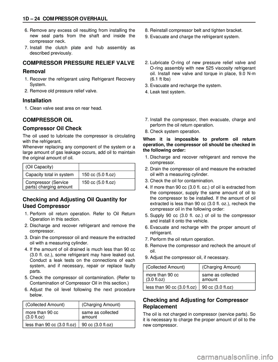
Checking and Adjusting Oil Quantity for
Used Compressor
1. Perform oil return operation. Refer to Oil Return
Operation in this section.
2. Discharge and recover refrigerant and remove the
compressor.
3. Drain the compressor oil and measure the extracted
oil with a measuring cylinder.
4. If the amount of oil drained is much less than 90 cc
(3.0 fl. oz.), some refrigerant may have leaked out.
Conduct a leak tests on the connections of each
system, and if necessary, repair or replace faulty
parts.
5. Check the compressor oil contamination. (Refer to
Contamination of Compressor Oil in this section.)
6. Adjust the oil level following the next procedure
below.7. Install the compressor, then evacuate, charge and
perform the oil return operation.
8. Check system operation.
When it is impossible to preform oil return
operation, the compressor oil should be checked in
the following order:
1. Discharge and recover refrigerant and remove the
compressor.
2. Drain the compressor oil and measure the extracted
oil with a measuring cylinder.
3. Check the oil for contamination.
4. If more than 90 cc (3.0 fl. oz.) of oil is extracted from
the compressor, supply the same amount of oil to
the compressor to be installed. If the amount of oil
extracted is less than 90 cc (3.0 fl. oz.), recheck the
compressor oil in the following order:
5. Supply 90 cc (3.0 fl. oz.) of oil to the compressor
and install it onto the vehicle.
6. Evacuate and recharge with the proper amount of
refrigerant.
7. Perform the oil return operation.
8. Remove the compressor and recheck the amount of
oil.
9. Adjust the compressor oil, if necessary.
Checking and Adjusting for Compressor
Replacement
The oil is not charged in compressor (service parts). So
it is necessary to charge the proper amount of oil to the
new compressor. (Oil Capacity)
Capacity total in system 150 cc (5.0 fl.oz)
Compressor (Service 150 cc (5.0 fl.oz)
parts) charging amount
(Collected Amount) (Charging Amount)
more than 90 cc same as collected
(3.0 fl.oz) amount
less than 90 cc (3.0 fl.oz) 90 cc (3.0 fl.oz)
(Collected Amount) (Charging Amount)
more than 90 cc same as collected
(3.0 fl.oz) amount
less than 90 cc (3.0 fl.oz) 90 cc (3.0 fl.oz)